

Briggs & Stratton 1768-0 Installation Manual
Manual de Instalaci6n y
PEG_JCTS
Briggs& Stratton Power Products Home Generator System
Installation Manual
TABLE OF CONTENTS
TABLEOF CONTENTS ......................... 2
EQUIPMENT DESCRIPTION ..................... 2
CUSTOMER RESPONSIBILITIES................... 2
INSTALLERRESPONSIBILITIES ................... 2
SAFETY RULES................................ 3
INSTALLATION PROCEDURES ................... 4
Unpacking Precautions ....................... 4
Delivery Inspection ......................... 4
Shipment Contents .......................... 4
RequiredTools/Equipment .................... 4
Home Generator System Location .............. 4
Fuel and Electrical Inlet Dimensions ............. S
Lifting the Generator ........................ 5
Access Doors .............................. 6
Automatic PowerTransfer Switch Mounting
Dimensions ......................... 7
THE GASEOUS FUELSYSTEM .................. 7-8
Fuel Consumption .......................... 9
Fuel PipeSizing ............................. 9
ESSENTIALCIRCUIT ISOLATION ................ l0
TRANSFER SWITCH .......................... I I
Generator AC Connection System ............. II
PowerWiring Interconnections ............... 12
Grounding the System ...................... 13
Control Circuit Interconnections .............. 13
Fault Detection System ...................... 13
SystemControl Panel ....................... 13
BEFOREINITIAL ENGINE START-UP.............. 14
EngineOil ................................ 14
Battery Connection ........................ 14
Fuel SupplySystem ......................... 14
INITIAL START-UP(NO LOAD) ................. 15
Electrical Checks .......................... IS
AUTOMATIC OPERATION SEQUENCE ........... 16
CheckingAutomatic Operation ............... 17
SETTING EXERCISETIMER ..................... 17
RECONFIGURING THE FUELSYSTEM ............ 18
EngineAdjustment ......................... 18
POST INSTALLATION INSPECTION .............. 19
REFERENCES ................................ 19
Standards Index ........................... 19
FuelComparison Chart ..................... 20
Sizeof Propane Tank Required atVarious Temperatures
When Kept at Least Half Full .......... 20
INSTALLATION NOTES......................... 21
EQUIPMENT
DESCRIPTION
This system consists of an engine driven AC generator
designedto provide backup electrical power for operating
compatible electrical loads through the supplied automatic
power transfer switch.
This manualcontains installation, startup and adjustment
instructions for Home Generator Systemsthat operates
120and/or 240Volt.singlephase,60Hz devices.The
generator may be operated on LP or natural gasfueI.A
separate owner's manual (part number 191187) contains
specifications,operating and maintenance instructions for
these models.
Everyeffort hasbeen expended to makesure that the
informationinthis manual is both accurate and current
However, the manufacturer reserves the right to change,
alter or otherwise improvethe systemat any time without
prior notice.
_ CAUTION! Do Not tamper with engine
governed speed.High operating speedsare
dangerous and increasethe risk of personal injury
or damageto equipmen_
CUSTOMER
RESPONSIBILITIES
• Read and follow the instructions given in the Owner's
Manual, especially the section regarding selecting essential
circuits.
• Follow a regular schedule in maintaining, caring for and
using your Home Generator System, as specified in the
Owner's Manual.
INSTALLER
RESPONSIBILITIES
• Read and observe the safety rules.
• Read and follow the instructions given in this Installation
and Start-up Manual.
• Employ good workmanship techniques to ensure a long
lasting and trouble-free backup power installation.
w
2
Bri_s & Stratton Power Products Home Generator System
Installation Manual
ComokbyEmo*_JC_,_
SAFETY RULES
The safety alert symbol (_,) is used with a signalword
(DANGER, CAUTION,WARNING), a pictorial and/or a
safety messageto alert you to hazards.DANGER indicates
a hazardwhich, if not avoided,will result in death or serious
injury. WARNING indicates a hazard which, if not avoided,
couldresult in death or serious injury. CAUTION
indicatesa hazardwhich, if not avoided,might result in
minor or moderate injury. CAUTION, when used
without the alert symbol, indicates a situation that could
result in equipment damage.Follow safety messagesto
avoid or reduce the risk of injury or death.
WARNING
Do not handlegenerator or electrical cordswhile standing in
water, while barefoot, or while hands or feet are wet,
If you mustwork around a unit while it is operating, stand on
an insulateddry surface to reduce shock hazard.
Do not allow unqualified persons or children to operate or
service generator.
In caseof an accident caused by electrical shock, immediately
shut down the source of electrical power. If this is not
possible,attempt to free the victimfrom the live conductor.
Avoid direct contact with the victim, Use a non-
conducting implement, such as a rope or board, to free the
victim from the live conductor. If the victim is unconscious,
apply first aid and get immediate medical help.
Before performing any maintenance on the generator,
disconnect the battery cable indicatedby a NEGATIVE,
NEG or (-) first-When finished, reconnect that cable last.
After your Home Generator System is installed,the generator
maycrank and start without warning anytime there is a
power failure.To prevent possible injury, always set the
AUTO/OFF/MANUAL switch to OFF AND remove the
I5Amp fuse BEFORE working on the equipment.
WARNING
Only c)ualified electricians and gaseous fuel
technicians should attempt installation of this
system, which must strictly comply with applicable
codes, standards and regulations.
WARNING
NOT INTENDED FOR USEAS PRIMARY
POWER IN PLACE OF UTILITY OR IN
LIFE-SUPPORT APPLICATIONS
WARNING
Install the fuel supply system accordingto applicablefuel-gas
codes.
Before placing the Home Generator System intoservice, the
fuel system lines must be properly purged and leak tested.
After the system is installed,you should inspect the fuel
system periodically.
No leakage is permitted.
CAUTION
Adequate, unobstructed flow of cooling and ventilating air is
critical to correct generator operation.
Keep at least 2 feet of clearance on all sides of generator for
adequate ventilation.
Despite the safe design of the Home Generator System,
operating this equipment imprudently, neglecting its
maintenance or being careless can cause possible injury or
death.
Remain alert at all times while working on this equipment.
Never work on the equipment when you are physicallyor
mentally fatigued,
Do not use the generator or any of its parts asa step.
Steppingon the unit cancausestress and break parts,This
may result in dangerous operatingconditionsfrom leaking
exhaust gases,fuel leakage,oil leakage,and soforth.
3

Bri?a_s& Stratten Power Products Home Generator System
Installation Manual
INSTALLATION
PROCEDURES
Unpacking Precautions
The unit is shipped bolted to its mounting pad, ready for
hookup. Use care to avoid damagefrom dropping, bumping,
collision, etc. Store and unpack carton with the proper side
up,asnoted on the shipping carton.
Delivery Inspection
After removing the carton, carefullyinspectthe Home
Generator andAutomatic PowerTransfer Switch
components for any damagethat may haveoccurred during
shipment.
IMPORTANT: If loss or damageis noted at time of
delivery,havethe person(s) making delivery note all damage
on the freight bill and affix his signature under the
consignor's memo of lossor damage.If loss or damage is
noted after delivery, separate the damagedmaterials and
contact the carrier for claim procedures. Missingor
damagedparts are not warranted.
Shipment Contents
The Home Generator System is supplied with:
BackupPower generator
Pre-attached mounting pad
Automatic PowerTransfer switch
One 24" flexible hook-up pipe
Installation and start-up manual (P/N 191186)
Owner's manual(P/N 191187)
Product warranty sheet (P/N 190881)
Installation checklist (P/N 190840)
Three accessdoor keys
Four lifting hole plugs
Oil fill spout
Touch-up paint
One spare 15A fuse
Diagnostic LED kit (diode/plate/decal/pin connectors (2))
Required Tools/Equipment
• Two 48" lengths of I" OD pipe (NOT conduit)
• Hole punches for 16ga steer
• Torque screwdriver, 5 to 50 inch-pound range
Home Generator System Location
TO THE INSTALLER: Consult with the owners
and convey any technical considerations that might
affect their wishes, before applying these general
guidelines.
Generator Clearances
The generator enclosure mustbe a minimum of 3 f_
(92 cm) from combustible material (NFPA 37). Leaveat
least3 ft. (92 cm) all around the enclosure for accessto the
inside of the enclosure (NEC Art. II 0-26a,Art. 110-26b).
The unit's exhaust port must be at least S ft. (152 cm) from
any building opening (window, door, vent etc.), and the
exhaustmust not be able to accumulate in any occupied
area (Figure I).
Exhaust
Exhaustport must be
5 ft (152 cm) minimum
distancefrom building
openings
General Location Guidelines
• Install the unit outdoors ONLY. NO MODIFICATIONS
WILLALLOW INSIDE INSTALLATION!
Place the unit in a prepared location that is fiat and has
provisions for water drainage.
• Instalt the unit where air inlet and outlet openings will
not become obstructed by leaves, grass, snow, etc. If
prevailing winds will cause blowing or drifting, you may
need to construct a windbreak to protect the unit.
• In locations where strong winds blow from one
direction, face the generator air inlet openings into the
prevailing winds, if possible.
/
4
Bri_s & Stra_on Power ProductsHome Generator System
Installation Manual
• Installthe generator as closeaspossibleto the
Automatic PowerTransfer Systemto reduce the length
of wiring and conduit
• Install the generator as close aspossible to the fuel
supply to reducelength of pipes.
_k CAUTION! Lawsor local codes mayregulatethe
distance to the fuel supply.
The Home Generator Systemis shippedalreadyattached
to its mounting pad.Unlessmandatedby localcode,no
concreteslabis required.
If mandatedbylocalcode, detachthe unitfrom itssupplied
base.Construct a concrete slabat least 3 inchesthick and
6 incheslonger and wider than the unit_Attachunit to slab
with I/4" diameter (minimum) masonry anchor bolts long
enough to retain the unit Use the mounting padholes as
anchor bolt Iocators.
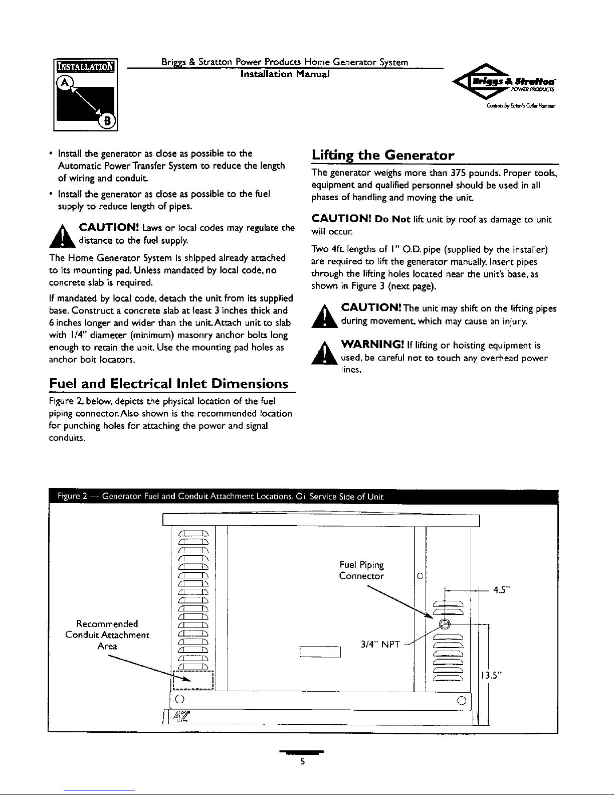
Fuel and Electrical Inlet Dimensions
Figure2, below, depicts the physicallocation of the fuel
piping connector.Also shown is the recommended location
for punching holesfor attaching the power and signal
conduits.
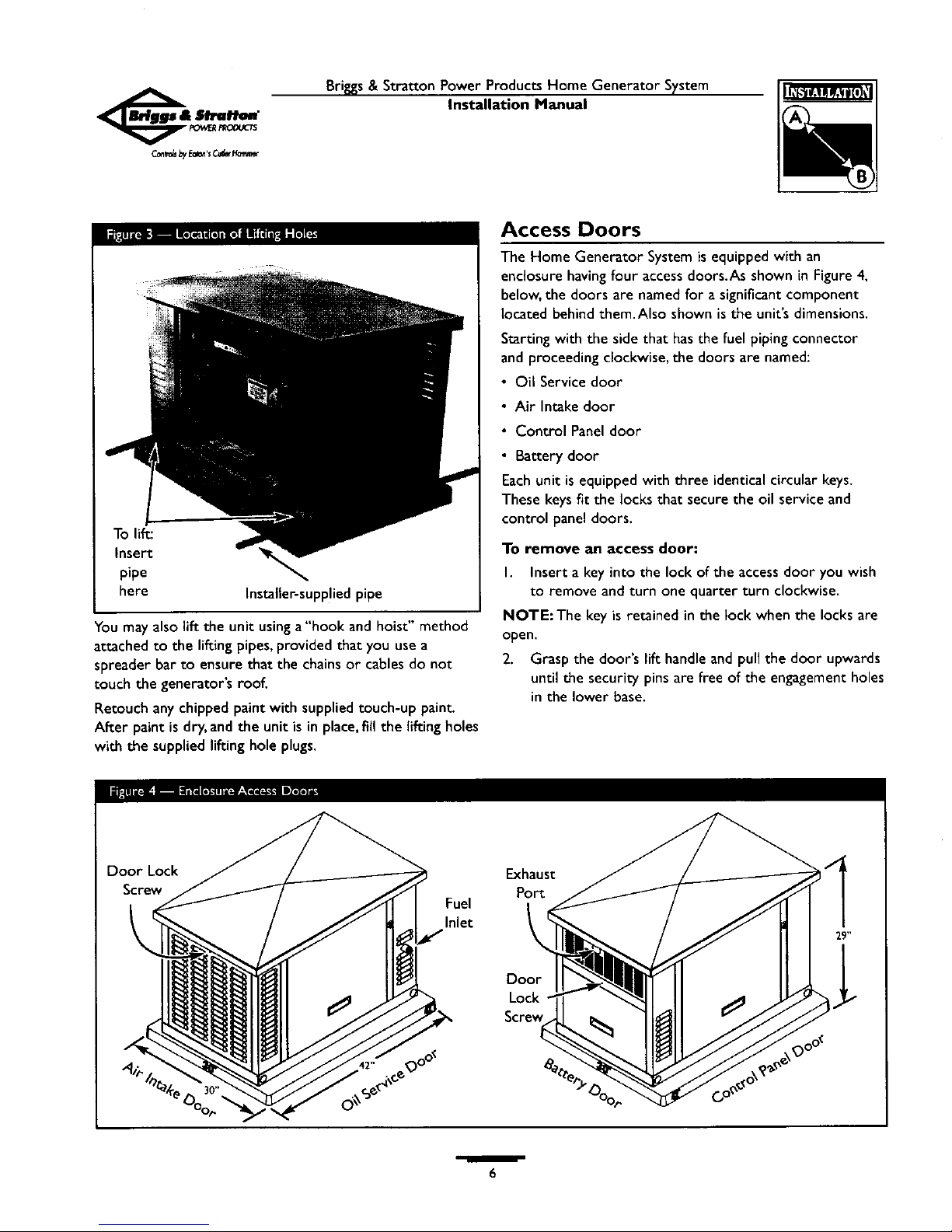
Lifting the Generator
The generator weighsmore than 375 pounds. Proper tools,
equipment and qualified personnel should be used in all
phasesof handlingand moving the unit
CAUTION! Do Not lift unit by roof as damage to unit
will occur.
Two 4E. lengths of I" O.D. pipe (supplied by the installer)
are required to lift the generator manually.Insert pipes
through the lifting holes located near the unit's base,as
shown in Figure 3 (next page).
_ CAUTIONiThe unit may shifton the lifting pipes
during movement, whichmay cause an injury.
_ WARNING! If lifting or hoisting equipment is
used, be careful not to touch any overhead power
lines.
Recommended
Conduit Attachment
Area
I
K_22_
_22222h
lI2222125
(2)
o
3/4" NPT _ I _
©
I
-- 4.5"
13.5"
5
Bri_s&StrattonPowerProductsHomeGeneratorSystem
Installation Manual
To lift:
Insert
pipe
here
Installer-supplied pipe
You may also lift the unit usinga"hook andhoist" method
attached to the lifting pipes,provided that you use a
spreader bar to ensure that the chainsor cables do not
touch the generator's roof.
Retouch any chipped paint with supplied touch-up paint.
After paint is dry, and the unit is in place,fill the lifting holes
with the supplied lifting hole plugs.
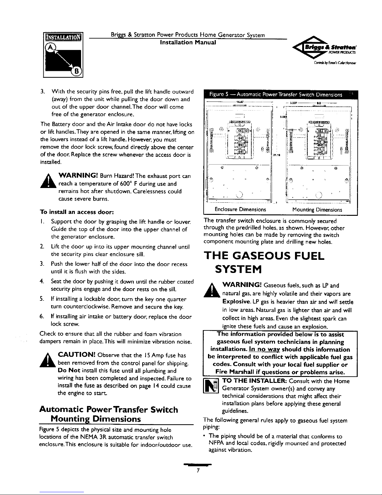
Access Doors
The Home Generator System is equipped with an
enclosure having four access doors.As shown in Figure 4,
below, the doors are named for a significant component
located behind them.Also shown is the unit's dimensions.
Starting with the side that has the fuel piping connector
and proceeding clockwise, the doors are named:
• Oil Service door
• Air Intake door
• Control Panel door
• Battery door
Each unit is equipped with three identical circular keys.
These keys fit the locks that secure the oil service and
control panel doors.
To remove an access door:
I. Insert a key into the lock of the access door you wish
to remove and turn one quarter turn clockwise.
NOTE:The key is retained in the lock when the locks are
open.
2. Grasp the door's lift handle and pull the door upwards
until the security pins are free of the engagement holes
in the lower base.
Door Lock
Screw
Fuel
Inlet
Exhaust
Port
2911
ooo'
Door
Lock
Screw
0oO_
w
6
Briggs& Stratton Power Products Home Generator System
Installation Manual
3. With the security pins free, pull the lift handle outward
(away)from the unit while pulling the door down and
out of the upper door channel.The door will come
free of the generator enclosure.
The Battery door andtheAir Intake door do not havelocks
or lift handles.Theyare opened in the samemanner,lifting on
the louvers instead of a lift handle.However,you must
remove the door lock screw,found directly abovethe center
of the door. Replacethe screw whenever the accessdoor is
installed.
_ WARNING! Burn Hazard!The exhaust port can
reach a temperature of 600° Fduring useand
remains hot after shutdown. Carelessnesscould
causesevere burns.
To install an access door:
I. Support the door by grasping the lift handle or louver.
Guide the top of the door into the upper channel of
the generator enclosure.
2. Lift the door up into its upper mounting channel until
the security pins clear enclosure sill.
3. Push the lower half of the door into the door recess
until it is flush with the sides.
4. Seat the door by pushing it down until the rubber coated
security pins engage and the door rests on the sill.
5. If installing a Iockable door, turn the key one quarter
turn counterclockwise. Remove and secure the key.
6. If installing air intake or battery door, replace the door
lock screw.
Check to ensure that all the rubber and foam vibration
dampers remain in place.This will minimize vibration noise.
_, CAUTION! Observe that the 15Amp fuse has
been removed from the control panel for shipping.
Do Not install this fuse until all plumbing and
wiring has been completed and inspected. Failure to
install the fuse as described on page 14could cause
the engine to start
Automatic PowerTransfer Switch
Mounting Dimensions
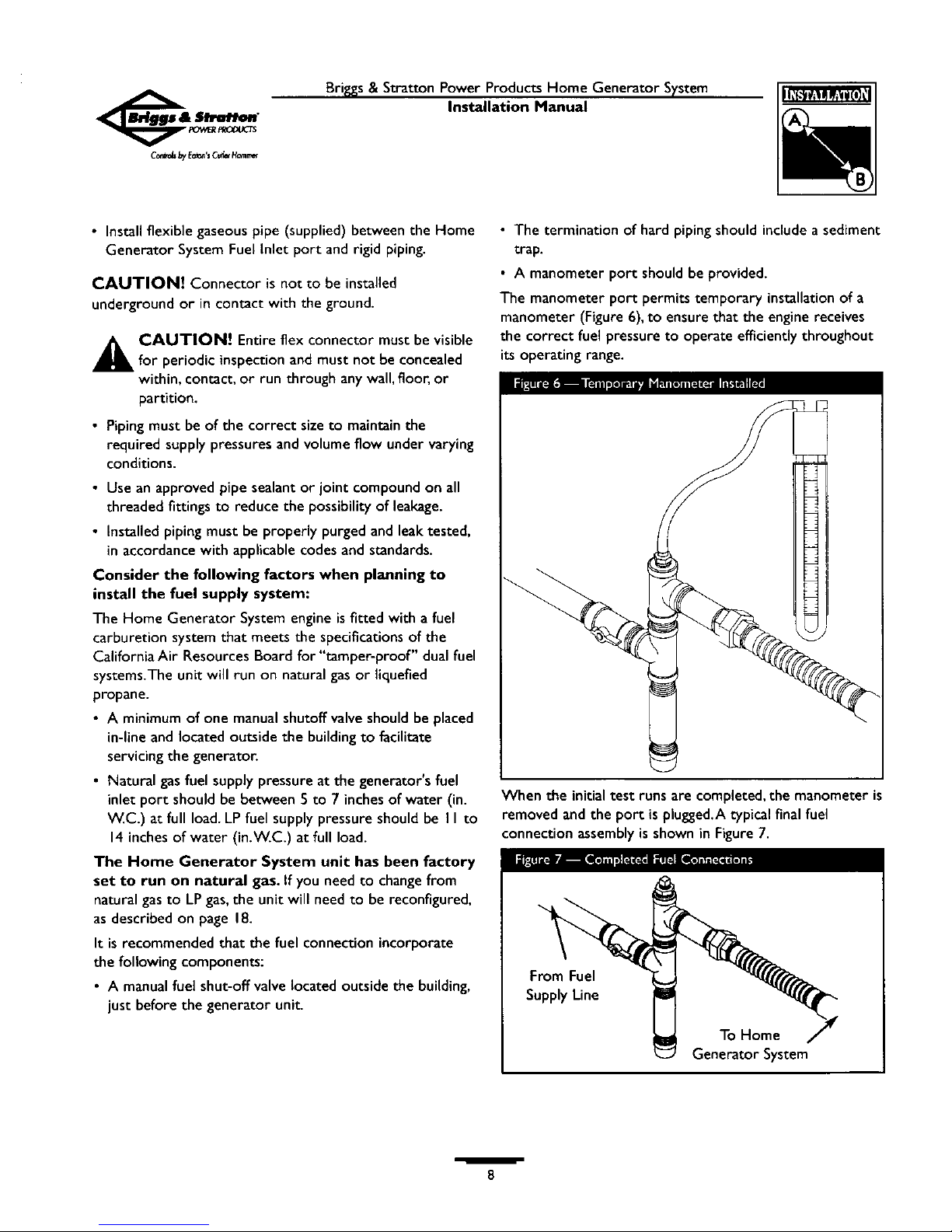
Figure 5 depicts the physical size and mounting hole
locations of the NEMA 3R automatic transfer switch
enclosure.This enclosure is suitable for indoor/outdoor use.
Enclosure Dimensions Mounting Dimensions
The transfer switch enclosure is commonly secured
through the predrilled holes, as shown. However, other
mounting holes can be made by removing the switch
component mounting plate and drilling new holes.
THE GASEOUS FUEL
SYSTEM
_, WARNING! Gaseous fuels, such asLP and
natural gas,are highlyvolatileand their vaporsare
Explosive. LPgasis heavier than air andwill settle
in low areas.Natural gas islighter than air and will
collect in high areas.Even the slightest spark can
ignite these fuels and causean explosion.
The information provided below isto assist
gaseous fuel system technicians in planning
installations. In no wav should this information
be interpreted to conflict with applicable fuel gas
codes. Consult with your local fuel supplier or
Fire Marshall if questions or problems arise.
TO THE INSTALLER: Consult with the Home
Generator Systemowner(s) and conveyany
technical considerations that might affect their
installationplansbefore applying these general
guidelines.
The following general rules apply to gaseousfuel system
piping:
• The piping should be of a material that conforms to
NFPA and local codes,rigidly mounted and protected
against vibration.
7
Bri_._s& Stratton Power Products Home Generator System
Installation Manual
• Install flexible gaseous pipe (supplied) between the Home
Generator System Fuel Inlet port and rigid piping.
CAUTION! Connector is not to be installed
underground or in contact with the ground.
_k CAUTION! Entire flex connector must be visible
for periodic inspection and must not be concealed
within, contact, or run through any wall, floor, or
partition.
• Piping must be of the correct size to maintain the
required supply pressures and volume flow under varying
conditions.
• Use an approved pipe sealant or joint compound on all
threaded fittings to reduce the possibility of leakage.
• Installed piping must be properly purged and leak tested,
in accordance with applicable codes and standards.
Consider the following factors when planning to
install the fuel supply system:
The Home Generator System engine is fitted with a fuel
carburetion system that meets the specifications of the
California Air Resources Board for "tamper-proof" dual fuel
systems.The unit will run on natural gas or liquefied
propane.
• A minimum of one manual shutoff valve should be placed
in-line and located outside the building to facilitate
servicing the generator.
• Natural gas fuel supply pressure at the generator's fuel
inlet port should be between 5 to 7 inches of water (in.
W.C.) at full load. LP fuel supply pressure should be I I to
14 inches of water (in.W.C.) at full load.
The Home Generator System unit has been factory
set to run on natural gas. If you need to change from
natural gas to LP gas, the unit will need to be reconfigured,
as described on page 18.
It is recommended that the fuel connection incorporate
the following components:
• A manual fuel shut-off valve located outside the building,
just before the generator unit.
• The termination of hard piping should include a sediment
trap.
• A manometer port should be provided.
The manometer port permits temporary installation of a
manometer (Figure 6),to ensure that the engine receives
the correct fuel pressure to operate efficiently throughout
its operating range.
When the initial test runs are completed, the manometer is
removed and the port is plugged.A typical final fuel
connection assembly is shown in Figure 7.
From Fuel
Supply Line
To Home
Generator System
W
8
Brings & Stratton Power Products Home Generator System
Installation Manual
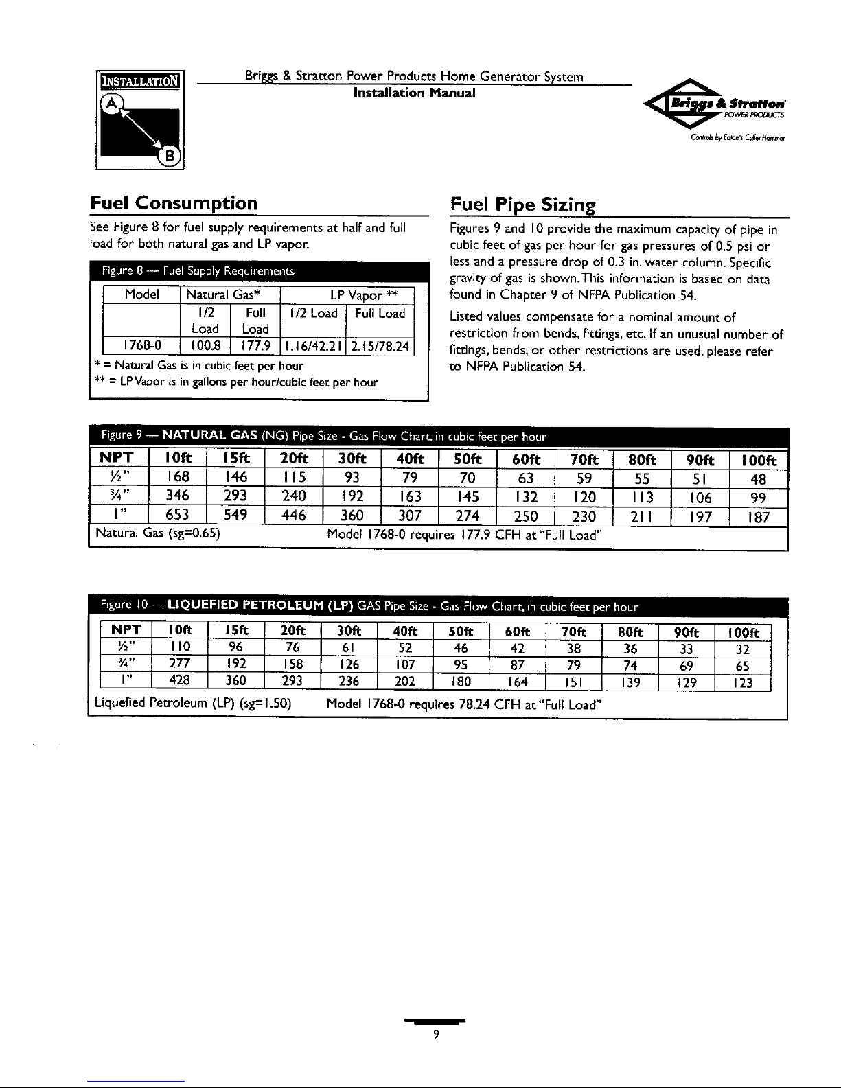
Fuel Consumption
See Figure 8 for fuel supply requirements at half and full
load for both natural gasand LPvapor.
Model Natural Gas* LPVapor *_
I/2 Full I/2 Load Full Load
Load Load
1768-0 100.8 177.9 1.16/42.21 2.15/78.24
* = NaturalGasisincubicfeetper hour
** = LPVaporisin gallonsperhour/cubicfeet per hour
Fuel Pipe Sizing
Figures 9 and 10 provide the maximum capacity of pipe in
cubic feet of gas per hour for gas pressures of 0.5 psi or
less and a pressure drop of 0.3 in. water column. Specific
gravity of gas is shown.This information is based on data
found in Chapter 9 of NFPA Publication 54.
Listed values compensatefor a nominal amount of
restriction from bends,fittings, etc. If an unusual number of
fittings, bends,or other restrictions are used,pleaserefer
to NFPA Publication 54.
10_ 20_
½" 168 146 115
¾" 346 293 240
I" 653 549 446
Natural Gas(sg=0.65)
70_
93 79 70 63 59
192 163 145 132 120
360 307 274 250 230
Model1768-0requires177.9 CFH at"FullLoad"
90_
55 51 48
113 106 99
211 197 187
NPT 10_ 15_ 20_ 30_ 40_ 50_ 60_ 70_ 80_ 90fi 100_
½" II0 96 76 61 52 46 42 38 36 33 32
¾" 277 192 158 126 107 95 87 79 74 69 65
I" 428 360 293 236 202 180 164 151 139 129 123
Liquefied Petroleum (LP) (sg=l.50)
Model 1768-0 requires 78.24 CFH at"Full Load"
/
9
Briggs& Stratton Power Products Home Generator System
Installation Manual
ESSENTIAL CIRCUIT
ISOLATION
Essentialelectrical loads are loadsthat will be powered by
the Home Generator System.Essentialloads are grouped
together and wired into the transfer switch.
_k AUTION! This Home Generator SystemMUSTbe installedasdescribed herein.
TO THE INSTALLER: Consult with Home
Generator System owner(s) to discuss their
"Selection of Essential Circuits", described in the
owner's manual.
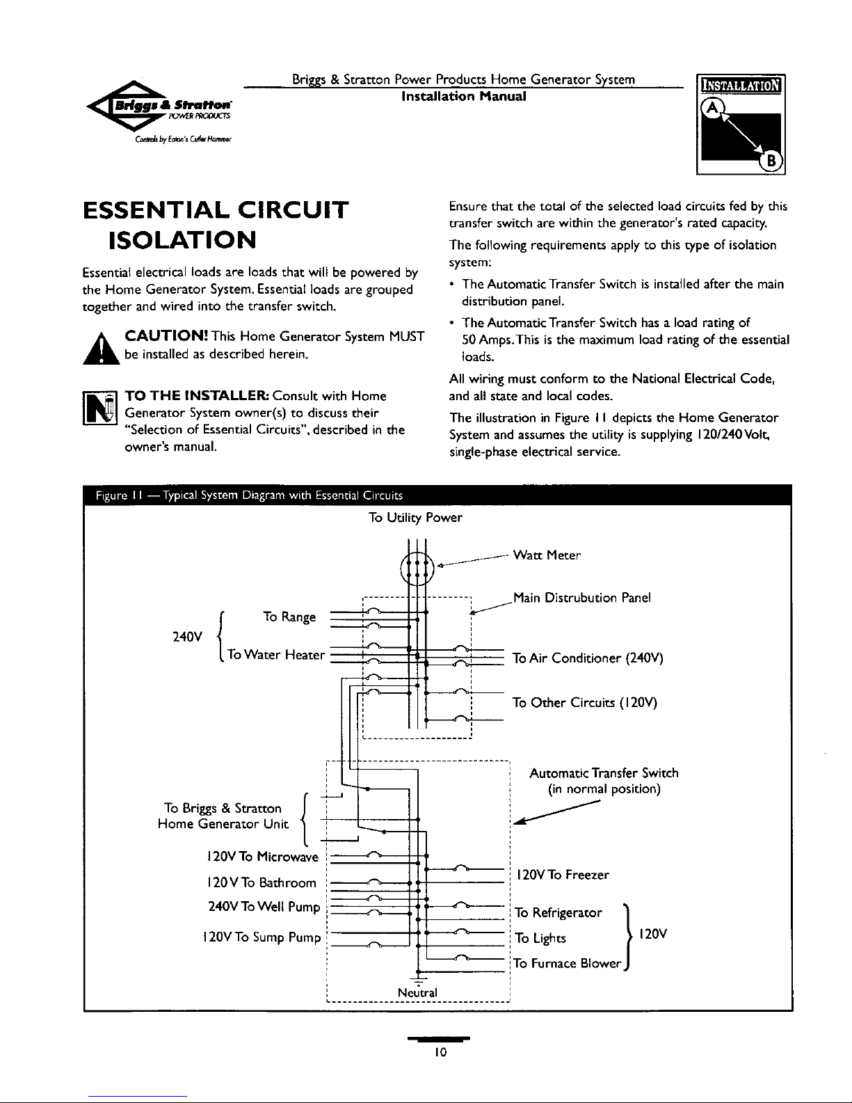
Ensure that the total of the selected load circuits fed by this
transfer switch are within the generator's rated capacity.
The following requirements apply to this type of isolation
system:
• The AutomaticTransfer Switch is installed after the main
distribution panel.
• The AutomaticTransfer Switch has a load rating of
50 Amps.This is the maximum load rating of the essential
loads.
All wiringmust conformto the National ElectricalCode,
and all state and local codes.
The illustration in Figure I I depicts the Home Generator
System and assumesthe utility is supplying 120/240Volt,
single-phaseelectrical service.
To Utility Power
240V I To Range
LToWater Heater
To Briggs & Stratton ',
Home Generator Unit i
J
120V To Microwave !
120VTo Bathroom ',----_-_
Watt Meter
.......; Main Distrubution Panel
i
ToAir Conditioner (240V)
To Other Circuits (120V)
I Automatic Transfer Switch
I (in normal position)
_' 120VToFreezer
240VTo Well Pump :_ _ i!To Refrigerator 1
120VTo Sump Pump _______ -- llTo Lights ?
'To Furnace BlowerJ
Neutral
120V
/
10
Briggs& Stratton Power Products Home Generator System
Installation Manual
TRANSFER SWITCH
The AutomaticTransfer Switch supplied with the Home
Generator System is enclosed in a NEMAType 3R
enclosure suitable for indoor/outdoor use.Guidelines for
mounting the Automatic Transfer Switch include:
• The switch must be installed with minimum NEMA 3R
hardware for conduit connections.
• Install the switch on a firm, sturdy supporting structure.
• To prevent switch contact distortion, level the switch if
necessary.Thiscan be done by placingwashers between
the switch enclosure and the mounting surface.
• Never install the switch where anycorrosive substance
might drip onto the enclosure.
• Protect the switch at all times againstexcessive moisture,
dust,dirt, lint, construction grit and corrosive vapors.
The typical internal-mount Automatic Power Transfer
Switch is depicted in Figure 12.It is best if it is mounted
near the main distribution panel,either insideor outside.
Discusslayout suggestions/changeswith the owner before
beginningthe system installation process.
Main
Distribution
Panel
Automatic
Generator AC Connection System
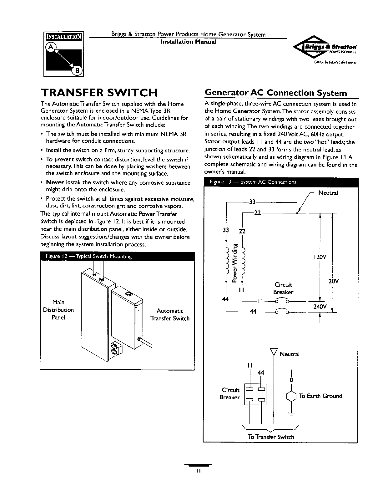
A single-phase,three-wire AC connection system is usedin
the Home Generator System.The stator assemblyconsists
of a pair of stationary windings with two leadsbrought out
of each winding.The two windings are connected together
in series,resulting in a fixed 240Volt AC, 60Hz outpu_
Stator output leads I I and 44 are the two "hot" leads;the
junction of leads 22 and 33 forms the neutral lead,as
shown schematically and aswiring diagram in Figure 13.A
complete schematic and wiringdiagram can be found in the
owner'smanual.
33
33 22
o.
Circuit
I I Breaker
1--II ---o+++T"o--
I L o+
Neutral
T
120V
II
44
Circuit I _
Breaker
7 Neutral
I
0
To Earth Ground
ToTransferSwitch
/
II
Briggs& StrattonPower Products Home Generator System
Installation Manual
Power Wiring Interconnections
All wiring must be the proper size, properly supported, of
approved insulative qualities,and protected by NEC
approved conduit Use flexible conduit between the
enclosure and any rigid conduit
_ AUTION! Per NEC code, power voltage leads
must be run in separate conduit from Low voltage
transfer switch "signal" leads.
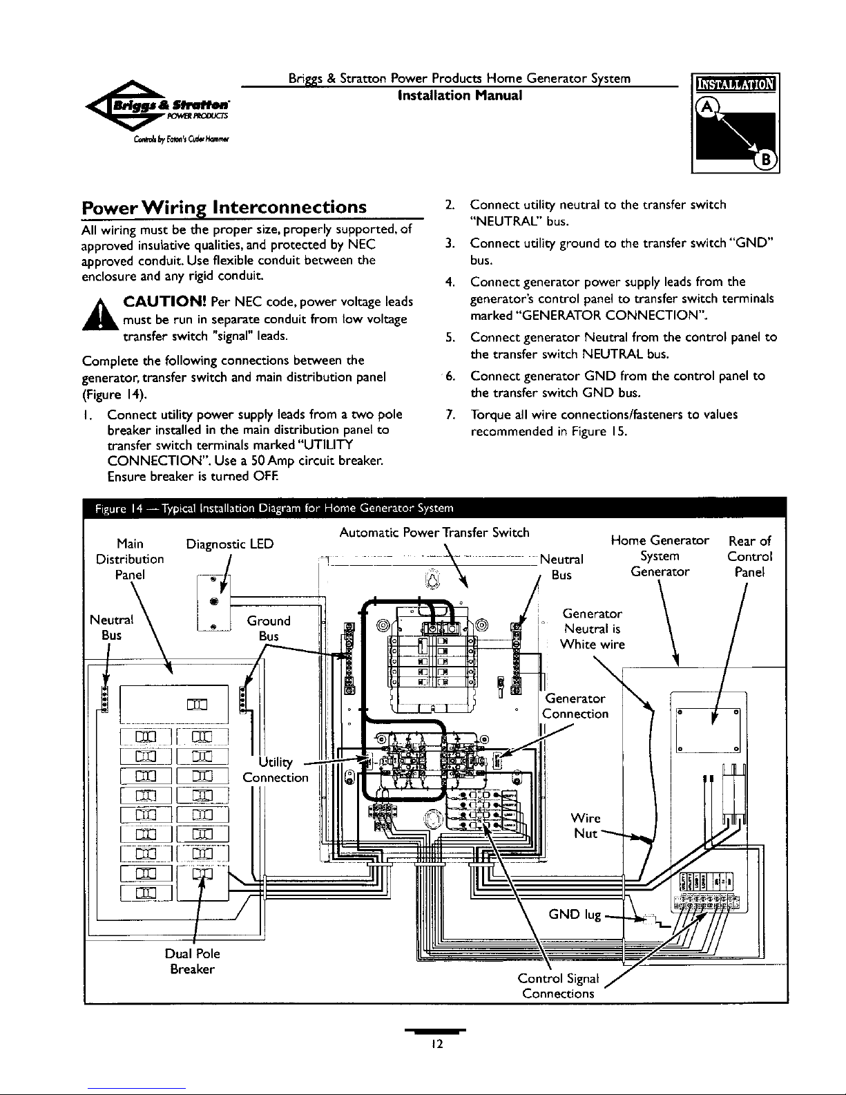
Complete the following connections between the
generator, transfer switch and maindistribution panel
(Figure 14).
I. Connect utility power supply leadsfrom a two pole
breaker installed in the main distribution panel to
transfer switch terminals marked "UTILITY
CONNECTION". Use a 50Amp circuit breaker.
Ensurebreaker is turned OFE
2. Connect utility neutral to the transfer switch
"NEUTRAL" bus.
3. Connect utility ground to the transfer switch"GND"
bus.
4. Connect generator power supply leads from the
generator's control panel to transfer switch terminals
marked "GENERATOR CONNECTION".
5.
6.
7.
Connect generator Neutral from the control panel to
the transfer switch NEUTRAL bus.
Connect generator GND from the control panel to
the transfer switch GND bus.
Torque all wire connections/fasteners to values
recommended in Figure 15.
Main Diagnostic LED
Distribution /
Panel r-_]
Bus
I
Dual Pole
Breaker
Ground
P,us
Utility
Connection
Automatic Power Transfer Switch
"i_j _ NeutralBus
Home Generator Rear of
System Control
Generator Panel
Generator
Neutral is
White wire
Control Signal
Connections
/
12
Briggs&Stratton Power Products Home Generator System
Installation Manual
Grounding the System
Installer-supplied minimum 10AWG strandedcopperwire
isconnected to the generator housingGND lug and routed
through conduit to the Automatic Transfer Switch's GND
bus.Continue the 10AWG wire through conduit to the
main distribution panel ground bus.Torque all wire
connections/fasteners to values recommended in Figure 15.
Generator grounding rod is used ONLY if required
by local code.
_-_llk'] "- • ..-.,-. • .L_&vBIM_
CONNECTIONS:
In Main Distribution Panel:
Refer to panel manufacturerspecs
In Transfer Switch:
UTILITY CONNECTION lugs
GENERATOR CONNECTION lugs
GND Bar and NEUTRAL Bar:
14-10AWG
8AWG
6-4 AWG
Circuit Breakers:
Refer to circuit breaker
manufacturer specs
Control Circuit Interconnections
Control circuit interconnections consist of "Utility" and
"Load" leads, plus leads"15","205", and "206".These seven
signal leads must be routed in conduit that is separate from
the AC power leads. Control lead functions are briefly
described as follows:
• "Utility I" and "Utility 2" deliver utility power to the
generator's circuit board.
• "Load I" and "Load 2" are used to operate the exercise
timer on the generator's circuit board.
• Leads "15","205", and "206" supply control signals to the
Automatic Transfer Switch.
Using installer-supplied minimum 14AWG stranded copper
wire, connect each control circuit terminal in the generator
to its corresponding terminal in the Automatic Transfer
Switch.Torque all wire connections/fasteners to values
recommended in Figure 15.
Torque Value
Minimum Maximum
35 in-rb 45 in-lb
35 in-lb 45 in-lb
20 in-lb
25 in-lb
35 in-lb
Fault Detection System
The righton the control panel is referred to as the
Diagnostic LED. It wilt turn on and off in a series of blinks if
certain problems are detected in the HGS.An extra LED
and mounting plate is supplied so that it can be installed at a
convenient insidelocation.The owner will use it to observe
the status of the HGS.
To install the remote LED panel:
• Apply the supplied decal.
• Pullthe LED through the mountingplatefrom the back
until it snapsin place.
• Usingminimum 18AWG wire, connect the remote LED
to the generator control panel using supplied pin
connectors. Use wire nuts to attach wire to LED leads.
• Attach mounting plate to installer-supplied low voltage
electrical box.
Refer to the section "Fault Detection System" in the
Owner's Manualfor operation.
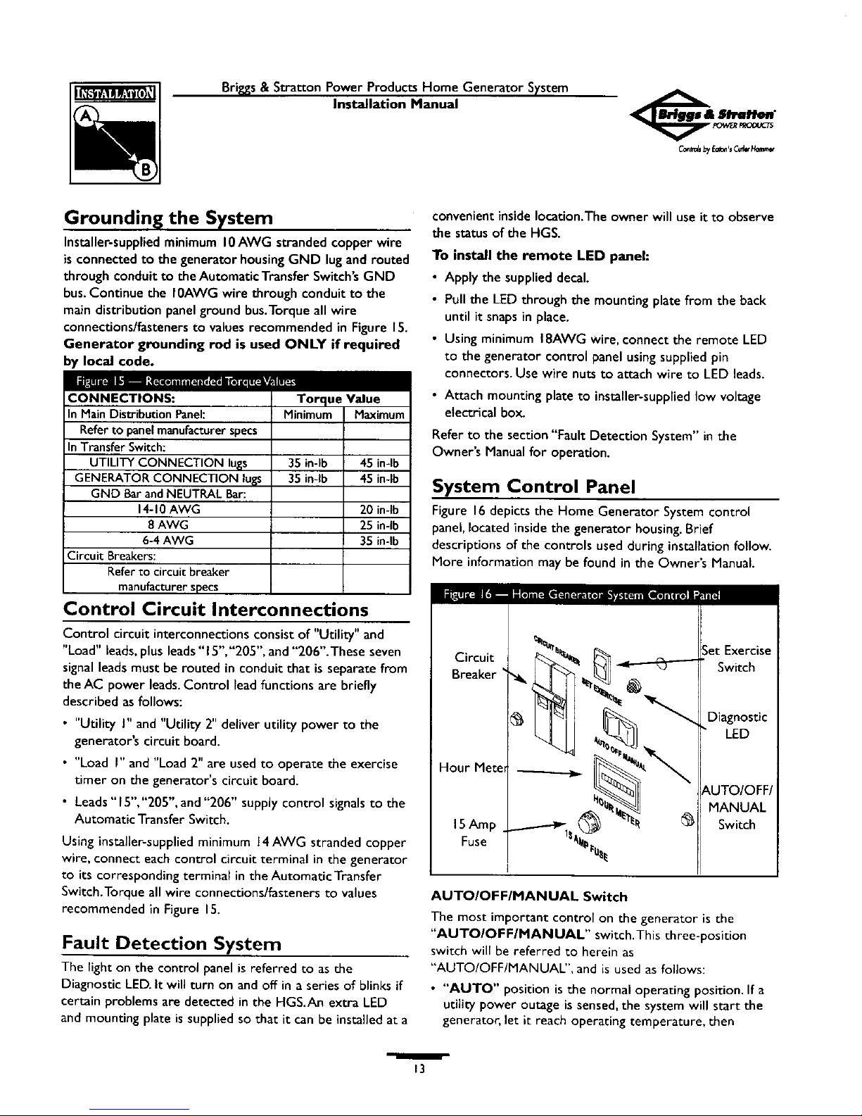
System Control Panel
Figure 16 depicts the Home Generator System control
panel, located inside the generator housing. Brief
descriptions of the controls used during installation follow.
More information may be found in the Owner's Manual
Circuit
Breaker
Hour Met_
15Amp
Fuse
;et Exercise
Switch
Diagnostic
LED
MANUAL
Switch
AUTO/OFF/MANUAL Switch
The most important control on the generator is the
"AUTO/OFF/MANUAL" switch.This three-position
switch will be referred to herein as
"AUTO/OFF/MANUAL", and is used as follows:
• "AUTO" position is the normal operating position. If a
utility power outage is sensed, the system will start the
generator, let it reach operating temperature, then
_3
_by_'sc_w_
Bri_s & Stretton Power Products Home Generator System
Installation Manual
connectgenerator power to the transfer switch.When
utilitypower is restored, the systemreconnectsutility
power to the transfer switch, lets the engine'cool down',
shuts offthe generator,and waits for the next utility
power outage.
• "OFF" position turns off a running generator and takes
the system out of the Automatic operation mode.
• "MANUAL" position starts the engine but does not
disconnect utility power from the transfer switch. It is
usedfor maintenance or diagnostic functions.
I 5 Amp Fuse
The Home Generator System DC control circuit is
protected from overload by a IS Amp fuse mounted on the
generator's control panel (see Figure 16).The fuse is wired
in series with the battery output lead to the control panel.
If the fuse has 'blown' (melted open) or was removed, the
engine cannot crank or start. Replace the fuse using ONLY
an identical BUS AGC 15A fuse. One spare fuse is supplied
with the unit.
BEFORE INITIAL ENGINE
START-UP
Engine Oil
The generator'sengineisshippedfrom the factory full of
oll and should be ready to run. However, check oil level and
ensure that engine is serviced asdescribed in the Engine
Owner's Manual.
CAUTION! Any attempt to crank or start the engine
before it hasbeen properly serviced with the
recommended oil will result in an engine failure that isnot
covered under warranty.
Oil Considerations
Your Home Generator System isequipped with an engine
that has completed the traditional "break-in" process.The
engine should only be filled with synthetic oil (SAE 5W-30,
API SJor later).This permits 'standby' operation in the
widest range of temperature and climate variations.
NOTE: The use of synthetic oil does not alter the
required oil change intervals recommended in the Engine
Owner's Manual.
Battery Connection
The Home Generator Systemissuppliedwith a 12Volt DC
18Amp-Hour battery. It isa sealed,lead-acidrechargeable
battery. It is installedin the unit and the battery cables are
connected at the factory.The unit's 15Amp fuse,which
isolatesthe battery and prevents the unit from starting, has
been removed for shipping.
If it is necessaryto connect the battery, proceed asfollows:
I. Set the generator's"AUTO/OFF/MANUAL" switch to
OFF.
2. Turn OFF the main distribution panel circuit breaker
supplying utility power to the Automatic Power
Transfer System.
_i AUTION!The generator can crank and start
when the battery cable contacts the battery
terminal if the "AUTO/OFF/MANUAL" switch is not
set to its OFF position.
3. Using supplied hardware, connect the red battery lead
to the battery positive terminal (indicated by
POSITIVE, POS, or (+).
4. Repeat step 3 (above) to connect the negative battery
cable.You may need to clip a cable tie to place the
negative wire. Ensure hardware on both positive and
negative battery terminals is secure.
NOTE: With the battery installed and utility power
available to the Automatic Transfer Switch, the battery
receives a trickle charge whenever the engine is not
running.The trickle charge only prevents self-discharge and
cannot be used to recharge a battery that is completely
discharged,
Fuel Supply System
Ensure that all fuel pipe connections are tight, secure and
without leaks.
NOTE: In the absence of local purging and leak test
standards, NFPA No. 54 may be used as a guide. (See
"Standards Index" on page 19).
Ensure that all gas line shutoff valves are OPEN and that
adequate fuel pressure is available whenever automatic
operation is desired.
/
14
Brigss & Stratton Power Products Home Generator System
Installation Manual
INITIAL START-UP (NO LOAD) 4.
Begintesting the system without anyelectrical loads
connected, as follows:
I. Set theAUTO/OFF/MANUAL switch to OFF. S.
2, Set the generator's main circuit breaker to its OFF
(open) position.
3. Install the 15Amp fuse in the control panel. 6.
4, Set the AUTO/OFF/MANUAL switch to MANUAL.
7.
NOTE:When the Home Generator System is started for
the very first time, it will require that air in the gaseousfuel
lines be purged.This may take a few minutes.
5. Use short sorting cycles (I 5 sec.per min.) to reduce
heat in the starter.
6. Repeat process until lines are purged of air and engine
starts.
7. Listen for unusual noises,vibration or other indications
of abnormal operation, Check for oil leaks,evidence of
overheating etc.while the unit runs. 8.
Electrical Checks
With the AUTO/OFF/MANUAL switch set to OFF:
h Turn ON the main distribution panel circuit breaker
that supplies utility power to the Automatic Transfer
Switch.
_1 WARNI NG! The Automatic Transfer Switch is
now electrically "HOT." Contact with "HOT" parts
will result in extremely hazardousand possibly fatal
electrical shock. Proceed with caution,
2.
3.
Use an accurate AC voltmeter to check utility power
voltage across "UTILITY CONNECTION" lugs in the
Automatic Transfer Switch (see Interconnection
Diagram on page 12). Nominal line-to-line voltage
should be 240Volts.
Check utility power between one of the UTILITY
CONNECTION lugs and the neutral lug, then between
the other UTILITY CONNECTION lugs and the
neutral lug. Nominal line-to-neutral voltage should be
120Volts.
When certain that utilityvoltageis asspecified above,
turn OFF the main distribution panel circuit breaker
that supplies utility power to the Automatic Transfer
Switch.
Set the generator'smain circuit breaker to the OFF
position. Initialtests will be conducted at "no-load"
condition.
Set the AUTO/OFF/MANUAL switch to MANUAL.
The engine should crank and start_
Let the enginewarm up for about five minutes to allow
internaltemperatures to stabilize.Then, set the
generator's main circuit breaker to its ON (or closed)
position,
_ WARNING! Proceed with caution. Generator
output voltage is now supplied to the Automatic
Transfer Switch. Contact with "HOT" Automatic
Transfer Switch parts will result in dangerous and
possibly fatal electrical shock.
Connect an accurate AC voltmeter and a frequency
meter to check generator output across
"GENERATOR CONNECTION" lugs in theAutomatic
Transfer Switch (see Interconnection Diagram on
page 12).Voltage should be 239-250 Volts, frequency
should be 62.0 - 62.5 H_
NOTE: If either parameter isoutside these ranges,
perform the EngineAdjustments described on page 18.
9.
Check generator output between one of the
GENERATOR CONNECTION lugs and the neutral
lug,then between the other GENERATOR
CONNECTION lug and the neutral lug.In both cases,
voltage reading should be between 121-126Volts.
I0. Set the generator's main circuit breaker to OFF. Let
the engine run at"no-load" for a few minutes to
stabilize internal engine/generator temperatures.
I h Set the AUTO/OFF/MANUAL switch to OFF. Engine
should stop.
IMPORTANT: Do Not proceed until you are certain
that generator AC voltage and frequency are correct and
within the stated limits.To obtain the proper generator
frequency, see Engine Adjustments on page 18.
/
15
Briggs& Stratton Power Products Home Generator System
Installation Manual
AUTOMATIC OPERATION
SEQUENCE
The generator's control panel housesa logic control circuit
board.This control board constantly monitors utility power
source voltage. Should that voltage drop below a preset
level, control board action will signalthe engine to crank
and stare After the engine starts, the control board signals
the transfer switch to activate and to connect load circuits
to the backup power supply.
When utility source voltage is restored above a preset
voltage level,the control board signalsthe transfer switch
to transfer loads back to the power supply.After retransfer,
the engine is signaled to shut down.
The actual system operation is not adjustable and is
sequenced by sensors and timers on the control board,as
follows:
UtUityVoltage Dropout Sensor
• This sensor monitors utility source voltage.
• If utility source voltage drops below about 60 percent of
the nominal supply voltage, the sensor energizes a
6-second timer.The timer is used to 'sense' brown-outs.
• Once the timer has expired, the engine will crank and
start_
Engine Warm-up Time Delay
This mechanism lets the engine warm up for about
I 5 seconds before the load is transferred to the Home
Generator System.
Backup Voltage Sensor
This sensor monitors generator AC output voltage.When
the voltage has reached 50 percent of the nominal rated
voltage, transfer to the backup generator can occur.
UtilityVoltage Pickup Sensor
This sensor monitors utility power supply voltage.When
that voltage is restored above 70 percent of the nominal
source voltage, a retransfer time delay starts timing.
Retransfer Time Delay
• This timer runs for about 6 seconds.
• At the end of a 6-second delay, circuit board action de-
energizes the generator relay in the transfer switch.
• Retransfer to utility power source then occurs.
Engine Cool-down Timer
• When the load is transferred back to the utility power
source, the engine cool-down timer starts timing.
• The timer will run for about one minute, then the
generator will stop.
W
16
Bri_s & Stratton Power Products Home Generator System
Installation Manual
Checking Automatic Operation
To check the systemfor proper automatic operation,
proceed as follows:
I. Check thatAUTO/OFF/MANUAL is set to OFF.
2. Apply utility power to the Automatic Transfer Switch
by turning ON the main distribution panel circuit
breaker.
3. Setthe AUTO/OFF/MANUAL switch to AUTO.The
Automatic Power Systemis now ready for automatic
operation.
4. Turn OFF the main distribution panel circuit breaker
sendingpower to the automatic transfer switch.
The engine will crank and start after sensors havetimed
ou_After starting, the Automatic Power Transfer System
will transfer essential circuit loadsto the generator. Let the
systemgo through its entire automatic operation sequence.
5. With the generator output supplying its loads,turn
ON the main distribution panel circuit breaker that
supplies utility power to the Automatic Power Transfer
Switch.
6. After about 6 seconds, the automatic transfer switch
wilt transfer loads back to the utiJity power.
7. About one minute after re-transfer, the generator will
stop.
This completes the test procedures for the automatic
operation of the Home Generator System.
SETTING EXERCISE TIMER
The Home Generator Systemis equipped with anexercise
timer that will start and exercise the system onceevery
sevendays.During this exercise period, the unit runs for
approximately 12 minutes and then shuts down.Electrical
loadtransfer DOES NOT occur during the exercise cycle
(unless an utility power outage occurs).
A switch on the control panel is labeled"SetExercise" (see
Figure 16).The specificdayand the specific time of daythis
switch ispressed is programmed into the control board
memory.This date and time is then usedto automatically
initiate the system exercise cycle.
To perform the Set Exercise procedure:
I. Choose the dayand time you want your Home
Generator Systemto exercise.
2. On that day and time, set the AUTO/OFF/MANUAL
switch to OFF.
3.
4.
5.
Pressand hold down the "Set Exercise" switch until
the Diagnostic LED turns on (about five seconds).
Pressand hold the switch down until the Diagnostic
LED turns off. Releasethe Set Exerciseswitch.
Set the AUTO/OFF/MANUAL switch to AUTO. "Set
Exercise" iscomplete.
For example, if you press the "Set Exercise" switch on
Sundaymorning at 10:00AM, the unit will run anexercise
cycle the following Sundayat 10:00AM.
NOTE: "Set Exercise"will only work if the unit isin the
Automatic mode and this exact procedure isfollowed.The
exerciser does not need to be re-set if the I5Amp fuse is
removed or changed.The exerciser will need to be re-set if
the 12Volt DC battery is disconnected.
If you want to change the day and time the unit exercises,
simply perform the "Set Exercise" procedure at the exact
weekday and time you want it to take place.
W
17
Briggs& Stratton Power Products Home Generator System
Installation Manual
RECONFIGURING THE
FUEL SYSTEM
The engineof your Home Generator System isfactory
calibrated to run on natural gas (NG). It may also be
operated on liquefied petroleum (LP).There isno additional
hardware/equipment required to switch between either
fuel However, LP fuel inlet pressure must be between
I I and 14incheswater column.
To reconfigure the fuel system for LP use:
• Set the AUTO/OFF/MANUAL switch to OFF.
• Setthe generator's main circuit breaker OFF.
• Remove the 15Amp fuse.
• Activate the fuel transfer solenoid asfollows:
I. Remove the"Oil Service" accesspanel.
2. Join the two-pin electrical connector shown in
Figure 17.
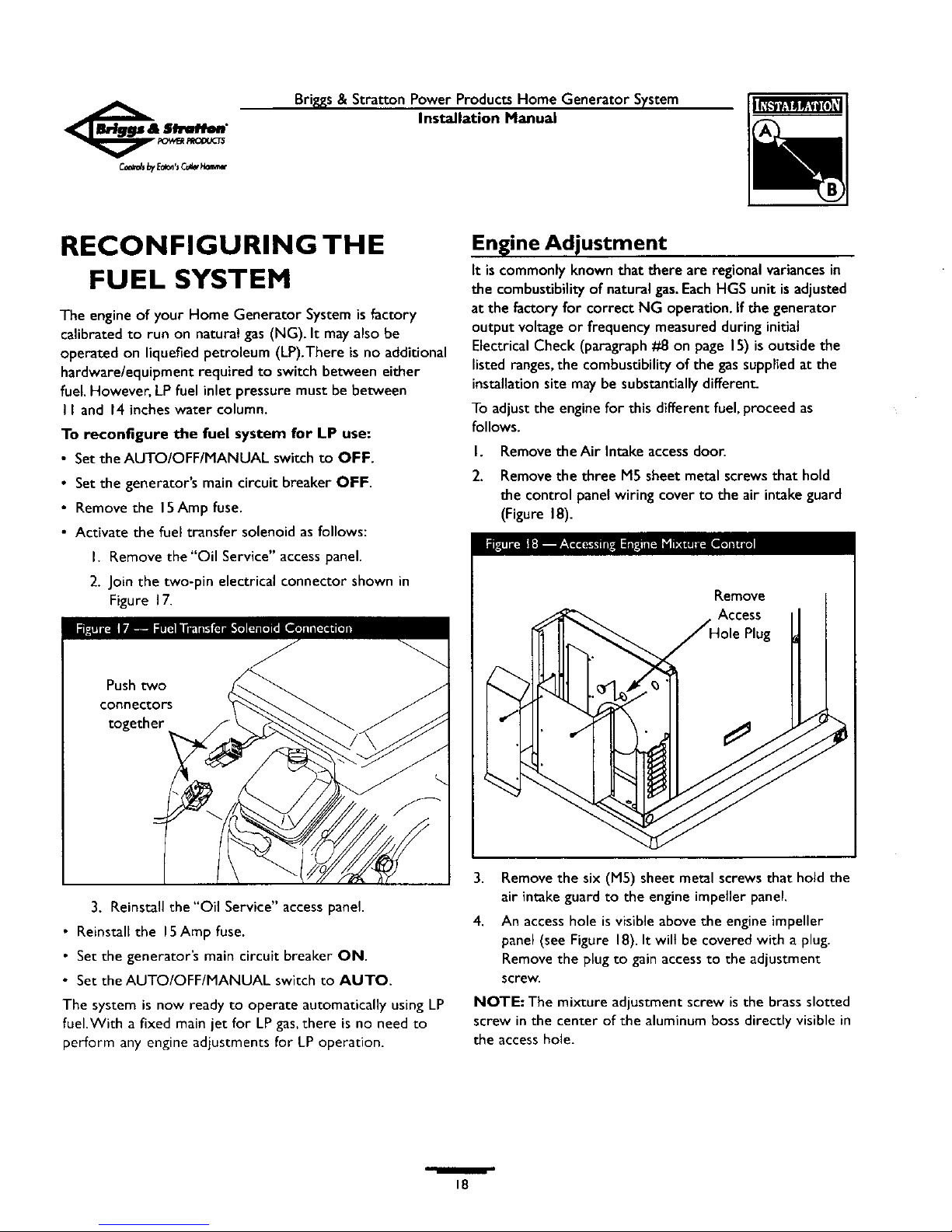
Engine Adjustment
It iscommonly knownthat there are regional variancesin
the combustibilityof natural gas.EachHGS unit isadjusted
at the factory for correct NG operation. If the generator
output voltageor frequency measuredduringinitial
ElectricalCheck (paragraph#8 on page IS) isoutsidethe
listedranges,the combustibilityof the gassupplied at the
installationsitemay be substantially different
To adjust the enginefor this different fuel,proceed as
follows.
I.
2.
Remove the Air Intake accessdoor.
Remove the three M5 sheet metal screws that hold
the control panel wiring cover to the air intake guard
(Figure 18).
,J
Remove
Access
Plug
3. Reinstall the "Oil Service" access panel
• Reinstall the 15Amp fuse.
• Set the generator's main circuit breaker ON.
• Set the AUTO/OFF/MANUAL switch to AUTO.
The system is now ready to operate automatically using LP
fuel.With a fixed main jet for LP gas, there is no need to
perform any engine adjustments for LP operation.
3,
4.
Removethe six (MS) sheet metal screws that hold the
air intakeguard to the engine impeller panel.
An accesshole isvisible above the engineimpeller
panel (see Figure 18).It wilt be covered with a plug.
Removethe plug to gainaccessto the adjustment
screw.
NOTE: The mixture adjustment screw is the brass slotted
screw in the center of the aluminum boss directly visible in
the access hole.
18
 Loading...