

Briggs & Stratton 1695360 Operator's Manual

Not for
Reproduction
ATTACHMENT
OPERATOR’S
MANUAL
42” 2-Stage Snowthrower
& Sub-frame
Mfg. No. Description
1695360 42” 2-Stage Snowthrower
1695196 Sub-frame Hitch
Briggs & Stratton Yard Power Products Group
Copyright © 2013 Briggs & Stratton Corporation
Milwaukee, WI USA. All Rights Reserved
1754620
Rev. H

Not for
Reproduction

Not for
Reproduction
Unpacking Recommendations ..................................................... 4
Hardware Bag / Hardware Contents ............................................ 5
Operator Safety ............................................................................. 8
Assembly ....................................................................................... 10
Assemble Hitch ......................................................................... 10
Assemble Push Bar Latch ......................................................... 10
Bracket Installation .................................................................... 11
Install Lift Lever Kit .................................................................... 11
Belt Installation .......................................................................... 11
Install Lock Plate
(Hydraulic Lift Models Only) .......................................................... 12
(Manual Lift Models Only) ............................................................. 12
Install Sub-Frame Hitch ............................................................. 12
Install Rear Lift Rod ................................................................... 13
Assembly Discharge Chute ....................................................... 14
Attach Deflector Control Cable Support Arm ............................. 15
Install Snowthrower ................................................................... 15
Install Front Lift Rod ................................................................... 15
Install Chute Rotator Switch
(Non-Electric Height-of-Cut Units) .................................................. 16
(Electric Height-of-Cut Units) ......................................................... 16
Install Wire Harness to Chute Harness ...................................... 17
Install Spring Anchor ................................................................ 18
Install Spring Anchor Assembly ................................................. 18
Mount Remote Deflector Control ............................................... 19
Rear Lift Rod Alteration ............................................................. 19
Install Drift Cutters ..................................................................... 19
Install Drive Belt ......................................................................... 20
Install Reflectors ........................................................................ 20
Required Accessories ................................................................... 21
Required Accessories ............................................................... 21
Recommended Accessories ..................................................... 21
Features & Controls ...................................................................... 22
Control Functions ...................................................................... 22
Tractor Controls ......................................................................... 22
Operation ....................................................................................... 23
Check Before Starting ............................................................... 23
Engine & Ground Speed Selection ............................................ 23
Starting & Stopping ................................................................... 23
Transporting .............................................................................. 23
Snow Removal Suggestions ...................................................... 24
Daily Storage ............................................................................. 24
................................................................... 24
Lift Variations When Using Attachments .................................... 25
Maintenance .................................................................................. 26
Schedule for Normal Care ......................................................... 26
General Lubrication ................................................................... 26
Check Auger Gearbox Oil Level ................................................ 26
Check Impeller Gearbox Oil Level ............................................. 26
Troubleshooting ............................................................................ 27
Troubleshooting Chart ............................................................... 27
Skid Shoe Adjustment ............................................................... 28
Electric Chute Rotator Gear ...................................................... 28
Auger Shear Pins ...................................................................... 28
Impeller Shear Bolt .................................................................... 28
Lift Assist Adjustment ................................................................ 29
Belt Tension Adjustment ............................................................ 29
Belt Replacement ...................................................................... 29
Template ......................................................................................... 30
Warranty ......................................................................................... 31
Table of Contents
NOTE: In these instructions, “front”, “back”, “left” and “right” are
referenced from the operating position.
3

Not for
Reproduction
Unpacking Recommendations
Hardware Bag Contents on Pages 5-8 are a combination of the kits below.
Please note the designated symbols for each kit when unpacking the contents.
It is recommended that hardware for each kit is kept separate during the assembly process.
s 1695196 Sub-Frame Hitch
l 1695360 42” 2-Stage Snowthrower
Hardware / Parts Identification
Lower case letters identify pre-assembled and / or pre-existing hardware / parts.
Upper case letters identify hardware / parts that are found in the kit (pages 5-7).
4
Not for
Reproduction
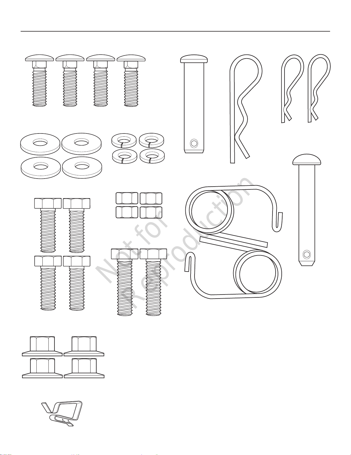
Hardware Bag Contents
A - CARRIAGE BOLT, s
5/16”-16 x 1.0” (Qty. 4)
B - WASHER, s
.312” ID x 1.0” OD x 13” THK (Qty. 4)
E - CAPSCREW, s
3/8”-16 x 1.0” (Qty. 4)
C - LOCKWASHER, s
5/16” (Qty. 4)
D - HEX NUT, s
5/16”-18 (Qty. 4)
H - CLEVIS PIN, s
.50” x 2.12” (Qty. 1)
L - SAFETY CLIP, s
I - HAIR PIN, s
(Qty. 1)
(Qty. 2)
J - HAIR PIN, s
(Qty. 2)
K - CLEVIS PIN, s
.375” x 2.375” (Qty. 1)
G - FLANGE NUT, s
3/8”-16 (Qty. 4)
O - CLIP WIRE, l
(Qty. 1)
F - CAPSCREW, l
3/8”-16 x 1.375” (Qty. 2)
M - CHUTE CONTROL
SWITCH,
(Qty. 1) l
N - CHUTE WIRE HARNESS, (Qty. 1) l
5
Not for
Reproduction
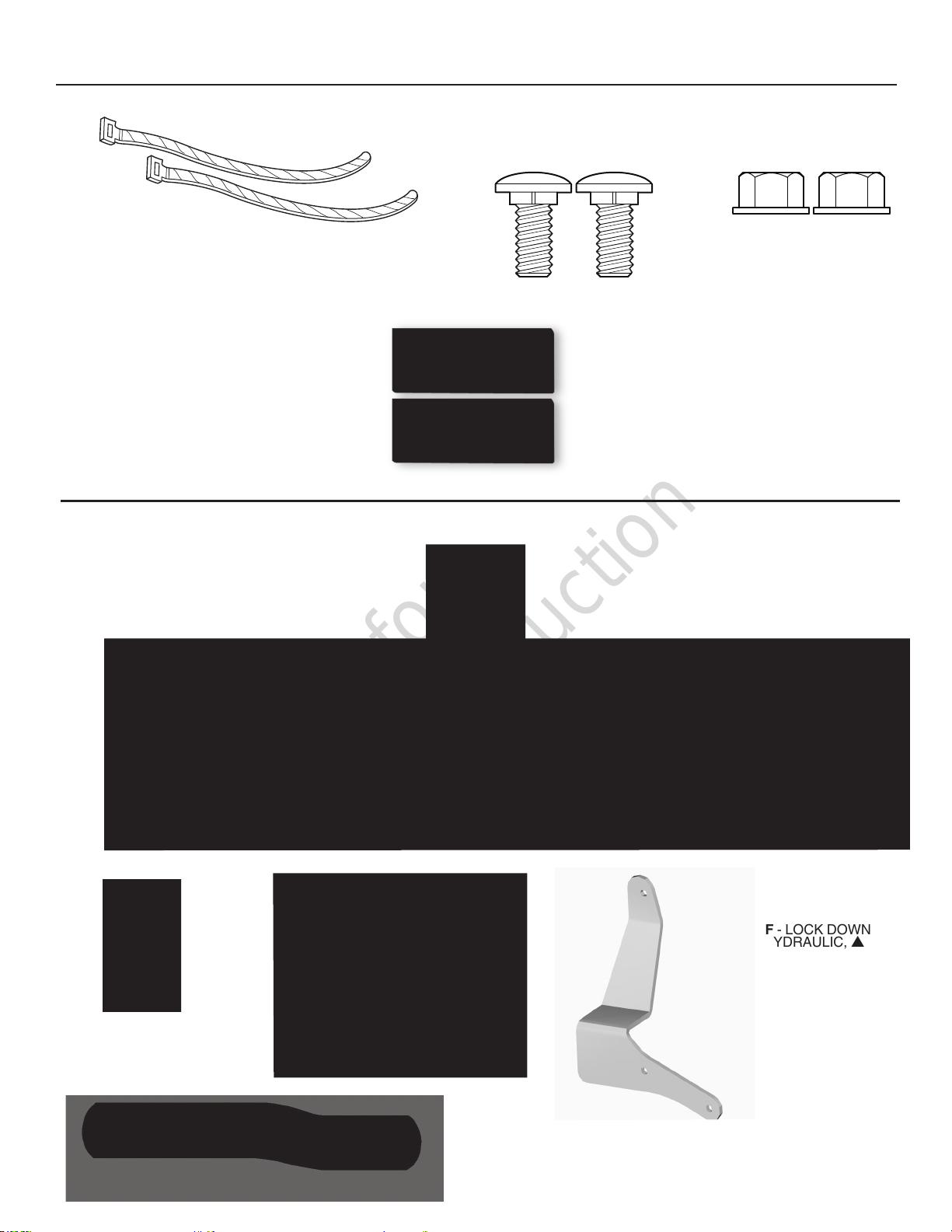
Hardware Bag Contents / Hardware
P - ZIP TIE, l
Qty. 2)
S - CARRIAGE BOLT, l
5/16”-18 x 3/4” (Qty. 2)
U -REFLECTORS, (Qty. 2) s
AA - SUPPORT CLAMP, s
T - FLANGE NUT, l
5/16”-18 (Qty. 2)
BB - PUSH BAR ASSEMBLY, s
CC - HOOK ASSEMBLY, s EE - SPRING ANCHOR, l
GG - LIFT BAR, s
DD - PUSH BAR LATCH, s
FF - LOCK DOWN
HYDRAULIC,
s
6

Not for
Reproduction
Hardware Bag Contents / Hardware
HH - LATCH ROD, s
LL - DISCHARGE
CHUTE ASSEMBLY,
l
KK - LIFT ROD ASSEMBLY, s
NN - SNOWTHROWER, l
JJ - LIFT LEVER ASSEMBLY, sII - HITCH ROD, Small, s
MM - DEFLECTOR CONTROL
CABLE SUPPORT ARM,
l
OO - HITCH PIN, s
PP - SPRING ANCHOR, l
TT - BELT, s
QQ - SPRING, l
RR - MOUNTING BRACKET ASSEMBLY, l
(NOTE: The mounting bracket assembly is attached to the
end of cable of discharge chute assembly LL).
SS - DRIFT CUTTERS, (Qty. 2) l
7
Not for
Reproduction
Operator Safety / SNOWTHROWERS
This snowthrower is capable of amputating hands and feet and throwing objects. Failure to observe the following
safety instructions could result in serious injury. Read these safety rules, and the safety rules in your tractor
Operator’s Manual, and follow them closely. Failure to obey these rules could result in loss of control of vehicle,
severe personal injury to yourself, or damage to property or equipment. The triangle in the text signifies
important cautions or warnings which must be followed.
Operator Safety
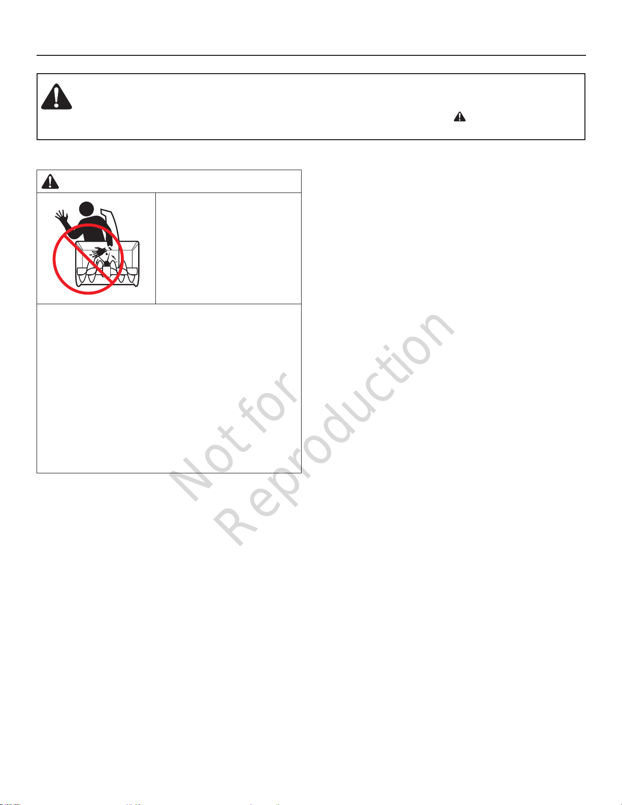
DANGER
Amputation hazard
The discharge chute
contains a rotating impeller
to throw snow. Fingers can
quickly become caught in
the impeller. Never clear or
unclog the discharge chute
with your hands. Always
use a clean-out tool.
Failure to observe these safety instructions will
result in traumatic amputation or severe laceration.
Hand contact with the rotating impeller inside the
discharge chute is the most common cause of injury
associated with snowthrowers. Never use your hands to
clean out the discharge chute.
To safely clear a clogged discharge chute, follow
these instructions:
1. Shut OFF the engine.
2. Wait 10 seconds to be sure the impeller blades have
stopped rotating.
3. Always use a clean-out tool, not your hands.
General
• Read this manual and the tractor Operator’s Manual
carefully. Be thoroughly familiar with the controls and
the proper use of the equipment.
• If snowthrower is equipped with a spring-assist tension
lever, never pull the spring-assist tension lever back
unless snowthrower is in fully raised position. The
spring is under tension when snowthrower is in lowered
position.
• Never allow children to operate the machine. Do not
allow adults to operate it without proper instruction.
• Do not carry passengers.
• Keep the area of operation clear of all persons,
particularly small children, and pets.
• Never direct discharge chute towards bystanders.
• Make sure all hardware is secure and that snowthrower
is in good operating condition.
• Check to be sure all safety devices and shields are in
place.
• Check that all adjustments are correct before using this
unit.
Preparation
• Never attempt to make any adjustments while engine is
running.
• Thoroughly inspect the area where the snowthrower is
to be operated and remove all foreign objects.
• Adjust the skid shoe height to clear gravel or crushed
stone surface. See the Maintenance and Adjustments
section for procedure.
• One wheel weight on each rear wheel or rear weights is
required.
Operation
• Exercise extreme caution when operating on, or
crossing, gravel drives, walks or roads. Stay alert for
hidden hazards or traffic.
• Never allow anyone in front of the machine while it is
operating.
• After striking an object or if unit starts to vibrate
abnormally, stop the engine, disengage the PTO, and
remove the key. Check for the cause and any dam-age
before restarting. Before any inspection, make sure all
moving parts have stopped.
• Take all possible precautions before leaving operator’s
position. Disengage the PTO, lower the attachment, set
the parking brake, stop the engine and remove the key.
• Never operate the snowthrower near glass enclosures,
automobiles, window wells, dropoffs, etc., without
proper adjustment of discharge angle.
• Do not overload machine capacity by attempting to
clear snow at too fast a rate.
• Never operate unit at high transport speeds on slippery
surfaces. Use care when travelling in reverse.
• Disengage power to snowthrower when transporting or
not in use.
• Never operate the snowthrower without good visibility
or light. Always be sure your feet are properly placed on
the footrests and keep a firm hold on the steering wheel.
8
Not for
Reproduction
WARNING
1756841
Perform the Safety System Interlock test found in your
tractor Operator’s Manual. If tractor does not pass the
test, do not operate the tractor. See your authorized
dealer. Under no circumstances should you attempt to
defeat the safety system.
Operating on Slopes
WARNING
• Never operate on slopes greater than 10°.
• Select slow ground speed before driving onto a
slope. Avoid using brakes to control speed.
• Drive up and down the face of the slopes, never
across the slope face.
• Use caution when changing directions and DO NOT
START OR STOP ON A SLOPE.
Operator Safety / SNOWTHROWERS
Recommended Accessories
Tire chains are recommended when installing this
attachment to your unit.
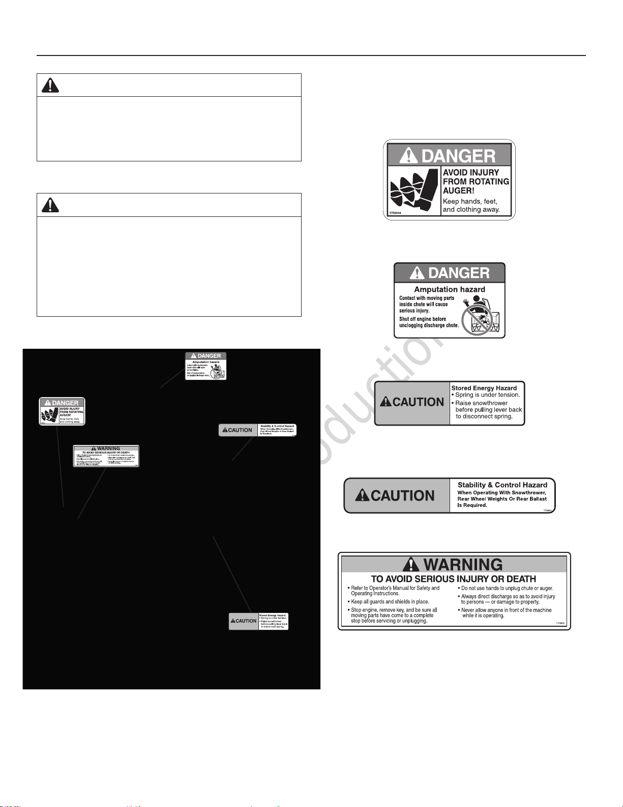
Safety Decals
Part No. 1756838
Danger Decal - Auger
1756841
Part No. 1756841
Danger Decal - Discharge Chute
1756842
Part No. 1756842
Caution Decal - Spring Tension
(If equipped with spring-assist tension lever.)
Part No. 1756840
Caution Decal - Stability & Control
1756842
Part No. 1756839
Warning Decal - Avoid Injury
9
Not for
Reproduction
Assembly
WARNING
Before beginning any service work turn off the PTO, set
the parking brake, turn off the ignition, and disconnect
the spark plug wire(s).
Refer to “Tractor” operating manual for mower removal.
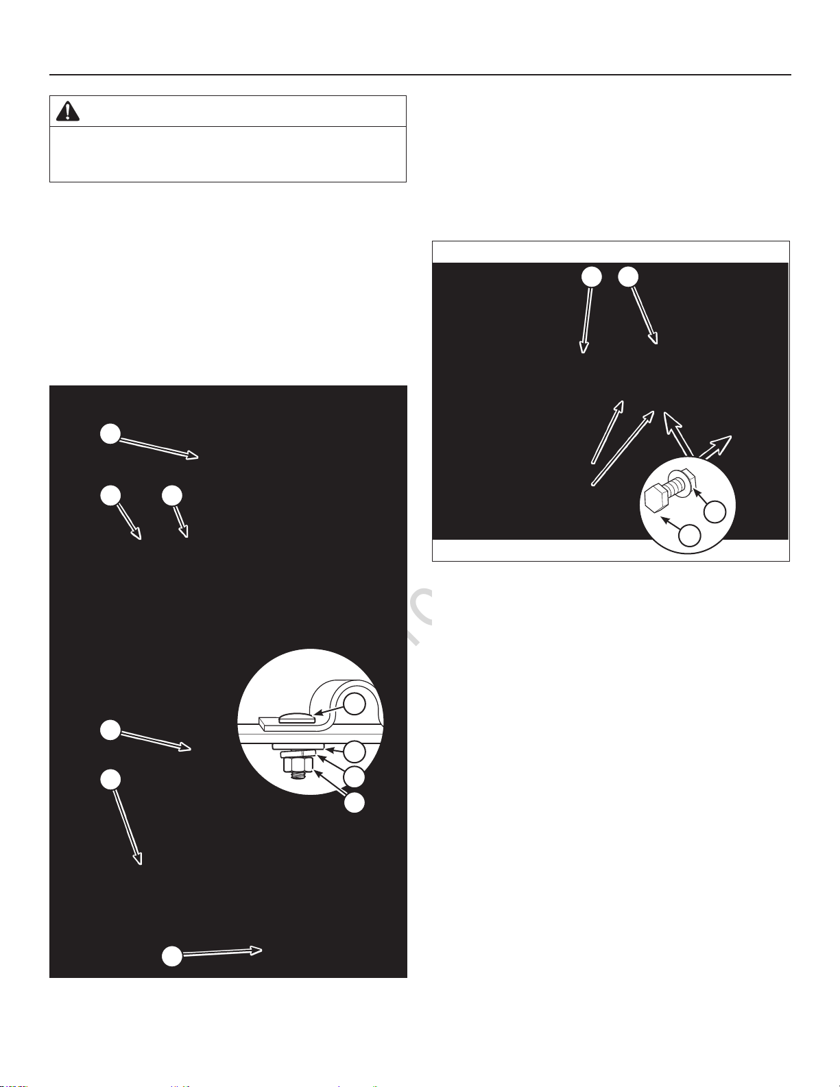
Assemble Hitch
1. Attach the support clamp (AA, Figure 1) to the subframe hitch (BB) with carriage bolts (A), washers (B),
lockwashers (C), and nuts (D). Support clamp should
be able to slide. Do not tighten the hardware at this
time. It will be tightened in Step 6 of “Install SubFrame Hitch.”
2. Insert hook assembly (CC) into support clamp.
Conquest, Prestige & CTX 9500
CC
AABB
Assemble Push Bar Latch
For 2012 Models & Previous Years
1. Attach push bar latch (DD, Figure 2) onto each side of
sub-frame hitch (BB). Secure with capscrews (E) and
nuts (G) on both sides.
NOTE: Refer to Figure 2 for four wheel drive and two
wheel drive push bar latch placement.
BB
DD
4 Wheel Drive
2 Wheel Drive
G
Broadmoor & CTX 9000
CC
BB
E
Figure 2
A
B
C
D
AA
Figure 1
10
 Loading...