

Briggs & Stratton 90000, 100000 Series, 90000 Series Operating & Maintenance Instructions
BRIGGS
Operating & Maintenance
Instructions
Model Series
Covered in
This Manual
90000
100000
[Model
Type Code
1
Note: General Model Series numbers noted above are inclusive of the specific model
number found on your engine. To get replacement parts or technical assistance in
the future, write your engine Model, Type, Code and date of purchase here. fl°ith/ _aY ( Yiar
TABLE OF CONTENTS
Safety ................................. 3-5
Engine Information ........................ 6
Oil ....................................... 7
Fuel ..................................... 8
Starting Information ....................... 9
Starting and Stopping ..................... 10
Maintenance ......................... 11-13
Adjustments ............................. 14
Parts and Service & Storage ............ 15-16
Warranty Information ..................... 17
WARNING
Briggs & Stratton does not approve or authorize the use of
these engines on 3-wheel All Terrain Vehicles (ATVs), motor
bikes, aircraft products or vehicles intended for use in
competitive events. Use of these engines in such applications
could result in property damage, serious injury (including
paralysis), or even death.
PRINTED iN U.S.A. c_)Copyright 2003 by Briggs & Stratton Corporation FORM NO. 275508-5/03
The Power That Works For You. TM
Thank you for selecting a Briggs & Stratton engine to power your equipment.
Briggs & Stratton is committed to producing a line of engines which will make your life's chores easier to
perform. We have, at the same time, improved the design of our engines so they are environmentally
friendly. Since 1995, we have succeeded in reducing smog-forming exhaust emissions from our engines
by 70%. Briggs & Stratton's efforts have not stopped there. We are also committed to designing and
introducing even cleaner engines in the future, while maintaining our reputation for excellent utility and
value.
Briggs & Stratton's environmental awareness has resulted in the engineering of the "Smart-Fillc_" gas
can, featuring a spill resistant nozzle which opens only when fully inserted into the gas tank, and which
shuts off automatically when the tank is full. Because refueling spills can harm the environment, the
Smart-Fill_e container helps preserve a stronger ecosystem by reducing this source of pollution.
We hope you will enjoy your new engine and equipment. We welcome you to our worldwide family of
Briggs & Stratton engine users.
Best Wishes Always,
The Employees of Briggs & Stratton Corporation
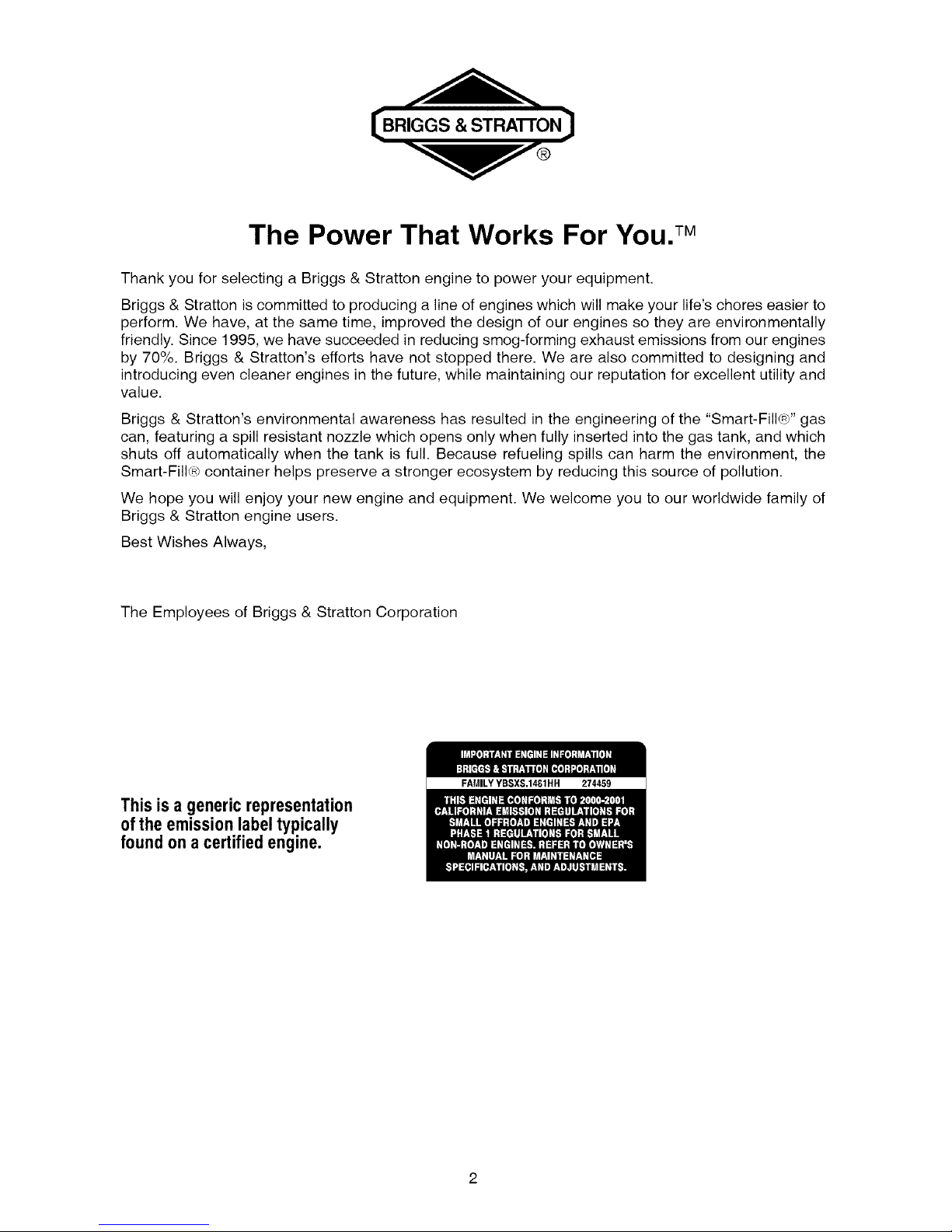
This is a generic representation
of the emissionlabel typically
found on a certified engine.
FAMILYYBSXS.14_1HH 274459
I, _ F_]I BEFORE OPERATING ENGINE
• Read entire Operating & Maintenance Instructions AND
the instructions for the equipment this engine powers.*
• Failure to follow instructions could result in serious injury
or death.
275508
THE OPERATING & MAINTENANCE INSTRUCTIONS
CONTAIN SAFETY INFORMATION TO
• Make you aware of hazards associated with engines
• Inform you of the risk of injury associated with those hazards, and
• Tell you how to avoid or reduce the risk of injury.
\
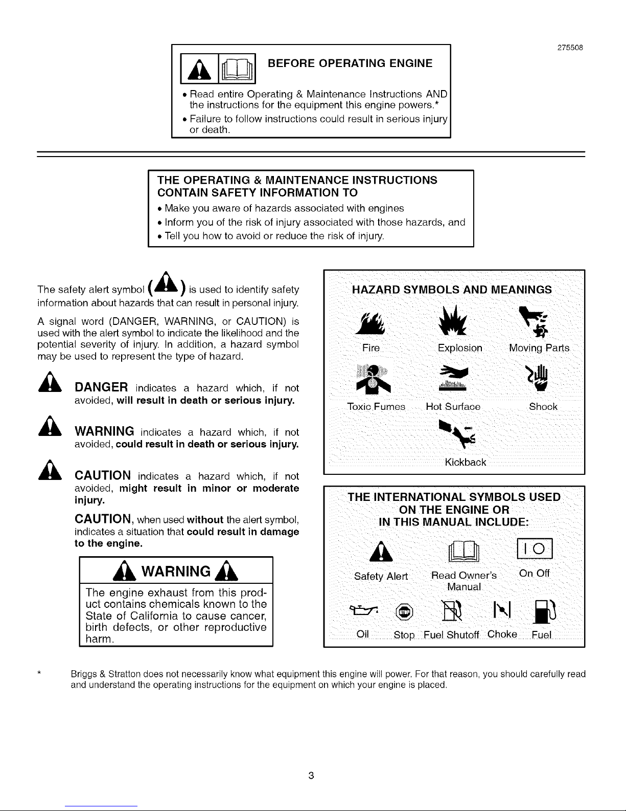
The safety alert symbol _m,lL ) is used to identify safety
information about hazards that can result in personal injury.
A signal word (DANGER, WARNING, or CAUTION) is
used with the alert symbol to indicate the likelihood and the
potential severity of injury. In addition, a hazard symbol
may be used to represent the type of hazard.
_k DANGER indicates a hazard which, if not
avoided, will result in death or serious injury.
_, WARNING indicates a hazard which, if not
avoided, could result in death or serious injury.
CAUTION indicates a hazard which, if not
avoided, might result in minor or moderate
injury.
CAUTION, when used without the alert symbol,
indicates a situation that could result in damage
to the engine.
WARNING
The engine exhaust from this prod-
uct contains chemicals known to the
State of California to cause cancer,
birth defects, or other reproductive
harm.
HAZARD SYMBOLS AND MEANINGS
Fire Explosion Moving Parts
Toxic Fumes Hot Surface Shock
Kickback
THE INTERNATIONAL SYMBOLS USED
ON THE ENGINE OR
Oil Stop Fuel Shutoff Choke Fuel
Briggs & Stratton does not necessarily know what equipment this engine will power. For that reason, you should carefully read
and understand the operating instructions for the equipment on which your engine is placed.
SAFETY [B,, Gs STRA O.]
, WARNING
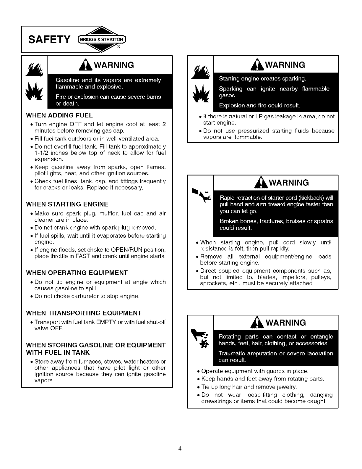
WHEN ADDING FUEL
• Turn engine OFF and let engine cool at least 2
minutes before removing gas cap.
• Fill fuel tank outdoors or in well-ventilated area.
• Do not overfill fuel tank. Fill tank to approximately
1-1/2 inches below top of neck to allow for fuel
expansion.
• Keep gasoline away from sparks, open flames,
pilot lights, heat, and other ignition sources.
• Check fuel lines, tank, cap, and fittings frequently
for cracks or leaks. Replace if necessary.
WHEN STARTING ENGINE
• Make sure spark plug, muffler, fuel cap and air
cleaner are in place.
• Do not crank engine with spark plug removed.
• If fuel spills, wait until it evaporates before starting
engine.
• If engine floods, set choke to OPEN/RUN position,
place throttle in FAST and crank until engine starts.
WHEN OPERATING EQUIPMENT
• Do not tip engine or equipment at angle which
causes gasoline to spill.
• Do not choke carburetor to stop engine.
WHEN TRANSPORTING EQUIPMENT
• Transport with fuel tank EMPTY or with fuel shut-off
valve OFF.
WHEN STORING GASOLINE OR EQUIPMENT
WITH FUEL IN TANK
• Store away from furnaces, stoves, water heaters or
other appliances that have pilot light or other
ignition source because they can ignite gasoline
vapors.
, WARNING
• If there is natural or LP gas leakage in area, do not
start engine.
• Do not use pressurized starting fluids because
vapors are flammable.
, WARNING
• When starting engine, pull cord slowly until
resistance is felt, then pull rapidly.
• Remove all external equipment/engine loads
before starting engine.
• Direct coupled equipment components such as,
but not limited to, blades, impellors, pulleys,
sprockets, etc., must be securely attached.
, WARNING
• Operate equipment with guards in place.
• Keep hands and feet away from rotating parts.
• Tie up long hair and remove jewelry.
• Do not wear loose-fitting clothing, dangling
drawstrings or items that could become caught.
I B. GS ST.A O.JSAFETY
WARNING
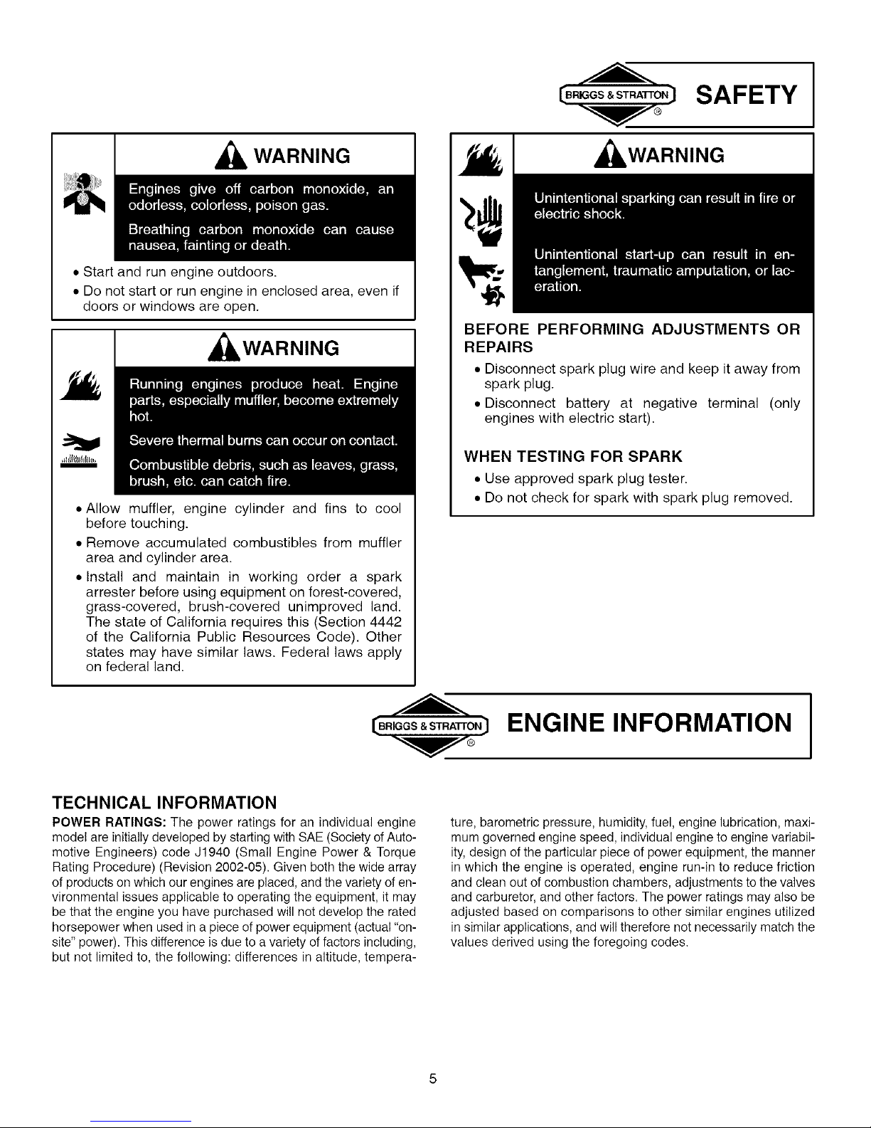
• Start and run engine outdoors.
• Do not start or run engine in enclosed area, even if
doors or windows are open.
WARNING
i
• Allow muffler, engine cylinder and fins to cool
before touching.
• Remove accumulated combustibles from muffler
area and cylinder area.
• Install and maintain in working order a spark
arrester before using equipment on forest-covered,
grass-covered, brush-covered unimproved land.
The state of California requires this (Section 4442
of the California Public Resources Code). Other
states may have similar laws. Federal laws apply
on federal land.
, WARNING
;>lJill
I
ill=
BEFORE PERFORMING ADJUSTMENTS OR
REPAIRS
• Disconnect spark plug wire and keep it away from
spark plug.
• Disconnect battery at negative terminal (only
engines with electric start).
WHEN TESTING FOR SPARK
• Use approved spark plug tester.
• Do not check for spark with spark plug removed.
[ BRIG S&StrA'rrorJENGINE INFORMATION
I
TECHNICAL INFORMATION
POWER RATINGS: The power ratings for an individual engine
model are initially developed by starting with SAE (Society of Auto-
motive Engineers) code J1940 (Small Engine Power & Torque
Rating Procedure) (Revision 2002-05). Given both the wide array
of products on which our engines are placed, and the variety of en-
vironmental issues applicable to operating the equipment, it may
be that the engine you have purchased will not develop the rated
horsepower when used in a piece of power equipment (actual "on-
site" power). This difference is due to a variety of factors including,
but not limited to, the following: differences in altitude, tempera-
ture, barometric pressure, humidity, fuel, engine lubrication, maxi-
mum governed engine speed, individual engine to engine variabil-
ity, design of the particular piece of power equipment, the manner
in which the engine is operated, engine run-in to reduce friction
and clean out of combustion chambers, adjustments to the valves
and carburetor, and other factors. The power ratings may also be
adjusted based on comparisons to other similar engines utilized
in similar applications, and wil! therefore not necessarily match the
values derived using the foregoing codes.
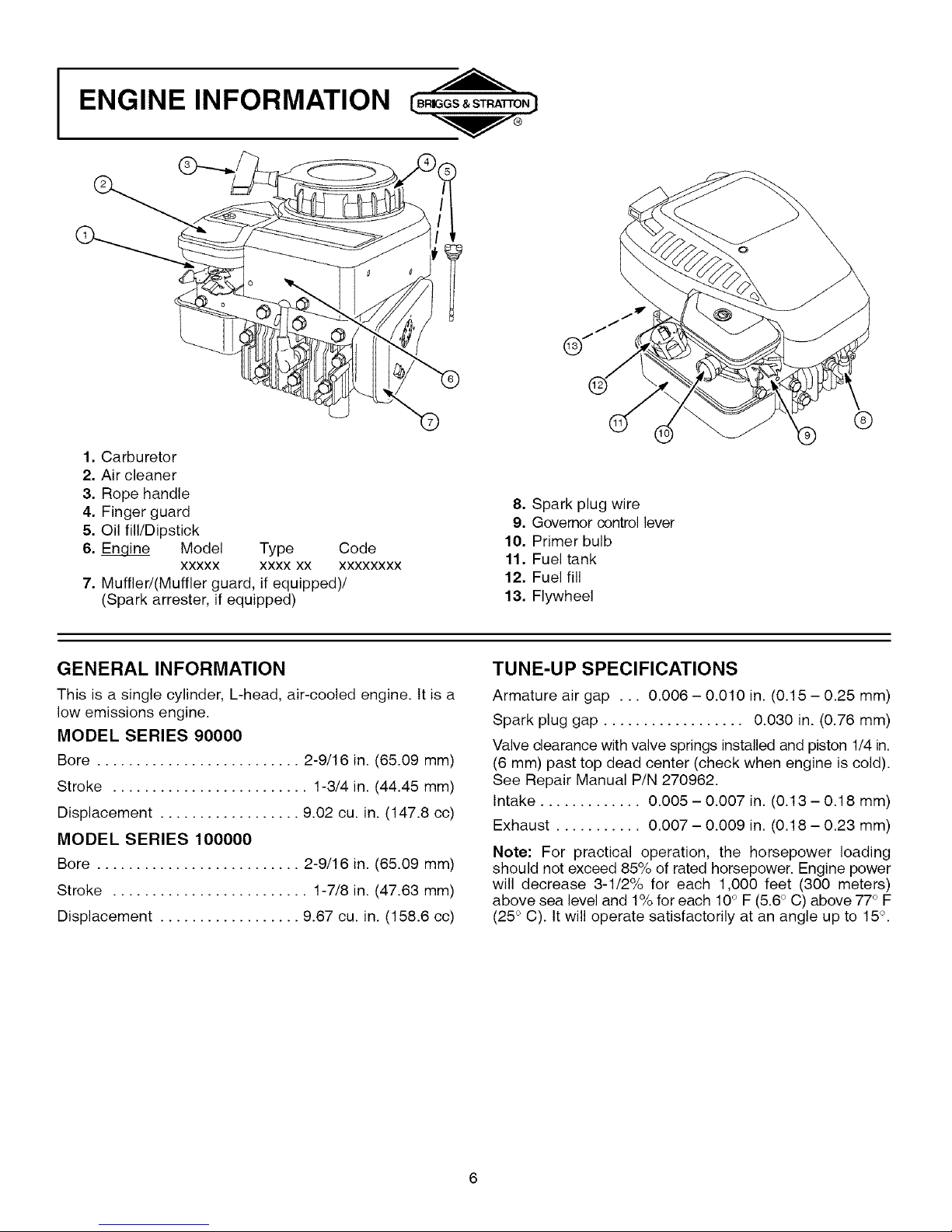
I ENGINE INFORMATION
1. Carburetor
2. Air cleaner
3. Rope handle
4. Finger guard
5. Oil fill/Dipstick
6. Enoine Model Type Code
XXXXX XXXX XX XXXXXXXX
7. Muffled(Muffler guard, if equipped)/
(Spark arrester, if equipped)
8. Spark plug wire
9. Governor control lever
10. Primer bulb
11. Fuel tank
12. Fuel fill
13. Flywheel
GENERAL INFORMATION
This is a single cylinder, L-head, air-cooled engine. It is a
low emissions engine.
MODEL SERIES 90000
Bore .......................... 2-9/16 in. (65.09 mm)
Stroke ......................... 1-3/4 in. (44.45 mm)
Displacement .................. 9.02 cu. in. (147.8 cc)
MODEL SERIES 100000
Bore .......................... 2-9/16 in. (65.09 mm)
Stroke ......................... 1-7/8 in. (47.63 mm)
Displacement .................. 9.67 cu. in. (158.6 cc)
TUNE-UP SPECIFICATIONS
Armature air gap . .. 0.006 - 0.010 in. (0.15 - 0.25 mm)
Spark plug gap .................. 0.030 in. (0.76 mm)
Valve clearance with valve springs installed and piston 1/4 in.
(6 mm) past top dead center (check when engine is cold).
See Repair Manual P/N 270962.
Intake ............. 0.005 - 0.007 in. (0.13 - 0.18 mm)
Exhaust ........... 0.007 - 0.009 in. (0.18 - 0.23 mm)
Note: For practical operation, the horsepower loading
should not exceed 85% of rated horsepower. Engine power
will decrease 3-1/2% for each 1,000 feet (300 meters)
above sea level and 1% for each 10° F (5.6° C) above 77° F
(25 ° C). It will operate satisfactorily at an angle up to 15°.
 Loading...