

Briggs & Stratton 138400, 086400, 118400, 085400, 235400 User Manual
...
Briggs & Stratton
VANGUARD
™
SINGLE CYLINDER OHV AIR-COOLED ENGINES
1/07
Quality Starts With A
Master Service Technician
272147 - Vanguard Single Cylinder OHV Air-Cooled Engines
272144 - Vanguard Twin Cylinder OHV Air-Cooled Engines
275429 - Vanguard Twin Cylinder OHV Liquid-Cooled Engines
MS-0750 - Vanguard 3-Cylinder OHV Liquid-Cooled Gasoline Engines
MS-1055 - Vanguard 3-Cylinder OHV Liquid-Cooled Diesel Engines
Other Briggs & Stratton
Commercial Power Repair Manuals:
Vanguard Single Cylinder
OHV Air-Cooled Engines
™
POST OFFICE BOX 702
MILWAUKEE, WI 53201 USA
BRIGGSandSTRATTON.COM
©2007 Briggs & Stratton Corporation
BRIGGS&STRATTON
CORPORATION
Part No. 272147-1/07
272147 Vanguard Single Cylinder 4/27/07 1:03 PM Page 1

SECT ION 1- Saf ety, Maintenance & Adjustments
SECT ION 2 -Troubles hooting
SECTION 3 - En gine Disa ssembly
SECTION 4 - Exhaust Systems
SECTION 5 - Fuel Systems & Carburetion
S ECTION 6 - Governor Systems
SECTION 7- Cylinder Heads & Valves
1
2
3
4
5
6
7
SECTION 8 - Starters
SECTION 9 - Lubrication Systems
S ECTION 10 - Cylinders, Covers & Sumps
SECTION 11 - Crankshafts, Camshafts, Balancing Systems &
Gear Reducti ons
SECTION 12 - Pistons, Rings & Connecti ng Rods
SECTION 13 - Final Engine Assem bly
SECTION 14 - Engin e Specifications & Reference Tables
8
9
10
11
12
13
14

FORWARD
This guide has been written and published by Br iggs & Stratton Corporation to aid our dealers' mechanics
and company service personnel when servici ng the products described herein.
It is assumed th at these personnel are familiar with the servicing procedures for these products, or like or
similar products, manufactured by Briggs & Stratton Corporation. It is also assumed that they have been
trained in the r ecommended servicing procedures for these products, which includes the use of mechanics
hand tools and any special tools that might be required.
Proper service and repair is important to th e safe , econo mical and reliable operation of all engines and
engine driven systems. The troubleshooting, testing, service and repair procedures desc ribed in this guide
are effec tive methods of performing such oper ations.
We could not possibly know of and advise the service trade of all conceivable procedures or methods by
which a servi ce might be performed, nor of ever y possible hazards and/or results of each procedure or
method. We have not undertaken any such wide evaluation. Therefore, anyone who uses a procedure or
method not described by the manufactu rer must first satisfy himself that neither his safety, nor the safety of
the product, will be endangered by the service or operating procedure selected.
All information, illustrations, and specifications contained in this guide are based on the latest production
information available at the time of publication . However, Briggs & Stratton Corporation reserves the right
to change, alter, or oth erwise improve the product at any time without prior notice.
Some components or assemblies of the product described in this guide may not be con sidered repairab le.
Disassembly, repair and reassembly of such compo nents may not be included in this guide.
C opyrigh t © 2008 Briggs & Stratton Cor poration
All rig hts reserved.
No part of this material may be reproduced or transmitted, in any form or by any means, electronic or
mechanical, including photocopying, recording or by any information storage and retrieval system, w ithout
prior permission in writ ing from Briggs & Stratto n Corporat ion.

SECTION 1 - SAFETY, MAINTENANCE AND ADJUSTMENTS
ENGINE SAFETY ..... ............................................................................ 5
In Th e Interest Of Safety ........................ ............................. 5
The Safety Alert Symbol............................................................. .......... 5
Additional Precautions..........................................................................8
BRIG GS & STRATTO N NUMERIC AL IDENTIFICATIO N SYSTEM..... 9
ENGINE MAINTENANCE...................................................................10
Fuel and Oil Recommen dations............................... ...................... ..... 10
Changing Oil.......................................................................................11
MAINTENANCE SCHEDULE............................................................. 12
Air Cleaner Service............................................................................. 13
In-Line Fuel Filter Service................................................................... 15
ENGINE ADJUSTMENTS .................................................................. 15
Armature Air Gap Adjustments................................ ...........................15
Carburetor Idle-Mixture Adjustments.................................................. 15
Control Adjustments ...........................................................................16
Cooling System Maintenance............................................................. 18
Flywheel Brake Adjustments (104700)...............................................19
Governor Adjustments........................................................................19
Electro-Magnetic Idle Down Adjustments ...........................................25
Spark Plug Maintenance.....................................................................26
Valve Clearance Adjustments.............................................................26
Combustion Chamber Deposits........................................................ . 27
1
3

1
4
ENGINE SAFETY
engines is such applications could result in
In The Interest Of Safety
This repair manual contains safety information
that is designed to:
• Make you aware of hazards associated
with engines.
• Inform you of the risk of injury associated
with those hazar ds.
• Tell you how to avoi d or reduce the risk
of injury.
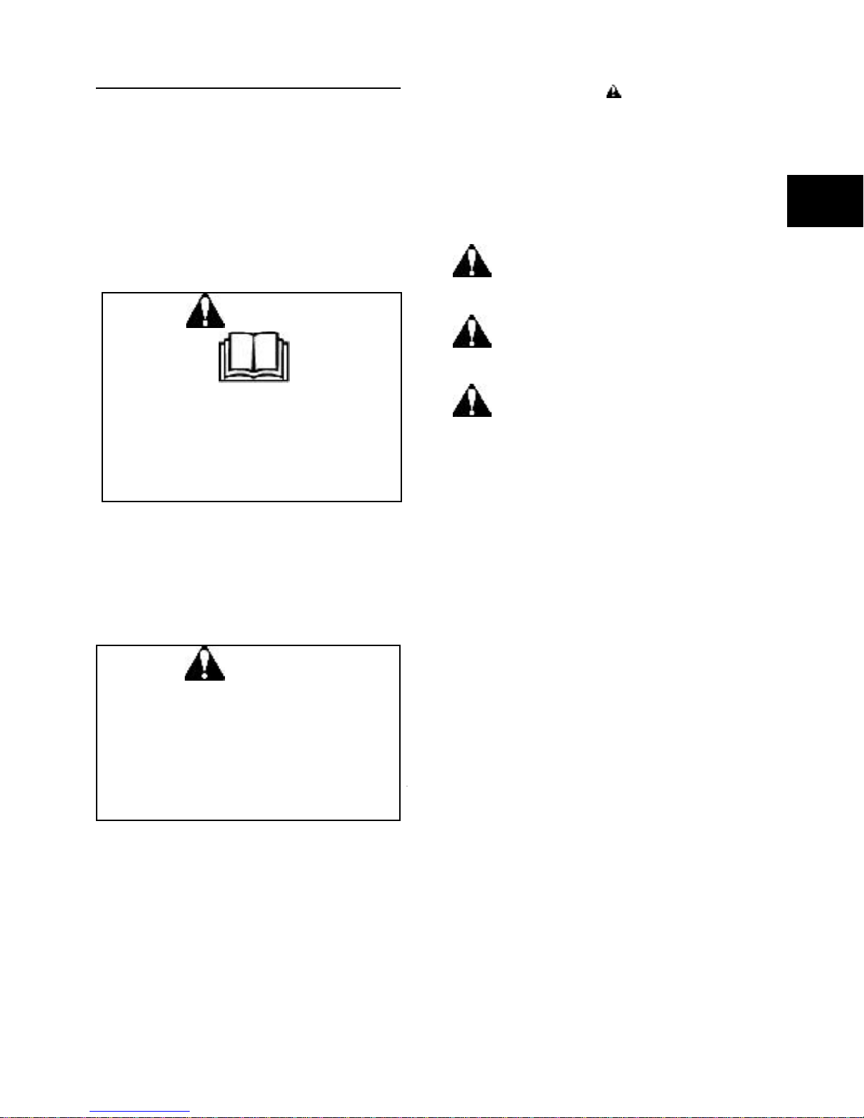
The Saf ety Alert Symbol
The safety alert symbol ( ) is used to identify
safety information about hazards that can result
in personal inj ury.
A signal word (DANGER, WARNING, or CAUTION)
is used with the alert symbol to indicate the
likelihood and the potential severity of injury. In
addition, a hazard symbol may be used to
represent the t ype of hazard.
DANGER indicates a hazard which, if
not avoided, will result in death or
serious injury.
1
WARNING
•
Before attempting to service this
equipment, read and understand this
manual and the operating instructions of
the equipment it powers.
Failure to FOLLOW instructions could result in
DEATH, SERIOUS INJURY
paralysis) or pr opert y dam age.
(includi ng
WARNING
Briggs & Stratton does not approve or
authorize th e use of these engines on 3wheel All Terrain Vehicles (ATV’s) ,
motorbikes, fun/recreational vehicles for
use in competitive events. Use of these
property damage, serious injury (including
paralysis), or even death.
WARNING indicates a hazard which, if
not avoided, could result in death or
serious injury.
CAUTION indicates a hazard which, if
not avoided, might result in minor or
moder ate injury.
CAUTION: When this signal word is used
without the alert symbol, it indica tes a situation
that could result in damage to the engine.
• Prior to work, read and understand the
section(s) of this manual that pertain to
the job. Follow all safety warnings.
• Wear sui table eye protection.
• When servicing engines or equipment,
prevent accidental starti ng by remo ving
the spark plug wire from the spark
plug(s).
• Disconnect ne gative battery terminal if
the application is equipped with an
electric startin g system.
• Periodically clean engine. Keep governor
parts free of dirt, grass and other debris
which can affect engine speed and
cooling.
• Always use fresh gasoline. Stale fuel can
cause gum deposits in the carbure tor
and cause leakage, flow restrictions or
other failure s.
• Check fuel lines and fittings frequently for
cracks or leaks and replace if necessary.
5
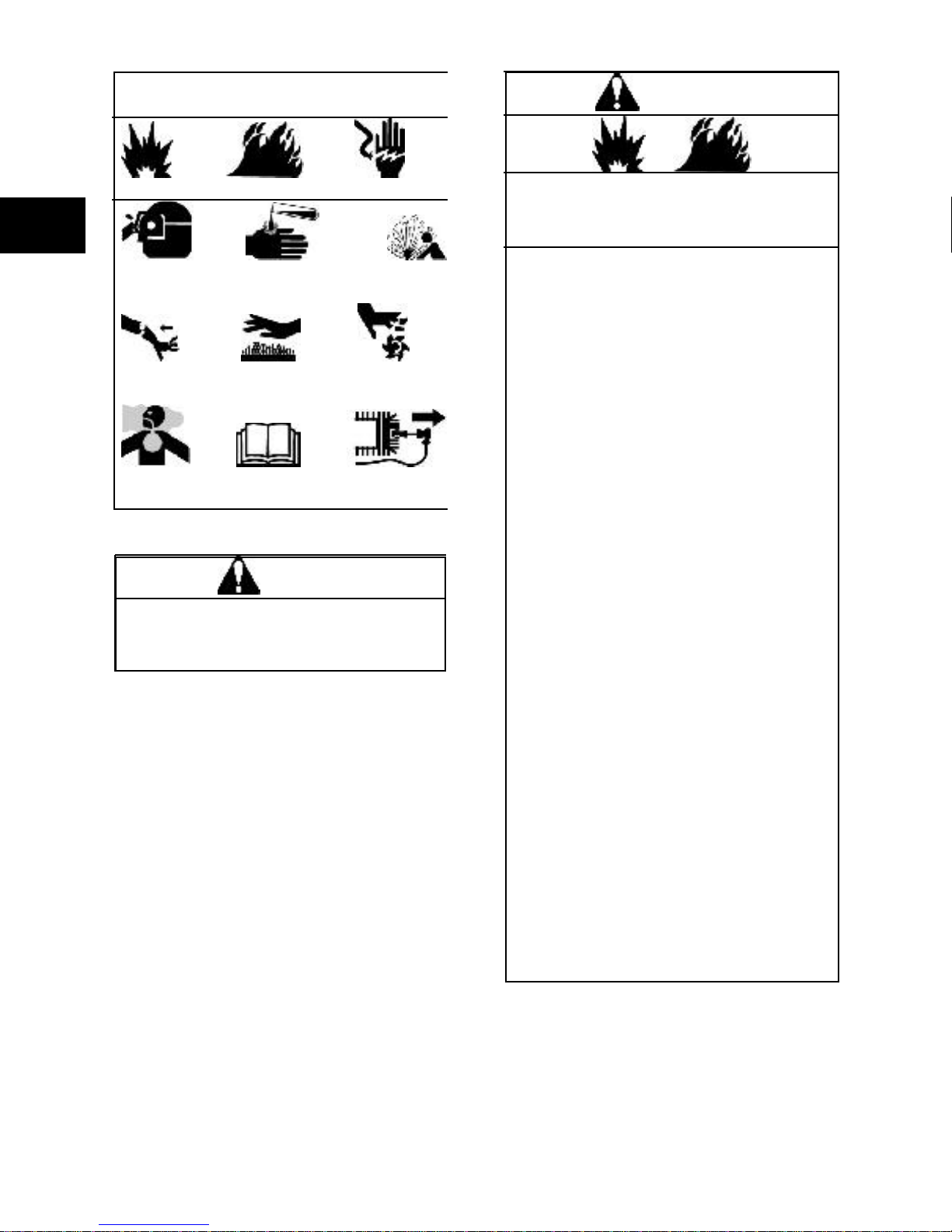
HAZAR D SYMBO LS AND
Toxic Read Disconnect
Fumes Spark Plug
and other reproductive harm.
MEANINGS
WARNING
1
Explosion Fire Shock
Goggles Chemical Explosive
Burns Pressure
Kick Hot Entanglement
Back Surface
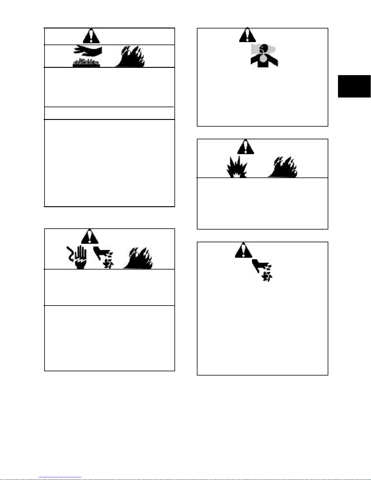
W AR NING
The engine exhaust from this product
contains chemicals known to the State of
California to cause cancer, birth defects
Gasoline and its vapors are extremely
flammable and explosive.
Fire or explosion can cause severe burns or
death.
When adding fuel:
• Turn engine
least 2 minu tes before filling or refillin g.
• Fill fuel tank outdoors or in a wellventilated area.
• Do not overfill fuel tank. Fi ll tank to
approxi mately 1- 1/2 inches below top
of neck to allow for fuel expansion.
• Keep gasoline away from sparks, open
flames, pilot lights, heat and other
ignition sources.
Check fuel lines, tank, cap and fittings
•
frequentl y for cracks or leaks and
replace if necessary.
When starting engine:
• Make sure spark plug , muffler, fuel cap
and air cleaner are in place.
• Do not crank engine with spark plug
removed.
• If fuel spills, wait until it evaporates
befor e star ting engine .
If engine floods, set choke to
•
OPEN/RUN
and crank until engine starts.
FAST
When operating equipment:
Do not tip engine or equipment at an
•
angle which would cause fuel to sp ill.
Do not choke carburetor to stop
•
engine.
When transporting equipment:
• Transpor t with fuel tank empty or with
fuel shut-off valve set to OFF.
When storing gasoline or equipment with
fuel in tank:
and let engine cool at
OFF
position. Place throttle in
• Store away from furnaces, stoves,
water heaters or other appliances that
have a pilot light or other ignition
source because they can ignite
gasolin e vapors .
6
DANGER
Running engines p ro duce heat.
Temperatur e of muffler and surrounding
areas can exceed 150°F (65°C). Severe
burns can occur on contact.
Allow muffler, engine cylinder fins and
•
radiator to cool before touching.
• Remove accumulated combustib les
from m uffler area and cylind er are a.
• Install and maintain in working order a
spark arre stor before using equ ipment
on forest-covered, brush -covered
unimproved land. The state of
California requires this (Section 4442
of the Public Resources Code). Other
states may have similar laws. Federal
laws apply on feder al land.
DANGER
Engin es give off carbon monoxide, an
odorless, colorless, poison gas.
Breathing carb on monoxide can cause
nausea, fainting or death.
• Start and run engine out doors.
• Do not start or run engine in an
enclosed area, even if doors and
windows are open.
DANGER
Starting engine creates sparking. Spa rking
can ig nite nearby flammable gases.
Explosion and fire could result.
• If there is a natural or LP gas leakage
in the area, do not start engine.
• Do not use pressurized starting fluids
because vapors are flammable.
1
WARNING
Unintentional sparking can result in fire or
electric shock.
Unintentional start-up can result in
entang lement, t raumatic amputation or
severe lacerations.
Before performing adjustments or repairs:
Disconnec t spark plug wire and keep it
•
away from spark plug.
Disconnec t negative (-) battery
•
termin al.
When test ing for spa rk:
• Use approved spark plug tester.
Do not check for spark with spark plug
•
removed.
DANGER
Rotating parts can contact or entangle
hands, feet, hair, clothing or accessories.
Traumatic amputation or severe lacerations
can result.
• Operate equipment with guards in
place.
• Keep hands and feet away from
rotating parts.
Tie up long hair and remove jewelry.
•
• Do not wear loose-fitting clothin g,
dangling drawstrings or items that
could become entangled in the
equipment.
7

1
WARNING
Charging batteries produces hydrogen gas.
Do not store or charg e and battery near an
open flame or devices that utilize a pilot
light or can create a spark.
WARNING
Kerosene and its vapors are extreme ly
flammable and should be handled with the
same precautions as gasoline.
DANGER
Broken bones, fractures, bruise s or sprai ns
could re sult.
• Remove al l external equipment/engine
loads before starting engine.
• Direct-coupled equipment components
such as, but not limited to blades,
impeller s, pulleys and sprockets must
be securely attached.
WARNING
All f uel components should b e in good
conditio n and proper ly maintained.
• Repairs should only be made with
factory approved parts.
• Repair work should be done by a
qualified technici an.
• Flexible supply lines should be
checked regularly to make sure they
are in good condition.
8
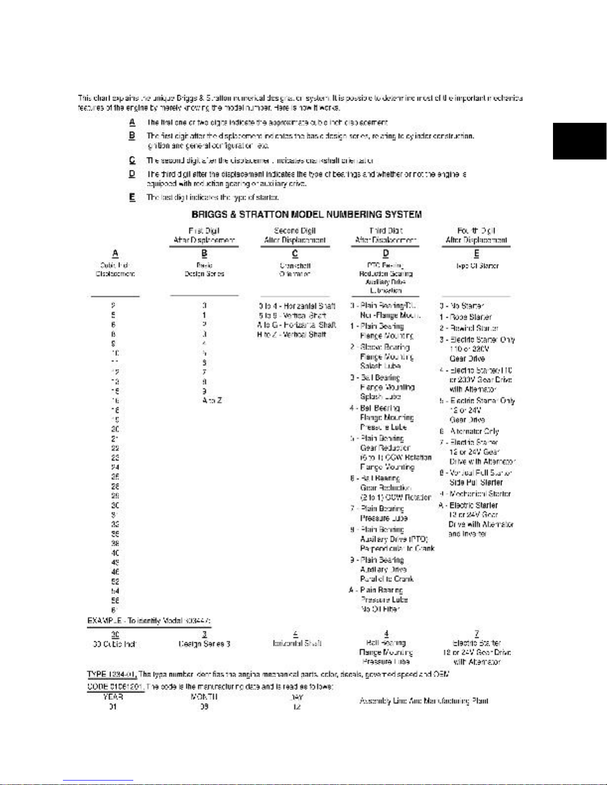
BRIGGS & STRATTON NUMERIC AL
IDEN TIFICATION SYSTEM
1
9

1
ENGI NE MAINTENANCE
Fu el and Oil Recommendations
Fuel
Fuel must meet these requirements:
• Use clean, fresh unleaded gasoline.
• A minimum of 87 octane / 87 AKI (91
RON). For high altitude use, see “High
Altitude” below.
• Gasoline with up to 10% ethanol
(gasohol) or up to 15% MTBE (Methyl
Tertiar y Bu tyl Eith er) is accepta ble.
CAUTION: Do not use unapproved gasoline
such as E85. Do not mix in gasoline or modify
the engine to run on alternate fuels. This will
damage the engine components and void the
engine warranty.
To protect the fuel system from gum formation,
mix a fuel stabilizer into the gasoline see
“Storage” below. All fuel is not the same.
If starting or performance problems occur:
• Change fuel providers or change brands.
High Altitude
At altitudes over 5000 feet (1524 meters), a
minimum of 85 octane / 85 AKI (89 RON)
gasoline is accepta ble. To remain emissions
compli ant, high al titude adjustm ent is r equire d.
Operati on w ithout this adjustment will cause
decreased perform ance, increased fuel
consumption and increased emiss ions.
At altitudes below 2500 feet (762 meters), high
alti tude adju stment i s not recommended.
Storage
Fuel can become stale when stored over 30
days. Stale fuel causes acid and gum deposits to
form in the fuel system and/or on essential
carburetor parts. To keep fuel fresh, use Briggs
& Stratton FRESH START™ (#5041) fuel
stabilizer, availabl e as a liquid additive or a drip
concentrate cartr idge.
There is no need to drain gasoline from the
engine before storage if fuel stabilizer is added
according to instructions. Run the engine for two
minutes to circulate the stabilizer throughout the
system. The engine and fuel can then be stored
for up to 24 mon ths.
If gasoline has not been treated with a fuel
stabilizer prior to storage, it must be drained from
the engine into an approved container. Run the
engine until it stops from lack of fuel. The use of
a fuel stabilizer in the storage container is
recommend ed to maintain freshness.
CAUTION: Some fuel, called “oxygenated” or
“reformulated” gasoline, is gasoline blended with
alcohol or eth er. Excessive amounts of these
blends can damage the fuel system or cause
performance problems. If any undesirable
operating sym ptoms occur, use ga soline with a
lower percentage of alcohol or ether.
Oil
Oil has four purposes:
• It cools
• It cleans
• It seals
• It l ubricates
During normal operation, small particles of metal
from the cylinder w alls, pistons, bearings as well
as normal combustio n deposits will gradually
contaminate the oil. Dust particles from the air
also contaminate the oil. This forms an abrasive
mixture that can cause wear to the internal parts
of the engine if the oi l is not changed regularly.
Fresh oil also assists in cooling. Old oil gradually
becomes thick and loses its cooling ability as
well as its lubricating qualities.
Use a high quality detergent oil classified “For
Service SF, SG, SH, SJ” or higher. Use synthetic
oil such as Briggs & Stratton (#100074) or
equivalen t. If synthetic oil is not available, Briggs
& Stratton non-synthetic 30 weight oil (#100005 or
#100028) is an acceptable substitute. Do not use
special additives with recommended oils.
Do not mix oil with gasoline.
10
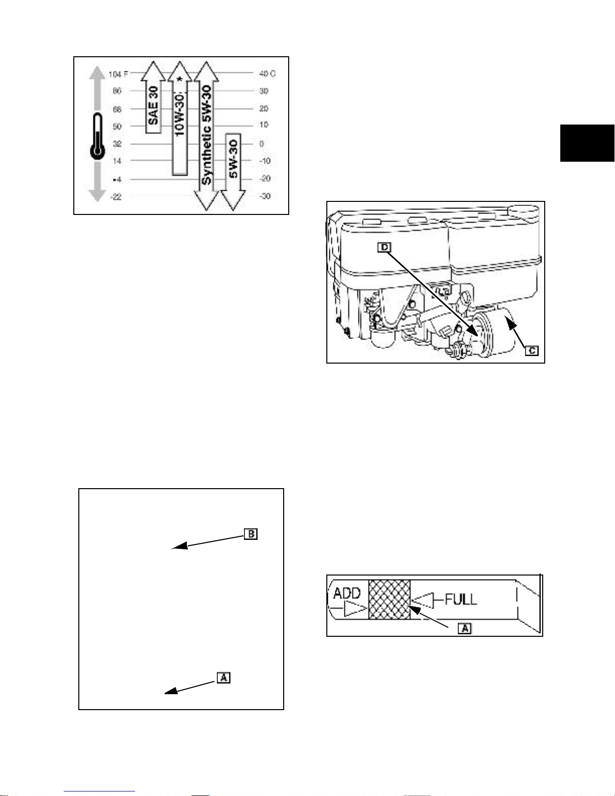
Fig. 1
CAUTION: The use of non-synthetic multi-
viscosity oils (5W-30, 10W-3 0, etc.) in
temperatures above 40°F (4°C) will result in
higher th an nor mal oil consumption. When using
a multi-viscosity oil, check oil level more
frequentl y. SAE 30 oil, i f used below 40°F (4°C),
will result in hard starting and possible engine
bore damage due to inadequate lubrication.
1. Park equipment so engine is level.
2. Remove oil drain plug ([A] Fig. 2).
• Dr ain oil while engine is still warm.
3. Install drain plug. Torq ue to value listed.
SEE SECTION 14- ENGINE SPECIFICATIONS.
4. Remov e oil filter ([ C] Fig. 3), if equipped.
• Clean surface of fi lter mounting adaptor
([D] Fig. 3).
• Apply light coa t of clean engine oil to new
filter gasket.
1
NOTE : The use of synthetic oils does not alter
the oil change intervals.
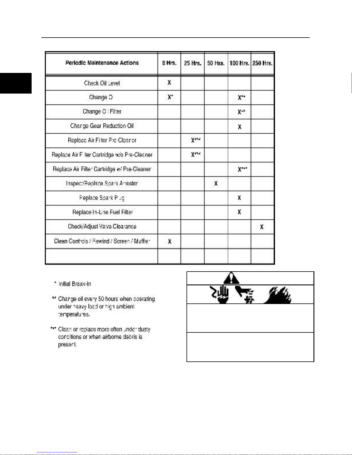
C hanging Oil
Change oil and filter (if equipped) after the first 58 hours. Thereafter, change oil every 100 hours
of operation.
Change oil mor e ofte n if engi ne is op erated in
dirty or dusty conditions or if engine is operated
under heavy loads and/or in high ambient air
temperatures.
Fig. 3
5. Screw filter on by hand until gasket
contacts oil fi lter mounting adapter. Then
tighten an additional 1/2 to 3/4 turn .
6. Clean area around oil fill cap and tube ([B]
Fig. 2).
7. Fill with the correct amount of new oil.
SEE SECTION 14- ENGINE SPECIFICATIONS.
Start engine and run at idle for a minute or so.
8. Shut engine off and wait for oil to settle
back into the cylinder.
9. Check dipstick. If necessary, add more oil
slowly to bring oil level to FULL mark ([A]
Fig. 4) on di pstick.
Fig. 4
Fig. 2
CAUTION: Do not overfill. Overfilling can cause
seals to fail or overheating due to oil foaming.
10. Replace oil fi ll cap and dipstick.
11. Start and run engine. Check for oil leaks.
11
1
MAINTENA NCE SCHEDULE
12
WARNING
Unintentional sparking can result in fire or
electric shock.
Unintentional start-up can result in
entanglement, traumatic amputation or
severe lacerations.
Before performing adjustments or repairs:
•
Disconnect spark plug(s).
• Disconnect negative (-) battery cable.
• Use only the correct tools.
Air Cl eaner Servic e
CAUTION: Never operate an engine with the air
cleaner assembly or air cleaner cartridge
removed.
A correctly serviced air cleaner protects internal
engine parts from airborne dirt and dust part icles.
If air cleaner instructions are not followed,
particles that should be collected in the air
cleaner will pass int o the engine. These particles
are abrasive and will cause the piston rings and
cylinder bore to wear more quickly. As the rings
and bore wear , th e particles enter the cyli nder
and contaminate the oil. This forms an abrasive
mixture that will erode and damage internal
engine compone nts.
Prevent dirt and dust from entering the engine
through improper sealing.
• Replace worn or damaged air cleaner
gaskets and seals.
• Replace air cl eaner mounting brackets if
bent or damaged.
Remove Air Cleaner Assembly
1. Follow steps 1 through 3 listed previously.
2. Remove screws and nuts holding air
cleaner base (F) to carburetor and/or
control bracket.
3. Pull air cleaner base away from
carburetor.
4. Disconnect breather tube (G) from air
cleaner base or rocke r cover.
Fig. 5
1
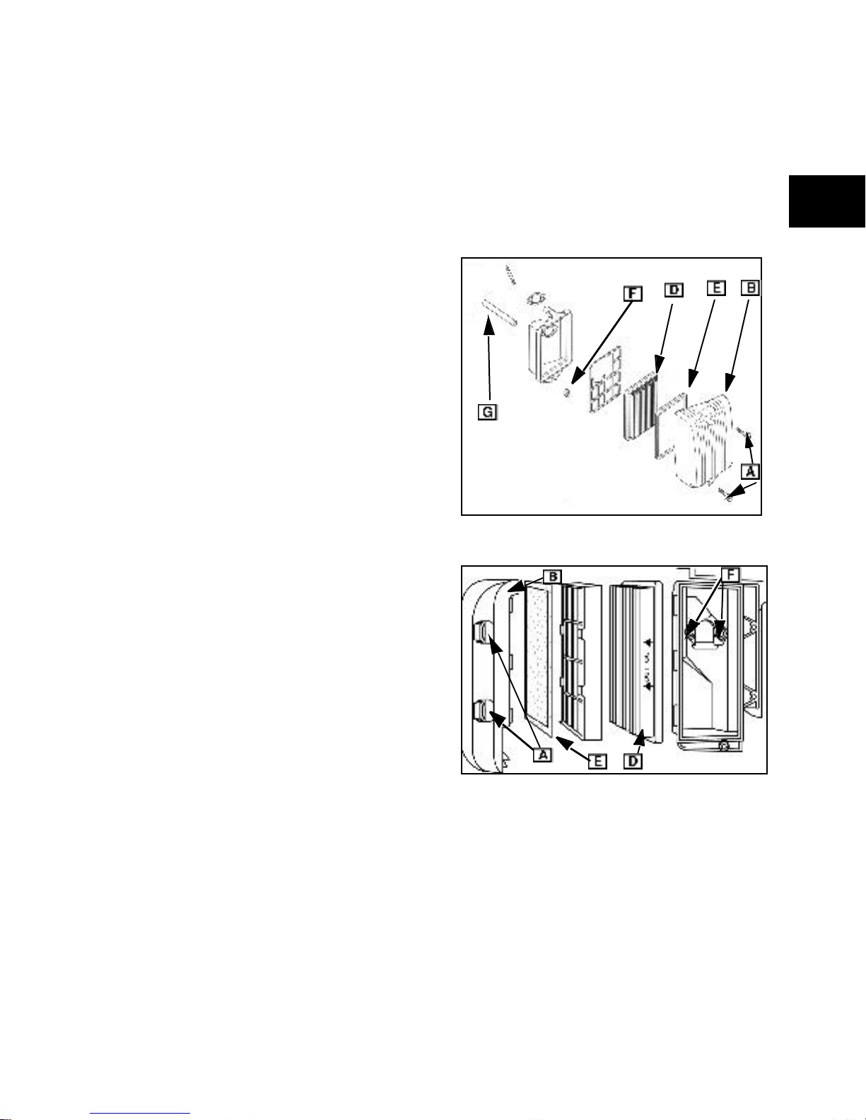
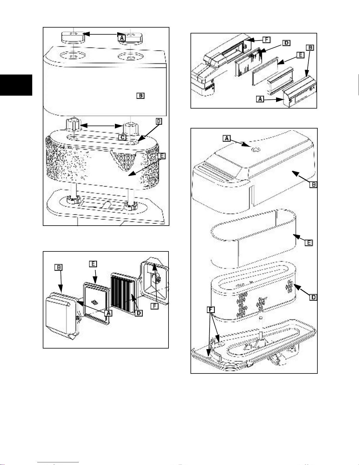
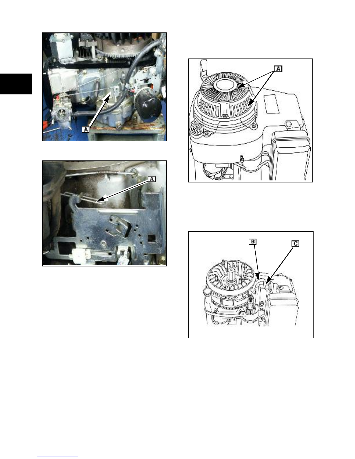
Cle aning and Replacing Air Filters
Refer to Figures 5-10 that show the air cleaner
for your engine.
1. Loosen screws or knobs (A) holding air
cleaner cover in place and remove cover
(B).
2. Carefully clean debris f rom the base and
cover, then remove air filter element
retaining nut (C) (if equipped).
3. Lift off filter element (D ) with the pre-
cle aner (E) (if so equipped).
4. Wash pre-cleaner in warm soapy water.
5. Rinse and dry thoroughly.
6. Saturate pre-cleaner in fresh clean engine
oil and squeeze out excess. (Do not oil
pre-cleaners labeled DO NOT OIL. )
Replace pre-cleaner if no longer
serviceable.
7. Gently tap filter element on a solid surface
to dislodge debris. Replace filter element
if very dirty or damaged.
8. Reinstall pre-cleaner , element , retai ning
nut(s), cover and screws.
Fig. 6
CAUTION: Do not use pressurized air or
solvents to clean filter elements. Pressurized air
can damage elements and solvents might
dis solve fi lter mesh.
13
1
Fig. 9
Fig. 7
Fig. 8
14
Fig. 10
Install Air Cleaner Assembly
1. Connect breather tube to back side of air
cleaner base.
2. Position base (with new gasket) on
carburetor.
NOTE: Use new screws with sealant band or
place non-hardening sealant on mounting
screws.
3. Start screws into carburetor and tighten
securely.
4. Install air clean er element and/or precleaner.
In-Line Fuel Filter Service
Replace in-line fuel filter every year or 100 hours
of operation, whichever occurs first. Replace the
filter if dirt or water are present. Refer to the
correct illustrated parts list (IPL) that applies to
your engine for the correct filter.
ENGINE ADJUSTMENTS
Armatu re Air Gap Adju stments
1. Rotate flywheel until magnets are away
from armatu re.
2. Loosen both armature mounting screws
(A) and pull armature away from flywheel.
3. Snug one screw.
4. Insert the proper thickness gauge ([B] Fig.
11) between armature and flywheel.
SEE SECTION 14- ENGINE SPECIFICATIONS.
5. Turn flywheel. Loos en screws and allow
the magnets to pull armature against
thickness gauge ([B] Fig. 11).
6. Tighten screws to listed values. See on
page 255.
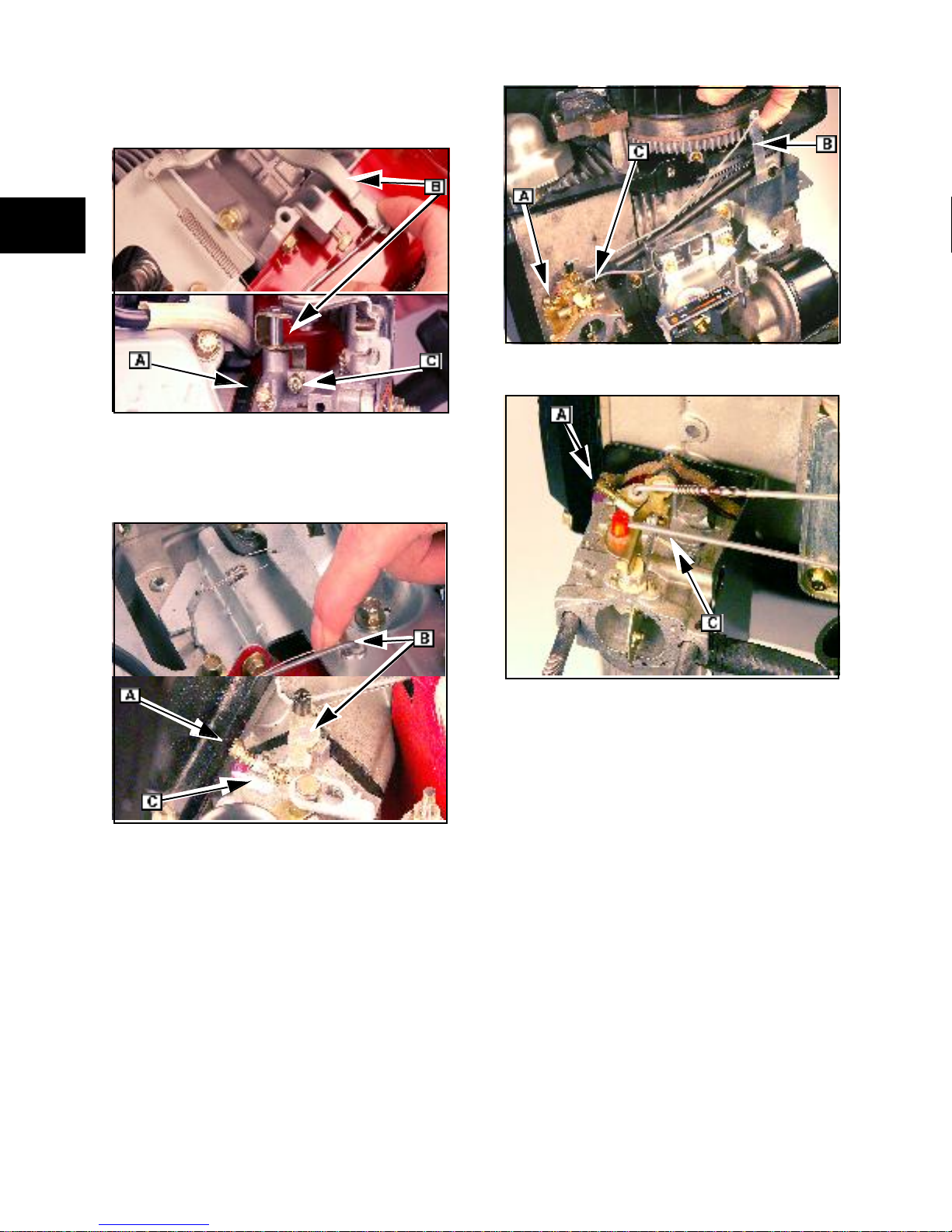
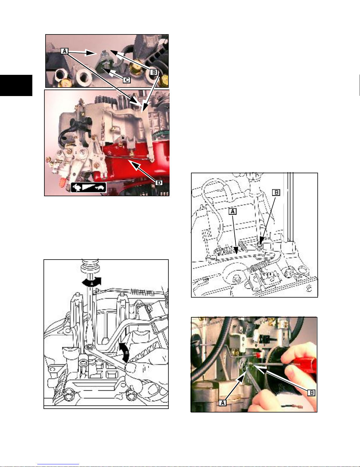
C arburetor Idle-Mixture Adjustments
Initial Mixt ure Adjustmen t
Refer to the figure that shows your engine.
1. Turn the idle mixture screw ( [A] Fig. 12) in
until you feel it just make contact with the
seat.
2. Back the idle mixture screw out 1-1/4
turns.
3. Start the engine and let run at half throttle
for 5 minutes to bring it up to operating
temperature.
1
Fig. 11
Adjusting Idle Mixture RPM
Refer to the figure that shows your engine.
NOTE: Parts removed for clarity.
1. Move throttle to SLOW.
2. While holding the speed control lever (B)
against the idle speed screw, ad just the
idle speed screw (C) to obtain 1750 RPM,
except as noted for the following models:
• Model 104700: 1500 RPM
• Models 161400, 260700, 261700: 1200
RPM
• Models 085400, 086400, 115400,
117400, 118400, 185400: 1300 RPM
3. Turn idle mixture screw ( A) clo ckwise
(CW) until the engine just begi ns to slow.
4. Turn idle mixture screw counterclockwise
(CCW) until the engine just begins to
slow.
15
1
5. Turn idle mixture screw back to midpoint
and release the speed control lever.
6. Install limiter cap (if equipped) using
knockout pin (#19135).
Fig. 14
Fig. 12
NOTE: (138400) Does not have an idle
adjus tment scr ew.
Fig. 13
Fig. 15
7. Move speed control from SLOW to FAST.
If the engine does not accelerate smoothly:
• Adjust idle mixture screw 1/ 8 turn CCW.
8. Check idle RPM and readjust to
specifica tions, i f req uired.
C ontrol Adjustme nts
Throttle Control
(050000, 085400, 086400, 115400, 117400,
118400, 138400, 185400, 235400, 245400,
28Q700)
The throttle controls on these units are
interco nnected with th e gover nor linkage system.
SEE SECTIO N 6- GOVERN OR SYSTEMS.
16
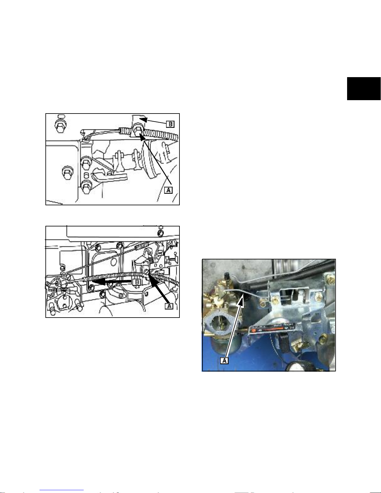
Throttle Control
(161400, 104700, 260700, 261700)
Refer to Figures 16 and 17 that show your
engine.
1. Loosen casing clamp screw (A).
2. Move throttle to FA ST .
3. Move casing in direction of arrow (B) until
casing stops.
4. Tighten casing clamp screw.
Fig. 16
Choke-A-Matic®
(104700, 161400, 2607 00, 261700,
28Q700)
Choke control cables are often provided by the
original equipment manufacturer. Please refer to
the i nformation provided by the OEM when this
general description is not sufficient to adjust the
choke control.
1. Loosen choke control casing clamp screw
on engine control panel or gove rnor
control bracket.
2. Move choke control l ever or kno b to
CHOKE.
3. Move choke control casing in the direction
that completely closes the choke valve.
4. Tighten the casing cl amp screw.
Choke-A-Matic® Adjustments (161400)
Refer to the figure that shows your engine.
1. Move thrott le control to FAST. The end of
the choke link should contact the end of
the choke lever slot. To adjust, expand or
contract loop (A ) in the choke link.
2. Move equipment control lever to CHOKE.
The choke plate must be closed. Readjust
as req uired.
1
Fig. 17
Choke Co ntrol
(050000, 085400, 086400, 115400, 117400,
118400, 138400, 185400, 235400, 245400)
The choke on these models has a separate
manual contr ol.
Ensure that the choke valve is completel y open
or closed when the control is moved through its
range of m otion.
Fig. 18
17
1
Clean the static screen ([A] Fig. 21)
.
Fig. 19
Fig. 21
Clean the ducting (B) and cylinder fins ([C] Fig.
22), yearly or every 100 hours of operation. Clean
more often when dust or airborne debris is
present.
Fig. 20
C ooling System Maint enance
CAUTION: Keep engine parts clean to reduce
the risk of overheatin g and ignition of
accumulated debris.
Do not use water to clean engine. Water could
contaminate fuel system and short out electrical
systems. Low pressure (5-10 psi.) compressed
air may be used.
Grass partic les, chaff, or dirt can clog the air
cooling system, especially after prolonged
service in very dusty conditions or when cutting
dry grass. Continued operatio n with a clogged
cooling system can cause severe overheating
and possible engine damage.
18
Fig. 22

Fly wheel Brake Adjustments
(104700)
The flywheel brake system is part of a safety
control mechan ism required by some equipment
applications. When the operator releases an
equipment control (bail) with the engine running
at theFAST selection, the flywheel brake must
stop the engine within 3 seconds.
WARNING
DANGER
Engines give off carbon monoxi de, an
odorless, colo rless, poison gas.
Breathing carbon monoxide can cause
nause a, fain ting or d eath.
• Start and run engine outdoors.
• Do not start or run engine in an
enclosed area, even if doors and
windows are open.
1
Unintentional sparking can result in fire or
electric shock.
Unintentional start-up can result in
entang lement, t raumatic amputation or
severe lacerations.
Before performing adjustments or repairs:
Disconnec t spar k plu g(s).
•
• Disconnect negative (-) battery cable.
• Use only the correct tools.
Using torque wrench#19393 and a socket to fit
the flywheel nut, turn the flywheel clockwise
( CW) with the brake engaged. Turning at a
steady rate, the torque reading should be the
listed value. SEE SECTION 14- ENGINE
SP ECIFICA TIONS.
If the reading is low:
• Check the thickness of the brake pad.
• Replace brake lever and pad if the brake
pad thickness is less than0.090 in.
(2.29mm).
If the pad is with in specification:
• Adjust the control cable casing anchor to
posi tion the pad closer to the flywheel
when the safety control is in RUN.
If correct adjustment cannot be made:
• Replace the brake assembly.
Governor Adjustments
CAUTION: C omplete the governor static
adj ustment before starting or r unning engin e.
In correct adjustment could result i n engine overspeedi ng causing engine damage.
NOTE: (161432-0080-01,161430-0199-01,
185430-0099-01, 185430-0140-01, 1854300299-01) These engine models are equipped
with governors supplie d by equipment
m anufacturers. Consult with the OEM for service
procedures on these model/types.
A complete governor system adjustment
includes t he following:
1. A static governor adjustment.
2. Engine warm-up.
3. Idle and/or governed idle adjustment.
4. Top no-load RPM adjustment.
In stall all linkages and springs before performing
static governor adjustments. Refer to the
illustration that matches the governor system on
your engine.
NOTE: (050000, 085400, 086400, 115400,
117400, 118400, 138400, 185400, 235400,
245400) These models have left hand threads
on the governor lever nu t.
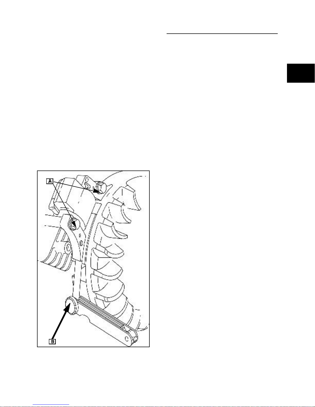
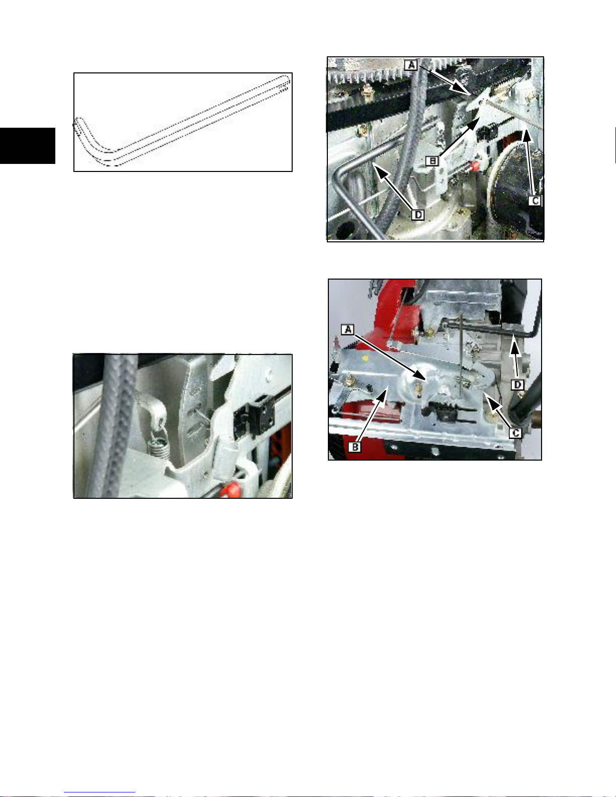
Static Governor Adjustment
(050000, 085400, 086400, 115400, 117400,
118400, 138400, 185400, 235400, 245400)
1. Loosen lock nut (A) holding governo r lever
(B) to governor crank ([C] Fig. 23).
2. Rotate thro ttle plate linkage from IDLE to
WOT(Wide Open T hrottle). Note direction
of rotation of the governor lever (B)
attached to the throttle linkage ([D]
Fig.23).
3. Place and hold the throttle plate linkage in
FAST position.
19
1
Static Gover nor Adjustment
(161400, 104700, 260700, 261700, 28Q700)
1. Loosen nut holding governor l ever ([A]
Fig. 25) to governor crank.
2. Rotate thr ottle linkage from idle to wide
open throttle. Note the direction of rotation
of the governor arm attached to the
throttle linkage.
3. Place and hold the throttle in high speed
position.
4. While holding the throttle plate, rotate the
governor shaft ([B] Fig. 25) until it stops in
the direction noted in step 2.
5. While holding the governor shaft, torque
the governor lever nut to listed value.
SEE SECTION 14- ENGINE SPECIFICATIONS.
Fig. 23
4. Rotate the governor shaft in direction
noted in previous step, until it stops.
5. While holding governor crank, torque the
governor lever nut (left hand
thread)(Fig.2.)
Fig. 25
Fig. 24
20
Fig. 26
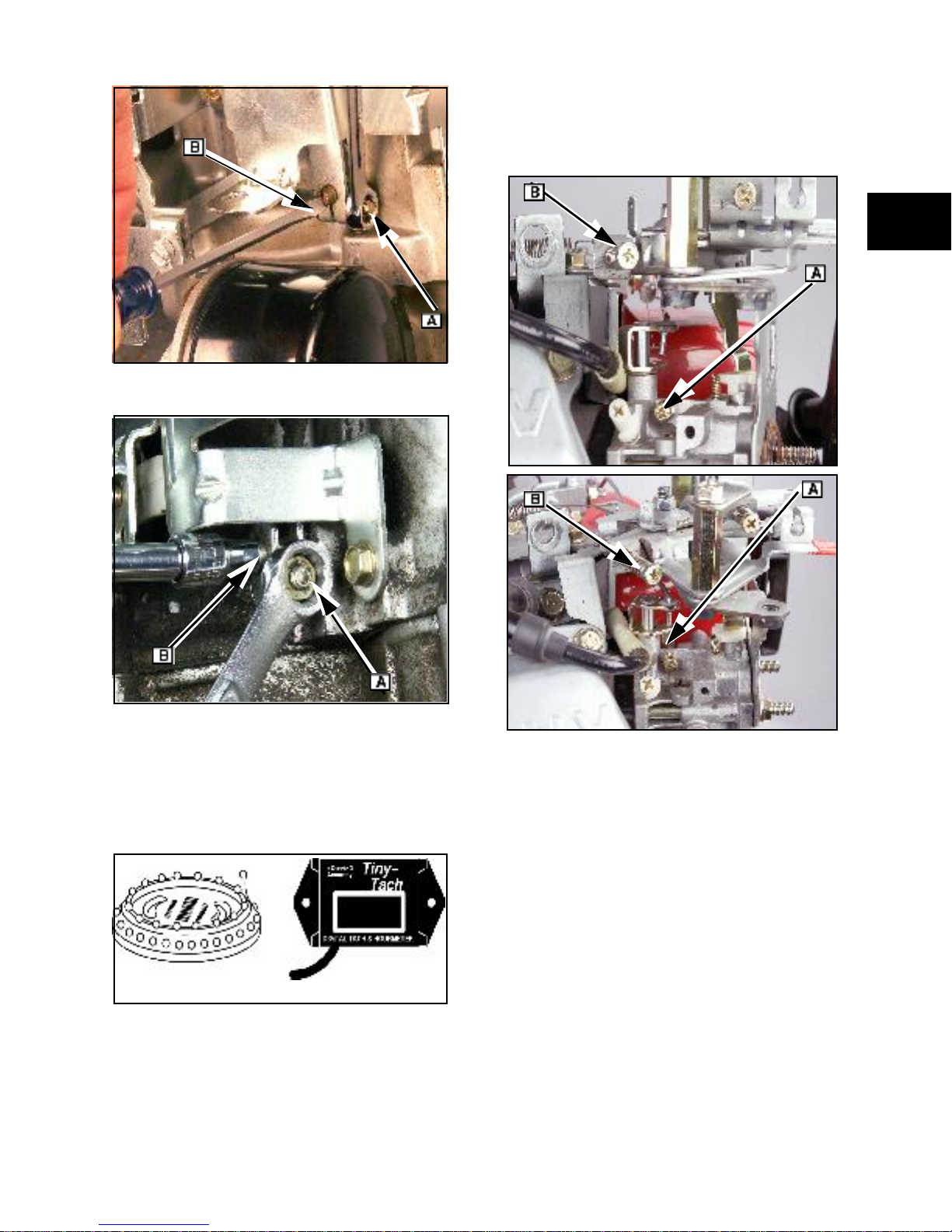
Fig. 27
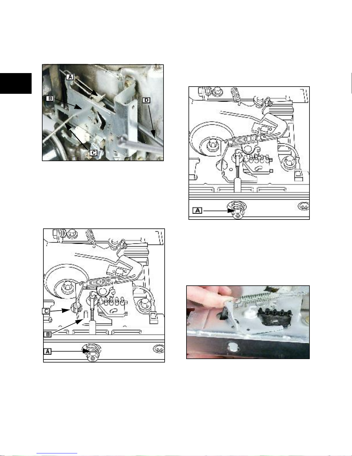
3. With the carburetor idl e speed screw (A),
adjust RPM to 1200 RPM.
4. With gover ned idle screw ([ B] Fig. 30),
adjust RPM to 1400 RPM.
1
Fig. 28
Governed Idle Spe ed Adjustments
(085400, 086400, 115400, 117400, 138400,
185400, 235400, 245400)
Recommended tools:
#19200 #19389
Fig. 29
1. Start and run engine at 1/2 throttle for 5
minutes to bring engine to operating
temperature.
2. Move throttle to SLOW.
Fig. 30
NOTE: (050000, 118400, 28Q700) Do not
have a Governed Idle Speed adjustment.
21
Go verned Idle RPM Adjustments
(161400, 260700, 261700)
5. Remove rod ([C] Fig. 33 through Fig. 35).
1
#19480 or #19229
Fig. 31
Install all linkages and sprin gs and be sure that
all carburetor adjustments have been made
before performing any of the running governor
adjustments. To find the correct top no load RPM
by model-type number, log into
thepowerportal. com//repower.
NOTE: (104700) Does not have a governed
idle adjustment.
Early production versio ns of 260700 and 261700
had governor levers with three spring anchor ing
slots. Position spring in middle slot.
Fig. 33
Fig. 32
Refer to figure that shows your model.
1. Start and run engine at 1/2 throttle for 5
minutes to bring engine to operating
temperature.
2. Move throttle to SLOW.
3. Align holes in the governor control lever
gear (A) and governor contro l plate ([B]
Fig. 33 through Fig. 35) Insert 0.125 in.
(3.2 mm) diameter rod (C).
4. Using tang bender tool (D), bend
governed idle speed tang to obtain 1400
RPM .
22
Fig. 34
Governed Idle RPM, Fixed Speed Adjustable
(161400 - No Generators)
1. Start and run engine at 1/2 throttle for 5
minutes to bring engine to operating
temperature.
2. Turn speed regulator nut (A)
counterclockwise (CCW) to align idle
speed holes (B) in governor control lever
gear with governor control plate.
3. Insert 0.12 5 in. (3.2 mm) diameter rod ([C]
Fig. 35).
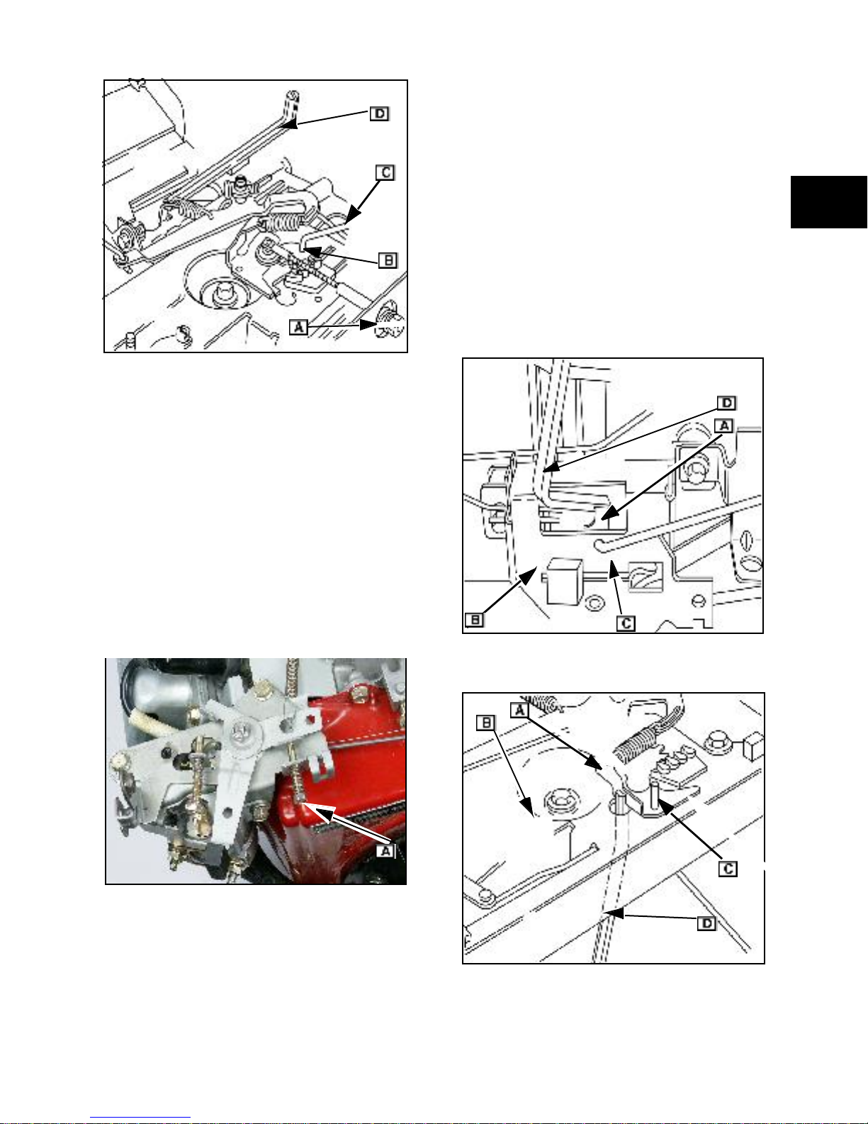
Fig. 35
4. Using tang bender tool ([D] Fig. 35), bend
governed idle spring tab to obtain 1400
RPM .
5. Remove rod.
• Some units may have remote throttles
furnished by the OEM.
1. Move throttle to FA ST .
2. Align holes in the governor control lever
gear (A) and governor contro l plate ([B]
Fig. 37 or Fig. 38).
3. Insert 0.12 5 in. (3.2 mm) diameter rod ([C]
Fig. 37 or Fig. 38).
NOTE: (104700) Alignment holes on early
productio n m odels were 0.062 in. (3.2 mm).
4. Using tang bender tool (D), bend spring
tab (or turn adjustment screw) to obtain
proper top no load RPM.
59
1
Top No Load RPM Adjus tments
(050000, 085400, 086400, 115400, 117400,
118400, 138400, 185400, 235400, 245400)
1. Start and run engine at 1/2 throttle for 5
minutes to bring engine to operating
temperature.
2. Move throttle to FA ST .
3. Adjust top no load limiting s crew ([ A] Fi g.
36) to obtain proper no load RPM.
Fig. 36
Fig. 37
Top No Load RPM Adjus tments
(104700, 161400, 260700, 261700, 28Q700)
• Refer to the figure that shows your
model.
Fig. 38
5. Remove rod.
23
1
Top No Load RPM, Fixed Speed
Adjustable
(161400 - No Generators)
Fig. 39
1. Turn speed regulator nut (A) clockwise
(CW) to align top no load holes in
governor control lever gear and governo r
control plate.
2. Insert 0.12 5 in. (3.2 mm) diameter rod ([B]
Fig. 40).
Top No Load RPM, Fixed Speed Adjustable
(161400 - Generators)
1. Turn the speed regulator nut ([A] Fig. 41)
until the desired top no load speed is
achieved.
Fig. 41
63
Fig. 40
3. Using tang bender tool ([C] Fig. 40), bend
governor spring tang to obtain proper top
no load R PM.
4. Remove rod.
Pre-Load RPM, Fixed Speed Adjustable
(161400 - Generators)
1. Push in and up on speed regulator nut to
disengage from notch in control panel.
2. Start and run engine at 1/2 throttle for 5
minutes to bring to operating temperature.
Fig. 42
3. Push the governor control all the way to
the end of its travel and hold it there.
4. While holding the governor control, (Fixed
Speed Regul ator rod removed for
24
clarity)use the tang bender ([A ] Fig. 42) to
obtain proper pre-load speed.
5. use the tang bender ([A] Fig. 42) to obtain
proper pre-loa d spee d.
6. As soon as pre-load RPM is set, move
throttle toIDLE.
7. Stop engine.
8. Engage speed regulator nut back into
notch in the control panel.
Top No Load RPM:
• 3150 RPM (50 cycles)
• 3750 RPM (60 cycles)
Pre Load RPM:
• 4000 RPM (50 cycles)
• 4300 RPM (60 cycles)
1
Fig. 43
Elec tro-Magnetic Idle Down
A djustments
NOTE: Governed idle speed and top no-load
speed must be properly set before adjusting the
electro-ma gneti c i dle down.
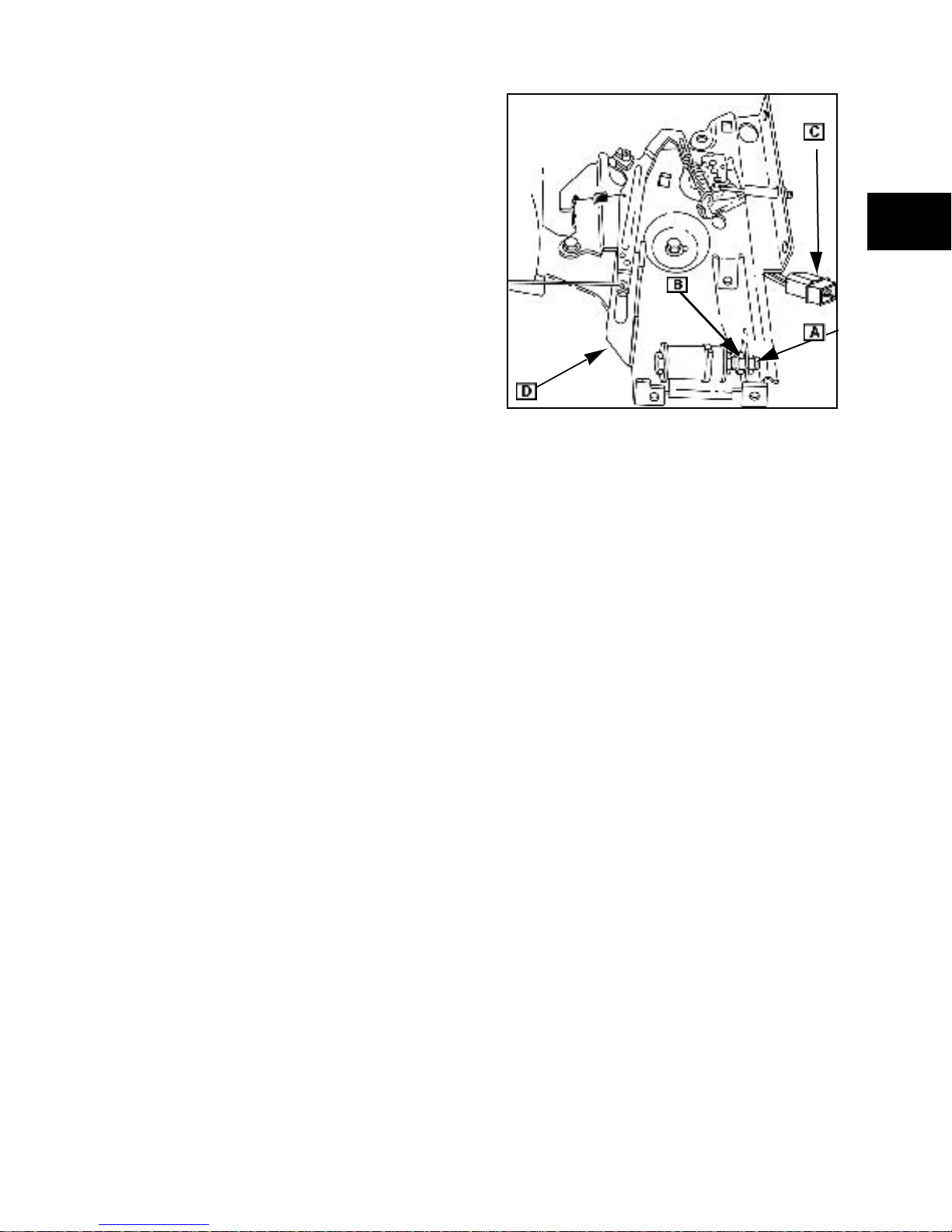
Electro-Magnetic Idle Down (161400)
1. Loosen both adjusting nuts ([A] and [B]
Fig. 43). Then, un screw nut (A) until flush
with end of bolt.
2. Start and run engine at 1/2 throttle for 5
minutes to bring engine up to operating
temperature.
3. With the engine running, apply 12VDC to
connect or (C). Extended governor lever
([D] Fig. 43) will be pulled against head of
idle bolt.
4. Adjust nut (A) to obtain 2300 RPM.
Remove 12VDC from connector.
5. Hold nut (A) and idle down control in
position. Tighten nut ([ B] Fig. 43.)
6. Reapply 12VDC to connector to check
electro-mag netic action and engine RPM.
Readjust as necessary.
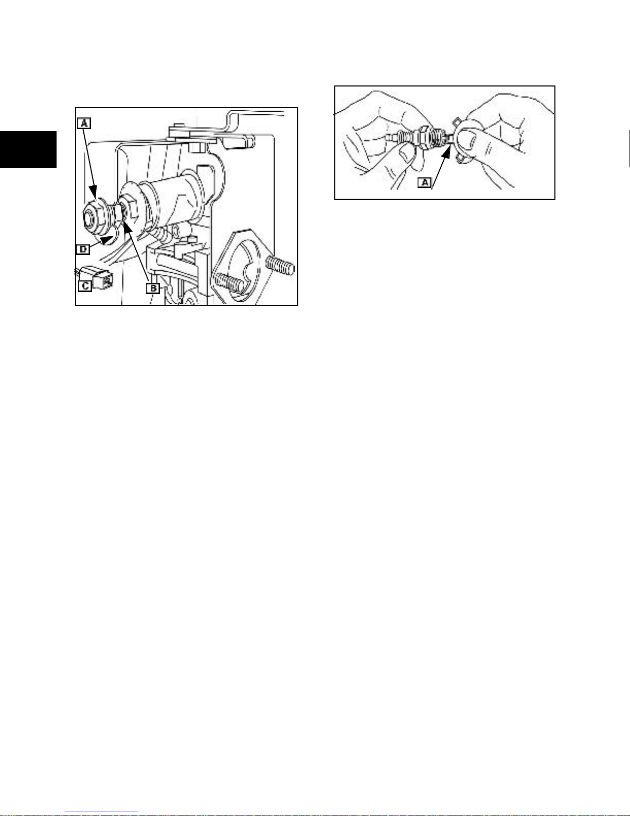
Elec tro-Magnetic Idle Down
(115400, 117400, 1184 00, 185400,
235400, 245400, 246400)
1. Loosen both adjusting nuts ([A] and [B]
Fig. 44). Then, un screw nut (A) until flush
with end of bolt.
2. Start and run engine at 1/2 throttle for 5
minutes to bring engine up to operating
temperature.
25
1
3. With the engine running, apply 12VDC to
white conn ector with the blue
wir es([ C]Fig. 44). Extended governor will
be pulled against head of idle down bolt.
([C]Fig. 44).
Use a wire gauge ([A] Fig. 45) to set the spark
plug gap.
Set spark plug gap at listed value.
Fig. 45
Torque spark plugs to li sted value.
SEE SECTION 14- ENGINE SPECIFICATIONS.
Valve Clea rance Adjustments
Fig. 44
4. Adjust nut ([A] Fig. 44) to obtain 2100-2500
RPM .
Use the lowest RPM in this range that the
electro -magne t will hold reliably. Remove 12 VDC
from connector.
5. Hold nut and idle down control in this
position and tighten nut ([B] Fig. 44) to
listed val ue.
SEE SECTION 14- ENGINE SPECIFICATIONS.
6. Re-apply 12VDC to connector to check
electro-mag netic action and engine RPM.
Re-adjust, if necessary.
Spar k Plug Maintenance
Replace Spark Plug
Replace spark plug every year. Replace spark
plugs if electrodes are burned away, or the
porcelain is cracked.
NOTE : Local laws may require the use of a
resistor spark plug to suppre ss ignition signals. If
an engine was originally equipped with a resistor
spark plug, replace it with the same type of spark
plug .
Adjust Valve Clearance
Valve clearances should al ways be adjusted on
a cold engine.
1. Remove the valve cover.
2. Rotate the crankshaft in the normal
direction until you get to TDC (Top Dead
Center) of the compression stroke.
3. Insert a narrow indicator (screwdriver or
small rod) into the spark plug hole against
the piston to indicate piston movement.
4. While watching the indicator, rotate
crankshaft clockwise (C W) past TDC until
piston is 0.25 in. (6mm) down from TDC.
This is to prevent the compression
release (if equipped) from affecting
adjustments.
5. Loosen the jamb nut on the rocker arm.
For correct clearance dimensions see page 255.
6. Insert the proper feeler gauge. While
moving it back and forth, carefully tighten
the adjustment screw u ntil a slight amount
of resistance is fe lt on the feeler gauge.
Do not blast-clean spark plugs. Spark plugs
should be cleaned by scraping or hand wire
brushin g and washing in a commercial solvent.
26
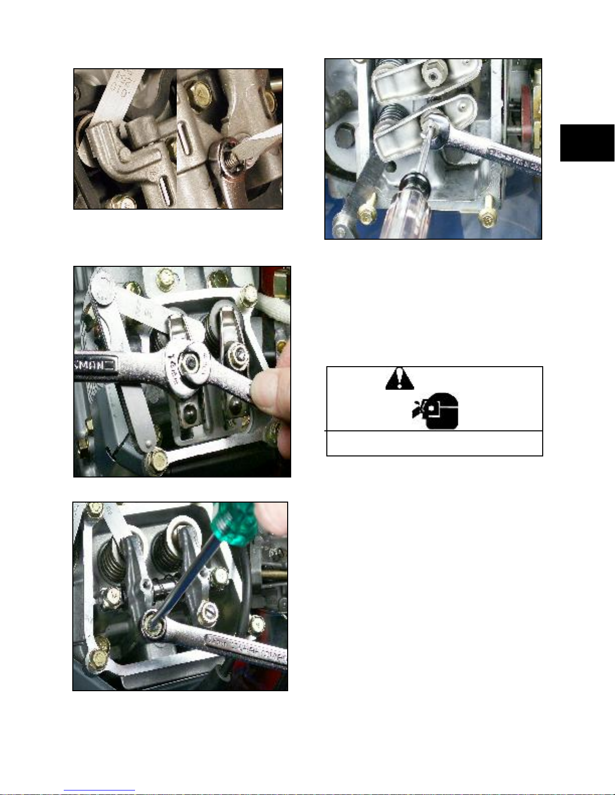
7. Tighten the jamb nut without moving the
adjus tment scr ew Fig. 46, 47, 49, 49.
Fig. 46
8. Rotate the crankshaft through a few
revolutions and recheck the clearance.
1
Fig. 49
Combus tion Cha mber De posits
Remove combust ion chamber deposits every
500 hours or whenever cylinder head is
removed.
Fig. 47
WARNING
Wear eye protection when using
compressed air to clean parts.
With the piston at Top Dead Center (TDC),
remove combustion chamber deposits from top
of piston with a plastic scr aper or a scotch pad.
CAUTION: Use care to prevent debris from
entering push rod or oil return cavities in cylinder.
Do not d amage cylinder, top of piston, cylinder
head and cylinder head gask et surfaces.
It is not necessary to remove the discoloration
marks on the piston, valves and/or cylinder head.
These marks are normal and will not affect
engine operatio n.
Remove the loose deposits from around t he top
ring land area using compressed air and a soft
bristle bru sh.
Fig. 48
27

1
28

SEC TION 2 - TROUBLESHOOTING
GENERAL INFORMATION............................................................................31
SYSTEMATIC ENGINE CHECKS.................................. ........... ..................... 31
IGNITION SYSTEM........................................................................................ 32
Spark Test................................................................................................................32
Spark Miss Test........................................................................................................32
CARBURETION ............................................................................................. 32
COMPRESSION ............................................................................................ 33
Compression Test....................................................................................................33
ELECTRICAL TEST EQUIPMENT............................. ....................................35
D igital Multimeters & Settings ........................................... .......................................35
AC Volts. ..................................................................................................................35
DC Volts...................................................................................................................35
D C Amps over 10 Amps...... ......................... ............................................................ 35
Ohms or Continuity ..................................................................................................35
Diode Test................................................................................................................36
AC Amps ..................................................................................................................36
D C Amps under 10 Amps ........................................................................................36
DC Shunt..................................................................................................................36
Tachometers............................................................................................................36
2
ALTERNATOR OUTPUT TESTS...................................................................36
DC Alternator............................................................................................................36
AC Alternator............................................................................................................38
1.2 Amp U nregulated Alternator................... ............................................................3 8
4 Amp Regulated Alte rnator ......................... ............................................................ 39
9 Amp Regulated Alte rnator ......................... ............................................................ 39
10 Amp Regulated Alternator. .................................................................................. 40
10 & 16 Amp Regulated Alte rnator .......................................................................... 41
Dual Circuit Alternator ..............................................................................................43
Tri–Circuit Alternator ................................................................................................44
29
 Loading...