

Briggs & Stratton 076000NG, 076000LP Service & Troubleshooting Manual
Home Generator System
Manual 278382GS Rev A 6/08
SERVICE & TROUBLESHOOTING MANUAL
HOME GENERATOR SYSTEM - 30kW
BRIGGS & STRATTON

FORWARD
This manual was written to assist authorized technicians and service personnel with the repair and
maintenance procedures for Briggs & Stratton home standby generator systems. It assumes that persons
using this manual have been properly trained in and are familiar with the servicing procedures for these
products, including the proper use of required tools and safety equipment and the application of
appropriate safety practices. Persons untrained or unfamiliar with these procedures or products should not
attempt to perform such work.
Proper maintenance and repair is important to safe, reliable operation of the standby system. The
troubleshooting, testing, maintenance, and repair procedures described in this manual are appropriate for
the models described herein. Alternative methods or procedures may pose risk to personal safety and the
safety and/or reliability of the equipment and are not endorsed or recommended by Briggs & Stratton.
All information, illustrations, and specifications contained in this manual were based on the data available
at the time of publication. Briggs & Stratton Corporation reserves the right to change, alter, or otherwise
improve the product or the product manuals at any time without prior notice.
Copyright © 2008 Briggs & Stratton Corporation
All rights reserved.
No part of this material may be reproduced or transmitted in any form or by any means, electronic or
mechanical, including photocopying or recording by any information storage and retrieval system, without
prior written permission from Briggs & Stratton Corporation.

TABLE OF CONTENTS
SECTION 1 - SAFETY, MAINTENANCE AND ADJUSTMENTS......................................1
SAFETY MESSAGES .................................................................................................................. 1
ACCESS TO THE GENERATOR................................................................................................. 5
GENERATOR COMPONENTS.................................................................................................... 6
GENERATOR CLEARANCES..................................................................................................... 9
SYSTEM CONNECTIONS........................................................................................................... 10
FUEL SUPPLY............................................................................................................................. 12
ENGINE MAINTENANCE ............................................................................................................ 13
SETTING THE EXERCISE TIMER.............................................................................................. 13
SECTION 2 - TROUBLESHOOTING.................................................................................17
SYSTEM CONTROL PANEL (SCP) ............................................................................................17
FAULT CODE INDICATIONS ...................................................................................................... 18
STOPPING THE SYSTEM FOR MAINTENANCE.......................................................................19
GENERATOR AC CONNECTION SYSTEM................................................................................ 20
(FAULT CODE_1) DEAD UNIT/LOW BATTERY VOLTAGE.......................................................21
(FAULT CODE_2) LOW OIL PRESSURE ................................................................................... 29
(FAULT CODE_3) LOW OUTPUT VOLTAGE............................................................................. 33
(FAULT CODE_4) ENGINE FAILS TO START/FAILS TO CRANK............... ................... ........... 39
(FAULT CODE_5) UNDER FREQUENCY................................................................................... 51
(FAULT CODE_6) OVER FREQUENCY ..................................................................................... 54
(FAULT CODE_7) HIGH TEMPERATURE.................................................................................. 55
(FAULT CODE_8) TRANSFER SWITCH FAILURE .................................................................... 58
Page i

SECTION 3- SPECIFICATIONS & REFERENCE.................................................. ............59
SPECIFICATIONS ............................................ ............................................ ................................ 59
SCHEMATIC ......................................... ....................................................................................... 60
WIRING DIAGRAM ...................................................................................................................... 61
Page ii
SECTION 1 - SAFETY, MAINTENANCE
AND ADJUSTMENTS
In The Interest Of Safety
This repair manual contains safety information
that is designed to:
• Make you aware of hazards associated
with engines.
• Inform you of the risk of injury associated
with those hazards.
• Tell you how to avoid or reduce the risk
of injury.
WARNING
Before attempting to service this equipment,
read and understand this manual and the
operating instructions of the equipment
Failure to follow instructions could result in
DEATH, SERIOUS INJURY (including
paralysis) or property damage.
The Safety Alert Symbol
The safety alert symbol ( ) is used to identify
safety information about hazards that can result
in personal injury.
A signal word (DANGER, WARNING, or CAUTION)
is used with the alert symbol to indicate the
likelihood and the potential severity of injury. In
addition, a hazard symbol may be used to
represent the type of hazard.
DANGER indicates a hazard which, if
not avoided, will result in death or
serious injury.
• Prior to work, read and understand the
section(s) of this manual that pertain to
the job. Follow all safety warnings.
• Wear suitable eye protection.
• When servicing engines or equipment,
prevent accidental starting by
disconnecting control panel fuse, spark
plug wire from the spark plug(s), and
disconnect negative battery cable.
• Disconnect all sources of supply voltage
before servicing the generator.
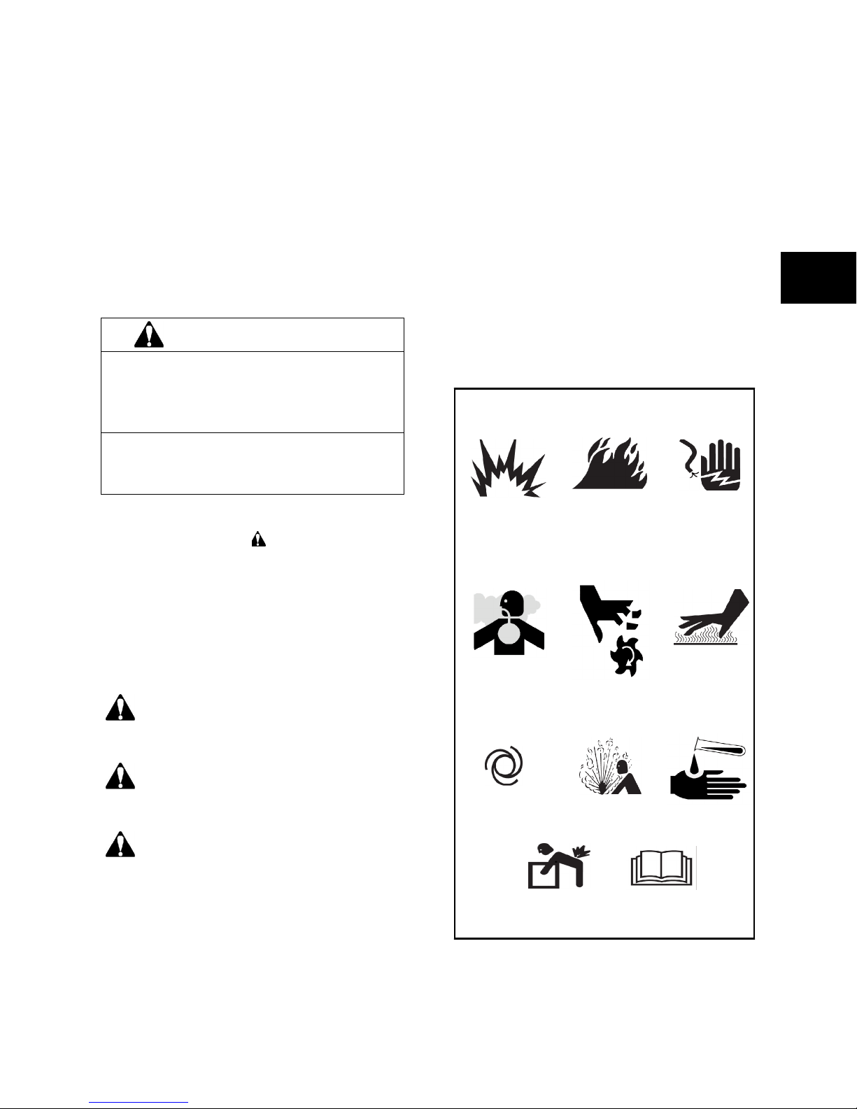
HAZARD SYMBOLS AND MEANINGS
Fire Electrical
Explosion
Toxic
Fumes
Rotating
Shock
Hot Surface
Parts
1
WARNING indicates a hazard which, if
not avoided, could result in death or
serious injury.
CAUTION indicates a hazard which, if
not avoided, might result in minor or
moderate injury.
CAUTION: When this signal word is used
without the alert symbol, it indicates a situation
that could result in damage to the engine.
Auto Start
Lift Hazard Read
Explosive
Pressure
Manual
Chemical
Burn
1
WARNING
WARNING
1
The engine exhaust from this product
contains chemicals known to the State of
California to cause cancer, birth defects, or
other reproductive harm.
WARNING
Storage batteries give off explosive
hydrogen gas during recharging.
Slightest spark will ignite hydrogen
and cause explosion.
Battery electrolyte fluid contains acid
and is extremely caustic.
Contact with battery contents will
cause severe chemical burns.
A battery presents a risk of electrical
shock and high short circuit current.
• DO NOT dispose of a battery in a fire.
• DO NOT allow any open flame, spark,
heat, or lit cigarette during and for several
minutes after charging a battery.
• DO NOT open or mutilate the battery.
• Wear protective goggles, rubber apron,
and rubber gloves.
• Remove watches, rings, or other metal
objects.
• Use tools with insulated handles.
WARNING
Running engine gives off carbon monoxide, and odorless, colorless,
poison gas.
Breathing carbon monoxide can
cause headache, fatigue, dizziness,
vomiting, confusion, seizures,
nausea, fainting, or death.
• Operate generator ONLY outdoors.
• Install a battery operated carbon monoxide alarm near the bedrooms.
• Keep exhaust gas from entering a confined area through windows, doors, ventilation intakes, or other openings.
Generator produces hazardous voltage.
Failure to properly ground generator
can result in electrocution.
Failure to isolate generator from
power utility can result in death or
injury to electric utility workers due to
backfeed of electrical energy.
• When using generator for backup power,
notify utility company.
• DO NOT touch bare wires or receptacles.
• DO NOT handle generator or electrical
cords while standing in water, while barefoot, or while hands or feet are wet.
• If you must work around a unit while it is
operating, stand on an insulated dry surface to reduce shock hazard.
• DO NOT allow unqualified persons or children to operate or service generator.
• In case of an accident caused by electrical shock, immediately shut down the
source of electrical power and contact the
local authorities. Avoid direct contact
with the victim.
• Despite the safe design of the home generator, operating this equipment imprudently, neglecting its maintenance, or
being careless can cause possible injury
or death.
• Remain alert at all times while working on
this equipment. Never work on the equipment when you are physically or mentally
fatigued.
• Before performing any maintenance on
the generator, disconnect the battery
cable indicated by a NEGATIVE, NEG, or
(-) first. When finished, reconnect that
cable last.
• After your home generator is installed, the
generator may crank and start without
warning any time there is a power failure.
To prevent possible injury, always set the
generator’s system switch to OFF AND
remove the 15 Amp fuse BEFORE working on the equipment.
2
WARNING
WARNING
Propane and Natural Gas are
extremely flammable and explosive.
Fire or explosion can cause severe
burns or death.
• Install the fuel supply system according to
N.F.P.A 37 and other applicable fuel-gas
codes.
• Before placing the home generator into
service, the fuel system lines must be
properly purged and leak tested.
• After the generator is installed, you should
inspect the fuel system periodically.
• NO leakage is permitted.
• DO NOT operate engine if the smell of
fuel is present or other explosive conditions exist.
• DO NOT smoke around the generator,
Wipe up any oil spills immediately. Ensure
that no combustible materials are left in
the generator compartment. Keep the
area near the generator clean and free of
debris.
Starter and other rotating parts can
entangle hands, hair, clothing, or
accessories.
• NEVER operate generator without protective housing or covers.
• DO NOT wear loose clothing, jewelry, or
anything that may be caught up in the
starter or other rotating parts.
• Tie up long hair and remove jewelry.
CAUTION
Installing the control panel’s 15A fuse
could cause the engine to start.
• DO NOT install this fuse until all plumbing
and wiring has been completed and
inspected.
CAUTION
1
WARNING
Contact with muffler area can result in
serious burns.
Exhaust heat/gases can ignite combustibles or structures, causing a fire.
• DO NOT touch hot parts and AVOID hot
exhaust gases.
• Allow equipment to cool before touching.
• DO NOT install the generator closer than
5 feet (1.5m) from any combustibles or
structures with combustible walls having a
fire resistance rating of less than 1 hour.
Excessively high operating speeds increase
risk of injury and damage to the generator.
Excessive load will cause engine shutdown.
• DO NOT tamper with governed speed.
Generator supplies correct rated frequency and voltage when running at governed speed.
• DO NOT modify the generator in any way.
CAUTION
Avoid prolonged or repeated skin contact with
used motor oil.
• Used motor oil has been shown to cause
skin cancer in certain laboratory animals.
• Thoroughly wash exposed areas with
soap and water.
3

1
CAUTION
Exceeding generators wattage/amperage
capacity can damage generator and/or electrical devices connected to it.
• See Essential Circuits in the Operator’s
manual.
• Start generator and let engine stabilize
before connecting electrical loads.
CAUTION
Improper treatment of generator can damage
it and shorten its life, or result in personal
injury.
• Use generator only for intended uses.
• If you have questions about intended use,
ask dealer or contact Briggs and Stratton.
• Operate generator only on level surface.
• Adequate, unobstructed flow of cooling
and ventilating air is critical to correct generator operation.
• The Coolant Fill, Battery, and Control
Panel doors must be installed whenever
the unit is running.
• DO NOT expose generator to excessive
moisture, dust, dirt, or corrosive vapors.
• Despite the safe design of the home generator, operating this equipment imprudently, neglecting its maintenance or
being careless can cause possible injury
or death.
• DO NOT start engine with air cleaner
removed.
• DO NOT insert any objects through the
cooling slots.
• DO NOT use the generator or any of its
parts as a step. Stepping on the unit can
cause stress and break parts. This may
result in dangerous operating conditions
from leaking exhaust gases, fuel leakage,
oil leakage, etc.
• If connected devices overheat, turn them
off and disconnect them from generator.
• Shut off generator if:
-electrical output is lost;
-equipment sparks, smokes, or emits
flames;
-unit vibrates excessively.
Standby Safety Practices
• This manual contains important safety
messages. Read these carefully and
understand them before proceeding with
maintenance and repairs.
• Become familiar with the Home
Generator System. Know its
applications, its limitations, and any
hazards involved.
• This unit must not be modified for any
application other than that for which it
was designed. If you have any questions
about the home generator System, ask
the dealer or consult Briggs and Stratton.
• Never handle any kind of electrical cord
or device while standing in the water,
while barefoot, or while hands and feet
are wet.
• Worn, bare, frayed, or otherwise
damaged electrical cord sets should not
be used with the Home Generator
System. Using a defective cord may
result is an electrical shock or damage to
the test equipment and/or the unit.
• The Home Generator System requires an
adequate supply of cooling air for
continued proper operation. Never allow
the free flow of cooling air into or out of
the unit to be obstructed in any way.
• Home Generator Systems produce
powerful voltages that can cause
extremely dangerous electrical shock.
Avoid contact with bare wires, terminals,
etc. Never permit an untrained person to
service or assist with the procedures
discussed in this manual.
• Never manually start or stop this unit with
electrical loads connected to the
receptacles and turned ON. Start the
engine and allow it to stabilize before
connecting any electrical loads. Turn
OFF and disconnect all electrical loads
before shutting down the generator.
• The manufacturer cannot anticipate
every circumstance that might involve or
constitute a hazard. Warnings in
manuals, warnings on hang tags, and
labels affixed to the unit are NOT allinclusive. Do not handle, operate, or
service the unit using a procedure or
method that is not specifically
recommended by the manufacturer.
4
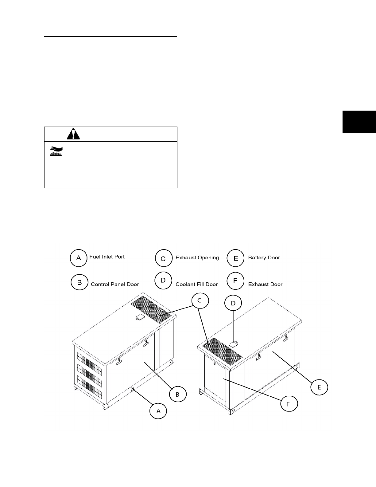
ACCESS TO THE GENERATOR
The home generator is equipped with an
enclosure that has four access doors (Figure 1).
The doors are named for a significant component
located behind them, as follows:
• Control Panel Door
• Coolant Fill Door
• Battery Door
• Exhaust Door
WARNING
Removing An Access Door
1. Insert key into lock of access door handle you
wish to open and turn one quarter turn
counterclockwise. Remove key. Handle will
remain unlocked until you relock it.
2. Grasp door’s handle and turn one quarter turn
counterclockwise to open.
3. Coolant Fill door is unlocked in the same
manner. It can be used for adding coolant or
engine oil.
NOTE: The enclosure also includes muffler and
radiator access panels, used for cleaning those
components. Those panels should remain closed
at all other times.
1
Contact with muffler area can result in
serious burns.
• DO NOT touch hot parts and AVOID hot
exhaust gases.
• Allow equipment to cool before touching.
Each Home Standby Generator System is
equipped with two identical keys. These keys fit
all the doors.
NOTE: The Coolant Fill, Battery and Control
Panel doors must be installed whenever the unit
is running, or the generator may overheat.
Installing An Access Door
1. Mount the door using the notches on the
generator base.
2. Close door and turn handle one quarter turn
clockwise.
3. Insert key into lock in handle and turn one
quarter turn clockwise. Remove key.
Figure1
5
1
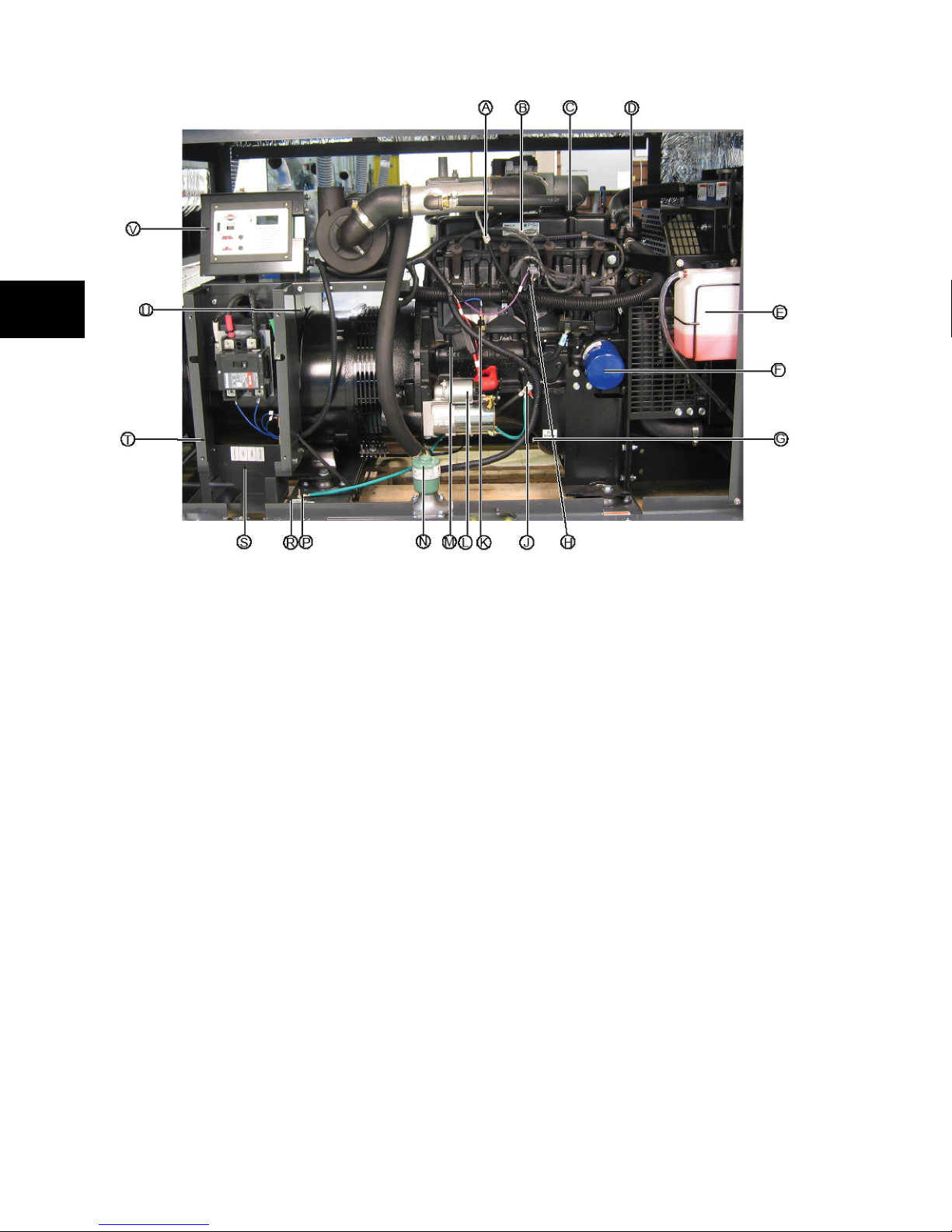
GENERATOR COMPONENTS
NOTE: Generator is shown with access door removed.
A - Oil Dip Stick - Used to check the engine oil
level.
B - Engine Label - Identifies engine model and
type.
C - Oil Fill Cap - Remove to service the engine
with recommended oil.
D - Thermostat - Allows the engine to heat up
quickly, and then to keep the engine at a constant temperature. It does this by regulating the
amount of coolant that goes through the radiator.
E - Coolant Recovery Bottle - Provides visual
indicator of engine coolant level.
F - Oil Filter - Filters engine oil to prolong system life.
G - Oil Drain Plug - Provided to facilitate oil
changing.
H - Ignition Coil - Amplifies the voltage of electricity supplied to the ignition system.
J - Battery Negative Cable - Cable connects
negative battery terminal to various electrical circuit and to the engine for starting.
K - Oil Pressure Switch - Monitors engine oil
pressure when the engine is running. Indicates a
drop to below the minimum permissible pressure.
L - Starter Contactor/Motor - The starter contactor supplies the high current
needed to run the starter motor and also provided the force needed to engage the starter.
The starter is an electric motor used to turn over
the engine to start it.
M - Battery Fuse Holder - Provides over-current
protection for safe operation of generator battery.
Fully insulated and water proof.
N - Fuel Solenoid - One inlet and one outlet,
electrically controlled to permit and shut off fluid
flow.
P - Generator Ground - Located on the frame
below the generator circuit breaker cover. If
required by local codes, should ONLY be used
for a ground rod. See System Control Panel for
other Ground locations.
R - Unit Data Decal - Identifies unit by model
and serial number.
S - Stub In Location - Located in bottom of circuit breaker enclosure for power cable stub in
location. Panel is removable to allow easy hole
cutting for conduit.
T - Circuit Breaker Enclosure - Equipped with
removable bottom to assist with conduit connection.
U - Automatic Voltage Regulator - Access hole
for voltage regulator adjustment.
V - Control Panel - Used for various tests, operation, and maintenance functions. See System
Control Panel on the next page.
6
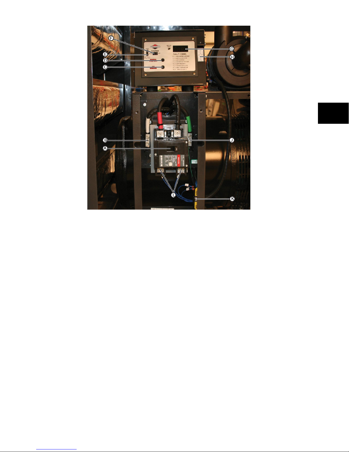
NOTE: Circuit breaker cover is removed for
illustration purposes.
A - Circuit Breaker — Protects the system from
shorts and other over-current conditions. Must be ON
to supply power to the Automatic Transfer Switch.
B - Generator Neutral Lug — Connection for neutral.
Neutral is not bonded to ground or generator.
C - Set Exercise Button — Used to set the exercise
cycle start time and day-of-the-week . Must be reset if
the fuse is removed or the battery is disconnected.
D- Manual Over-Ride Button — With the system
switch in AUTO position, push the manual over-ride
switch to start the generator. To turn off the generator,
push and hold the manual over-ride switch again until
engine stops.
E - 15 Amp Fuse — Protects the home generator DC
control circuits. If the fuse has ‘blown’ (melted open) or
was removed, the engine cannot crank or start.
F - System Switch — This two-position switch is the
most important control on the system and is used as
follows:
• “AUTO” position is the normal operating
position. If a utility power outage is sensed,
the system will start the generator. When
utility power is restored, AUTO lets the
engine stabilize internal temperatures, shuts
1
off the generator, and waits for the next
utility power outage.
• “OFF” position turns off running
generator, prevents unit from starting
and resets any detected faults.
G - Digital Display — Displays the total number of
hours the generator has been running and fault codes.
Used to schedule maintenance tasks and for
troubleshooting operational problems with the home
generator. All fault conditions are described in Fault
Description System.
H - Ten Pin Connection — Low Voltage connection
to signal fault contacts, transfer switch communication,
remote LED and auxiliary 12VDC power are made to a
removable ten-pin connector plug.
J - Generator Ground Lug — Located next to the
circuit breaker and should meet most codes,
standards, and regulations.
K - Utility Circuit Connection — Delivers power to
the generator’s circuit board (within internal battery
trickle charge) and water heater. When the power on
these leads is lost, the generator will start. Fuse
protected. Replace the fuse(s) only with identical
fuse(s).
L - Generator AC Lugs — Connection for generator
load(s).
7
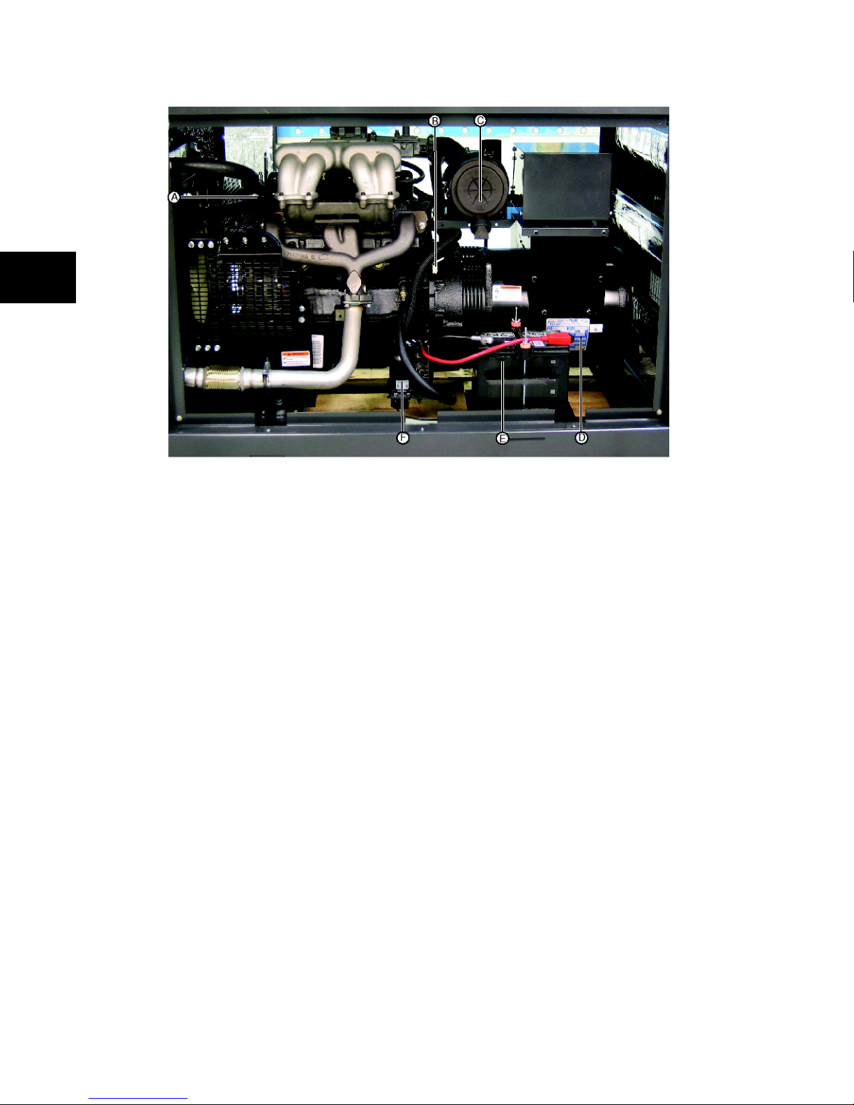
1
NOTE: Generator is shown with access door
removed.
A - Over Temperature Switch - Switch for automatically making or breaking an electrical circuit
at predetermined temperature. Will signal the
system control panel to shut down the generator
when the engine coolant reaches a critical level.
B - RPM Sensor - A permanent magnet built into
the sensor provides a magnetic field at the base
of the sensor. As each tooth of the flywheel
passes through the magnetic field, a signal (voltage pulse) is generated. The engine control unit
uses this to monitor engine speed to maintain a
specific generator frequency.
D - Alternator Data Plate - Lists alternator data
specific to the Marathon alternator assembly.
E - Battery - Stores and supplies electrical
energy. The manufacturer does not supply the
battery.
F- Engine Warmer - An electric heater that
heats the engine by keeping the engine coolant
warm to ease starting in cold weather. Connected to utility power and fully automatic.
C - Air Cleaner - Protects engine by filtering dust
and debris out of intake air.
8
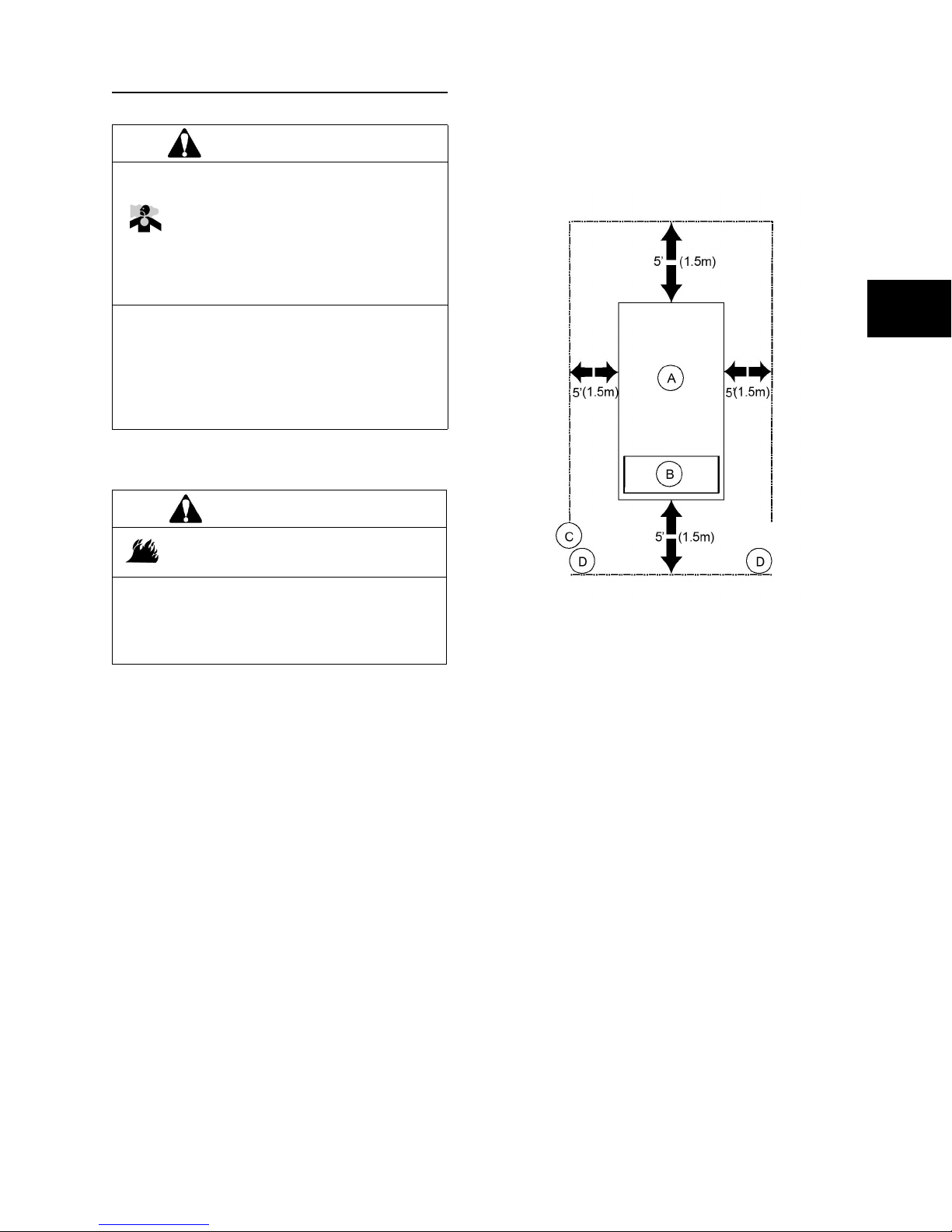
GENERATOR CLEARANCES
WARNING
Running engine gives off carbon monoxide, and odorless, colorless, poison gas.
Breathing carbon monoxide can
cause headache, fatigue, dizziness,
vomiting, confusion, seizures, nausea, fainting, or death.
drifting you may need to construct a
windbreak to protect the unit.
• Install the generator as close as possible
to the transfer switch and fuel supply to
reduce the length of wiring, conduit, and
piping.
• Operate generator ONLY outdoors.
• Install a battery operated carbon monoxide alarm near the bedrooms.
• Keep exhaust gas from entering a confined area through windows, doors, ventilation intakes, or other openings.
WARNING
Exhaust heat/gases can ignite combustibles or structures, causing a fire.
• DO NOT install the generator closer to 5
feet (1.5m) from any combustibles or
structures with combustible walls having a
fire resistance rating of less than 1 hour.
General Location Guidelines
• Install the unit outdoors ONLY.
• Place the unit on a prepared concrete
slab that is flat, level, and has provisions
for water drainage.
• Install the unit in a location where sump
pump discharge, rain gutter down
spouts, roof run-off, landscape irrigation,
or water sprinklers will not flood the unit
or spray the enclosure and enter any air
inlet or outlet openings.
• Install the unit where the location of any
services such as phone, electrical, fuel,
air conditioning, irrigation, including
covered, concealed and underground
services will not be affected or
obstructed.
• Install the unit where air inlet and outlet
openings will not become obstructed by
leaves, grass, snow, sand, etc. If
prevailing winds will cause blowing or
1
IMPORTANT: Laws or local codes may regulate
the distance to the fuel supply.
The Minimum clearances from aerial view of
generator (A) to combustible (C,D) materials is
shown in Figure 1.
• These distances are provided to give
generator location guidance relative
ONLY to combustibles, generator
cooling, and maintenance.
• The minimum distances in the figure are
as shown. All four sides of the generator
cannot be enclosed or restricted, even if
the minimum distances are maintained.
DO NOT connect (C) to (D).
• A roof cannot be constructed over the top
of the generator.
• Exhaust (B) is directed out the top of the
generator and must not be allowed to
accumulate.
9
1
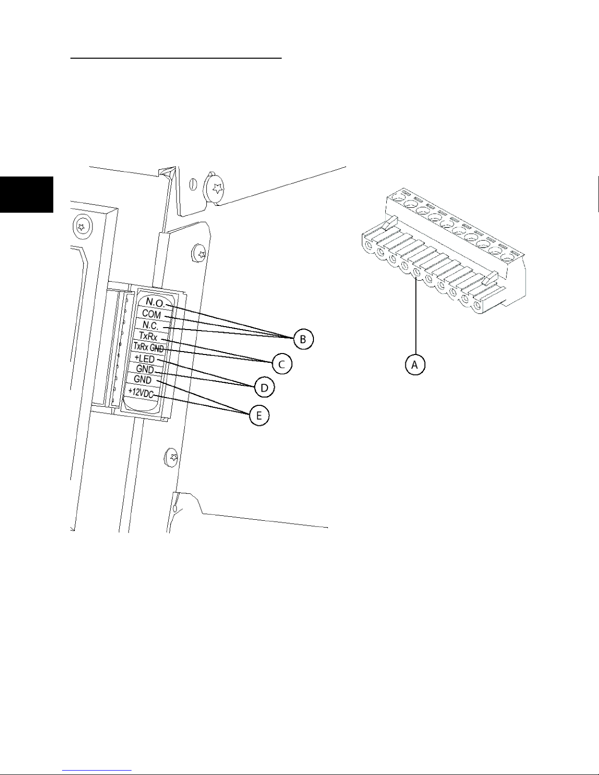
SYSTEM CONNECTION
Low Voltage (LV) connections to signal fault contacts, transfer switch communications, remote LED and
auxiliary 12VDC power are made to a removable ten-pin connector plug. Compare this illustration with the
location of these important connections:
A - 10 Pole Connector Plug
B - Fault Contacts — Use NO, COM and NC for operating a siren, light, optional GenAlert, etc. to alert
you in case of a fault. Contacts reverse state (NO goes to NC and vice versa) upon a fault condition.
C - Transfer Switch Communication — Connects to transfer switch control board for communication
interface.
D - Remote LED Output — Used to connect to the remote LED supplied with the generator. The remote
LED will turn on and off in a series of blinks if certain faults are detected in the generator.
E - +12Volt DC, .5 Amp Output — Internal auxiliary power supply.
10
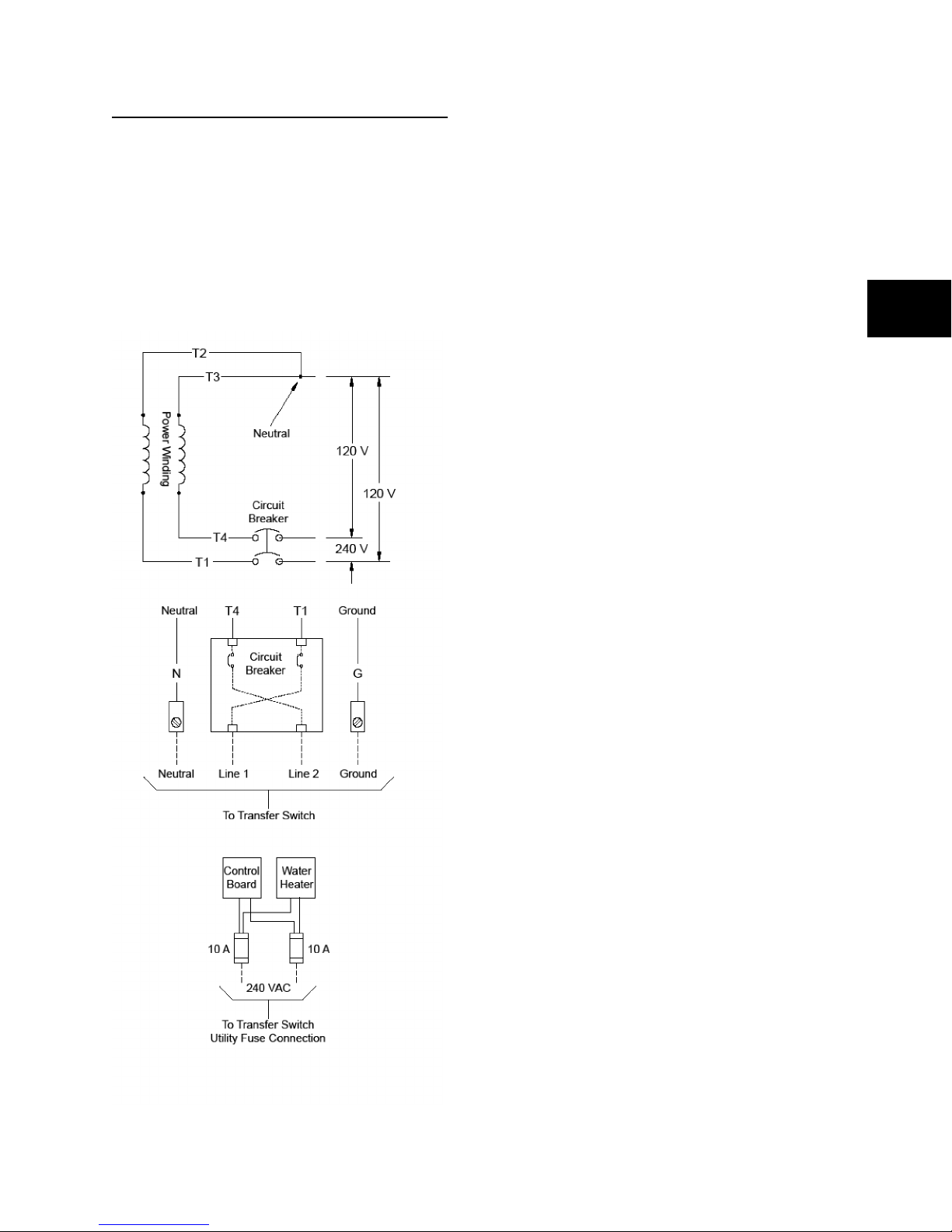
GENERATOR AC CONNECTION
SYSTEM
A single-phase, three-wire AC connection
system is used on the home generator. The
stator assembly consists of a pair of stationary
windings with two leads brought out of each
winding. The junction of leads T2 and T3 forms
the neutral lead, as shown schematically and as
wiring diagram below. A complete schematic and
wiring diagram can be found later in this manual.
NOTE: Neutral is not bonded to ground at
generator.
Grounding the Generator
Ground the home generator per applicable
codes, standards and regulations. There are two
generator Ground lug locations. The one inside
the alternator junction box next to the circuit
breaker is the primary lug and should meet most
applications. The second Ground lug is located
on the frame below the generator circuit breaker
cover, and should ONLY be used for a ground
rod located at the generator, if required by local
codes. See Controls for location.
Utility Circuit Connection
“240V Utility” leads must be routed in conduit.
The “240V Utility” leads deliver power to the
generator’s circuit board and water heater. This
power also charges the battery. When power on
these leads is lost, the generator will start.
Fault Detection System
The generator may have to run for long periods
of time with no operator present. For that reason,
the system is equipped with sensors that
automatically shut down the generator in the
event of potentially damaging conditions, such
as low oil pressure, high water temperature, over
speed, and other conditions. Refer to Fault
Detection System for more detailed information.
1
11
1
FUEL SUPPLY
Depending on the generator model number, the
home standby generator was manufactured and
shipped to run on natural gas or liquid propane
vapor. No matter which type of fuel the generator
was manufactured to run on, it can be field
converted to operate on either type of fuel. When
troubleshooting, engine performance is
dependent on receiving the specific pressure
and volume of fuel under varying load conditions
with all gas appliances turned on and operating.
For fuel consumption and pressure
specifications, consult the installation manual.
For proper engine function, factors that are
inherent to each of these fuels, your location and
the duration of possible utility interruptions are
important considerations in the following fuel
guidelines:
• Use clean, dry fuel, free of moisture or
any particulate material. Using fuels
outside the following recommended
values may cause performance
problems.
• For engines set up to run on propane
vapor (LP), commercial grade HD5
propane with a minimum fuel energy of
2500 BTUs/ft3 with maximum propylene
content of 5% and butane and heavier
gas content of 2.5% and minimum
propane content of 90%.
10F (5.6C) above 77F (25C). These factors must
be considered when determining total generator
load.
WARNING
Propane and Natural Gas are
extremely flammable and explosive.
Fire or explosion can cause severe
burns or death.
• Install the fuel supply system according to
N.F.P.A 37 and other applicable fuel-gas
codes.
• Before placing the home generator into
service, the fuel system lines must be
properly purged and leak tested.
• After the generator is installed, you should
inspect the fuel system periodically.
• NO leakage is permitted.
• DO NOT operate engine if the smell of
fuel is present or other explosive conditions exist.
• DO NOT smoke around the generator,
Wipe up any oil spills immediately. Ensure
that no combustible materials are left in
the generator compartment. Keep the
area near the generator clean and free of
debris.
WARNING
Propane and Natural Gas are
extremely flammable and explosive.
Fire or explosion can cause severe
burns or death.
• The home generator is equipped with an
automatic safety gas “fuel shut-off” valve.
• DO NOT operate the equipment if the “fuel
shut-off” valve is missing or inoperative.
Power Decrease at High Altitude or High
Temperature
Air density is less at high altitudes, resulting in
less available engine power. Specifically, engine
power will decrease 3.5% for each 1,000 feet
(300 meters) above sea level and 1% for each
12
SETTING THE EXERCISE TIMER
The home generator is equipped with an
exercise timer that will start and exercise the
system once every seven days. During this
exercise period, the unit runs for approximately
20 minutes and then shuts down. Electrical load
transfer DOES NOT occur during the exercise
cycle (unless an utility power outage occurs).
A button on the control panel is labeled “Set
Exercise” (see System Control Panel). The
specific day and the specific time of day this
button is pressed is programmed into the control
board memory. This date and time is then used
to automatically initiate the system exercise
cycle. The “Set Exercise” legend on the control
panel will flash until the set exercise cycle is set.
To perform the Set Exercise procedure:
1. Choose the day and time you want your home
generator to exercise.
2. On that day and time, press and hold down the
“Set Exercise” button for three seconds.
NOTE: “SET EXERCISE” will flash until the
button is pressed for three seconds, then “SET
EXERCISE” will illuminate for 5 seconds, and
finally turn off.
3. The unit will then start and run it’s 20 minute
exercise cycle.
For example, if you press the “Set Exercise”
button on Sunday morning at 10:00 AM, the unit
will run an immediate exercise cycle and an
exercise cycle will occur every following Sunday
at 10:100 AM (+/- 1/2 hour).
NOTE: “Set Exercise” will only work if the unit is
in the Automatic mode and this exact procedure
is followed. The exerciser will need to be re-set
whenever the 15 Amp fuse is removed or
changed, or if the 12 Volt DC battery is
disconnected.
If you want to change the day and time the unit
exercises, simply perform the “Set Exercise”
procedure at the exact weekday and time you
want it to take place.
GENERATOR MAINTENANCE
Generator maintenance consists of keeping the
unit clean. Operate the unit in an environment
where it will not be exposed to excessive dust,
dirt, moisture or any corrosive vapors. Cooling air
louvers on the enclosure must not become
clogged with snow, leaves, or any other foreign
material.
Check the cleanliness of the unit frequently and
clean when dust, dirt, oil, moisture or other
foreign substances are visible on its exterior/
interior surface.
NOTE: DO NOT use direct spray from a garden
hose to clean generator. Water can enter the
engine and generator and cause problems.
Engine Maintenance
An engine manual was packaged with this
system. Please refer to it for all engine-related
maintenance topics. However, proper engine
cooling and lubrication are so important we also
reference them.
Engine Oil
The system is filled with the recommended nonsynthetic oil (API SL 10W-30W). This allows for
proper system operation in a wide range of
temperature and climate conditions.
NOTE: Refer to the engine operator’s manual for
the recommended oil change intervals.
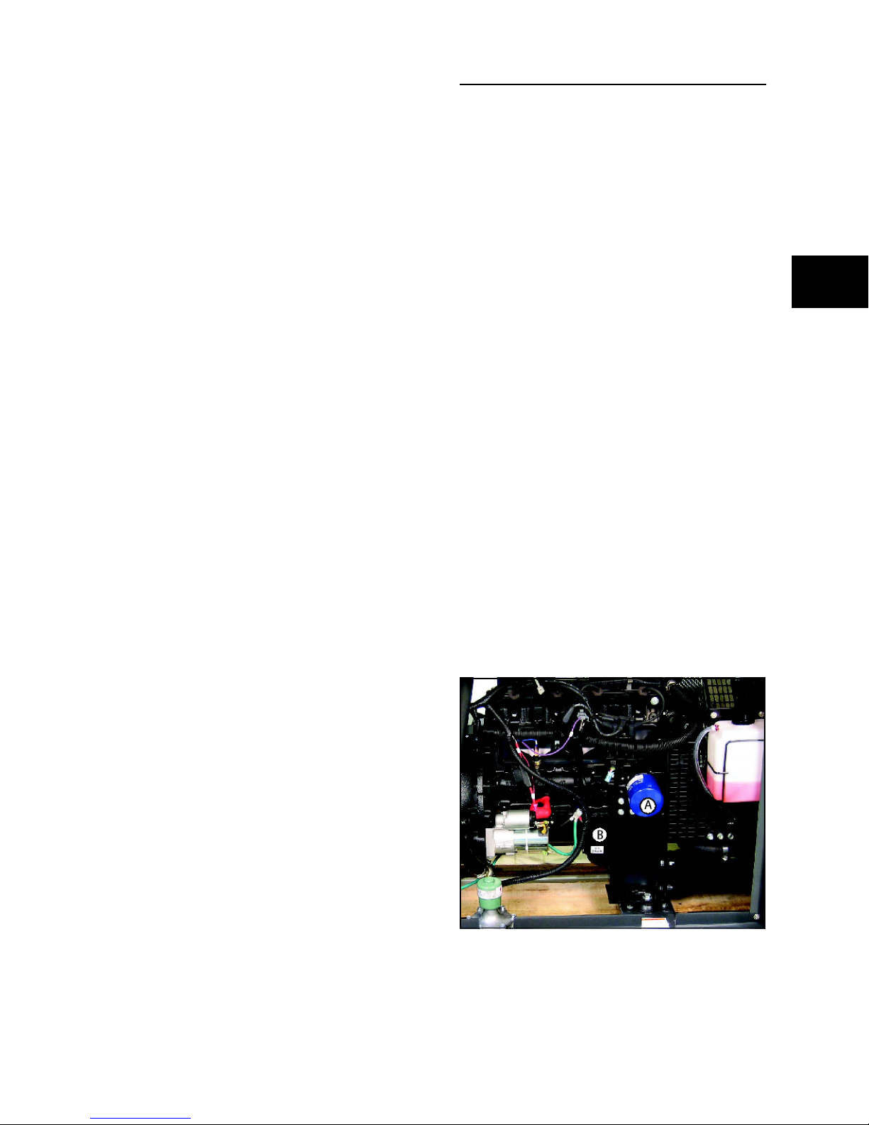
Shown here is the oil drain location (B) and the
oil filter (A).
1
13
Figure2
Changing Engine Oil
CAUTION
Avoid prolonged or repeated skin contact with
used motor oil.
Engine Coolant System
With the engine cold, check the coolant level in
the coolant recovery bottle, seen inside the
Control Panel door. Maintenance instructions for
engine coolant are found in the engine operator’s
manual.
1
• Used motor oil has been shown to cause
skin cancer in certain laboratory animals.
• Thoroughly wash exposed areas with
soap and water.
KEEP OUT OF THE REACH OF CHILDREN.
DON’T POLLUTE. CONSERVE RESOURCES.
RETURN USED OIL TO COLLECTION
CENTERS.
1. Put SYSTEM switch in OFF. Remove 15 Amp
fuse. Disconnect negative battery cable from
negative battery terminal.
2. Change oil while the engine is still warm from
running, as described in the engine operator’s
manual.
NOTICE
Any attempt to crank or start the engine before
it has been properly serviced with the recommended coolant or oil will result in equipment
failure.
BATTERY
Charging the Battery
If it is necessary to charge the battery, proceed
as follows:
1. Set generator’s system switch to OFF.
2. Remove 15 Amp fuse from control panel.
3. Disconnect negative battery cable to negative
battery terminal (indicated by NEGATIVE,
NEG, or (-)).
NOTICE
Failure to disconnect the negative battery
cable will result in equipment failure.
• DO NOT attempt to jump start the battery.
• Damage to equipment resulting from failure to follow this instruction will void warranty.
• Refer to Maintenance in the Operator’s
Manual and engine manual for coolant
and oil fill information.
• Damage to equipment resulting from failure to follow this instruction will void
engine and generator warranty.
To fill your engine with oil:
Follow the oil grade recommendation and oil fill
instructions given in the engine operator’s
manual.
To make the task of adding oil more convenient,
we recommend the use of a funnel attached to
the length of tubing long enough to reach from
the Coolant Fill door to the oil fill opening on the
engine valve cover. Recheck oil level,reconnect
battery, install fuse, put in AUTO and reset
exercise timer when complete.
14
4. Charge battery with a battery charger at 2
Amps until battery holds 12 Volts.
NOTE: With the battery installed and utility
power available to the transfer switch, the battery
receives a trickle charge whenever the engine is
not running. It may take up to 72 hours to fully
charge a discharged battery with the trickle
charge. The trickle charge is not able to recharge
a battery that is completely discharged.

WARNING
Storage batteries give off explosive
hydrogen gas during recharging.
Slightest spark will ignite hydrogen
and cause explosion.
Battery electrolyte fluid contains acid
and is extremely caustic.
Contact with battery contents will
cause severe chemical burns.
A battery presents a risk of electrical
shock and high short circuit current.
• DO NOT dispose of battery in fire.
• DO NOT allow any open flame, spark,
heat, or lit cigarette during and for several
minutes after charging a battery.
• DO NOT open or mutilate the battery.
• Wear protective goggles, rubber apron,
and rubber gloves.
• Remove watches, rings, or other metal
objects.
• Use tools with insulated handles.
Servicing the Battery
If it is necessary to service the battery, proceed
as follows:
1. Set control board System switch to OFF.
2. Remove 15 Amp fuse from control panel.
3. Service or replace battery as required.
4. Connect red battery cable to battery positive
terminal (indicated by POSITIVE, POS, or (+)).
5. Connect negative battery cable to negative
battery terminal (indicated by NEGATIVE,
NEG, or (-)).
6. Ensure hardware on both positive and
negative battery terminals is secure.
7. Reinstall 15 Amp fuse in control panel.
8. Set generator’s system switch to AUTO.
9. Reset exercise timer. See Setting Exercise
Timer.
To Clean the Generator
NOTICE
Improper treatment of generator can damage
it and shorten its life.
1
5. Connect negative battery cable to negative
battery terminal (indicated by NEGATIVE,
NEG, or (-)).
6. Ensure hardware on both positive and
negative battery terminals is secure.
7. Reinstall 15 Amp fuse in control panel.
CAUTION
Installing the control panel’s 15A fuse
could cause the engine to start.
• DO NOT install this fuse until all plumbing
and wiring has been completed and
inspected.
8. Set generator’s system switch to AUTO.
9. Reset exercise timer. See Setting Exercise
Timer.
• DO NOT expose generator to excessive
moisture, dust, dirt, or corrosive vapors.
• DO NOT insert any objects through cooling slots.
• Use a damp cloth to wipe exterior
surfaces clean.
• Use a soft bristle brush to loosen caked
on dirt, oil, etc.
• Use a vacuum cleaner to pick up loose
dirt and debris.
• Use low pressure air (not to exceed 25
psi) to blow away dirt. Inspect cooling air
slots and openings on the generator.
These openings must be kept clean and
unobstructed.
15

1
16
 Loading...