

Briggs & Stratton 040298, 040298A, 040301, 040315, 040320 Service & Troubleshooting Manual
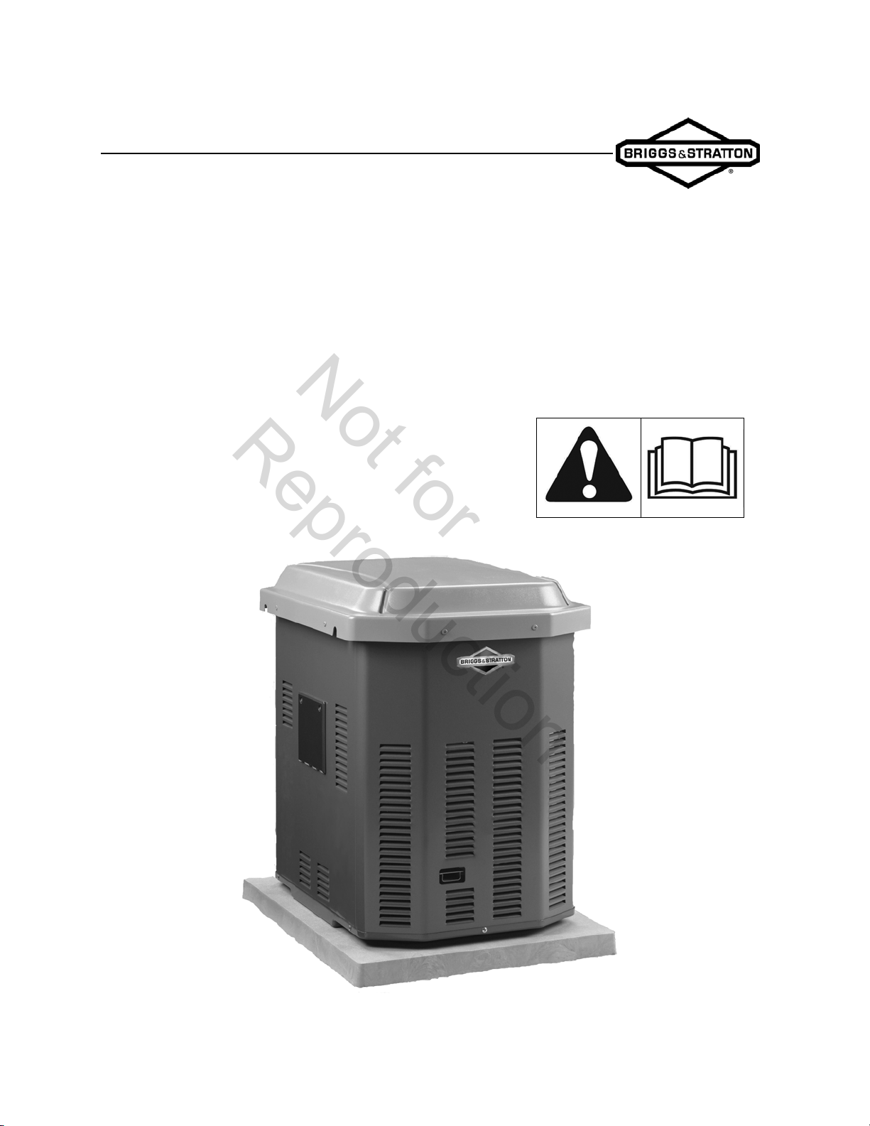
Home Generator System
Not for
Reproduction
Manual 278994GS Rev. -
SERVICE & TROUBLESHOOTING MANUAL
BRIGGS & STRATTON
HOME GENERATOR SYSTEM - 7kW

FORWARD
Not for
Reproduction
This manual was written to assist technicians and service personnel with the repair and maintenance procedures for
Briggs & Stratton Home Standby Generators. It assumes that persons using this manual have been properly trained in
and are familiar with the servicing procedures for these products, including the proper use of required tools and safety
equipment and the application of appropriate safety practices. Persons untrained or unfamiliar with these procedures or
products should not attempt to perform such work.
Proper maintenance and repair is important to safe, reliable operation of all engines and engine-driven systems. The
troubleshooting, testing, maintenance, and repair procedures described in this manual are appropriate for the Briggs &
Stratton Home Standby Generators described herein. Alternative methods or procedures may pose risk to personal
safety and the safety and/or reliability of the engine and are not endorsed or recommended by Briggs & Stratton.
All information, illustrations, and specifications contained in this manual were based on the data available at the time of
publication. Briggs & Stratton Corporation reserves the right to change, alter, or otherwise improve the product or the
product manuals at any time without prior notice.
Copyright © 2010 Briggs & Stratton Corporation
All rights reserved.
No part of this manual may be reproduced or transmitted in any form or by any means, electronic or mechanical,
including photocopying or recording by any information storage and retrieval system, without prior written permission
from Briggs & Stratton Corporation.
This generator is rated in accordance with UL (Underwriters Laboratories) 2200 (stationary generator assemblies) and
CSA (Canadian Standards Association) standard C22.2 No. 100-04 (motors and generators).

SECTION 1 - Safety, Maintenance and Adjustments
Not for
Reproduction
SECTION 2 - Troubleshooting
SECTION 3 - Unit Disassembly
SECTION 4 - Generator Specifications
1
2
3
4

THISPROPER SERVICE AND REPAIR IS IMPORTANT
Not for
Reproduction
TO THE SAFE, ECONOMICAL AND RELIABLE
MODELS COVERED IN THIS MANUAL
• 040298
• 040298A
• 040301
• 040315
• 040320
SECTION 1 - SAFETY, MAINTENANCE AND ADJUSTMENTS
Not for
Reproduction
Equipment Description
This product is intended for use as an optional residential
generator system which provides an alternate source of
electric power. This product does not qualify for emergency
standby as defined by NFPA 70 (NEC).
Every effort has been made to ensure that the information in
this manual is accurate and current. However, we reserve the
right to change, alter, or otherwise improve the product and
this document at any time without prior notice.
This repair manual contains safety information that is
designed to:
• Make you aware of hazards associated with
generators.
• Inform you of the risk of injury associated with
those hazards.
• Tell you how to avoid or reduce the risk of injury.
Signal Words in Safety Messages
WARNING Before attempting to service this
equipment, read and understand this manual and the
operating instructions of the generator. Failure to follow
instructions could result in property damage, serious
injury (including paralysis) or even death.
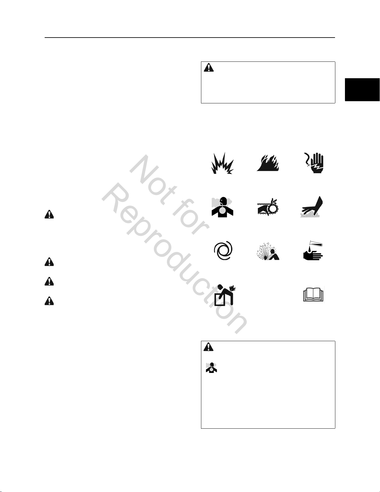
Safety Symbols and Meanings
EXPLOSION FIRE ELECTRICAL
SHOCK
1
1
The safety alert symbol is used to identify safety
information about hazards that can result in personal injury.
A signal word (DANGER, WARNING, or CAUTION) is used
with the alert symbol to indicate the likelihood and the
potential severity of injury. In addition, a hazard symbol may
be used to represent the type of hazard.
DANGER indicates a hazard which, if not avoided, will
result in death or serious injury.
WARNING indicates a hazard, which, if not avoided,
could result in death or serious injury.
CAUTION indicates a hazard which, if not avoided, could
result in minor or moderate injury.
NOTICE address practices not related to personal injury.
TOXIC FUMES ROTATING
PARTS
AUTO START EXPLOSIVE
PRESSURE
LIFT HAZARD READ MANUAL
WARNING Running engines gives off carbon
monoxide, an odorless, colorless, poison gas.
Breathing carbon monoxide can cause headache,
fatigue, dizziness, vomiting, confusion, seizures,
nausea, fainting, or death.
• Operate generator ONLY outdoors.
• Install a battery operated carbon monoxide alarm
near the bedroom.
• Keep exhaust gas from entering a confined area
through windows, doors, ventilation intakes, or
other openings.
HOT SURFACE
CHEMICAL
BURN
1
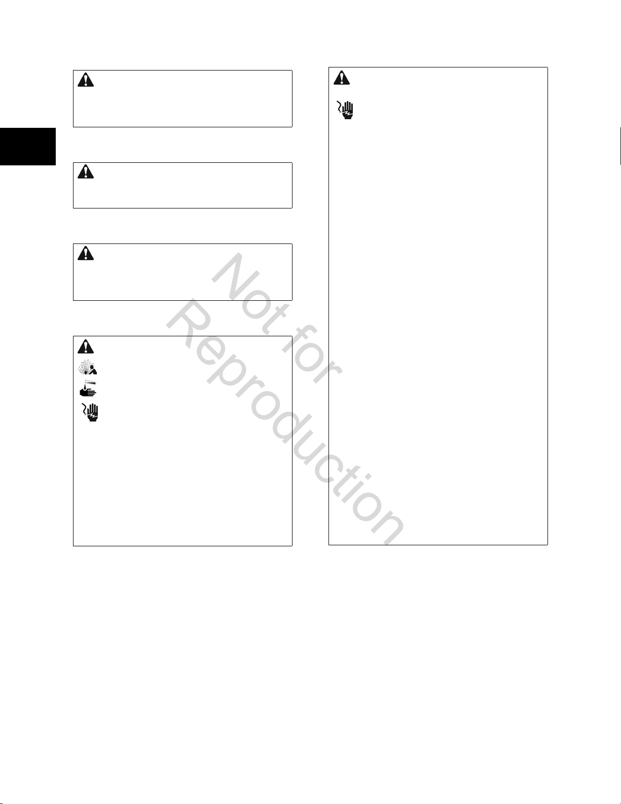
WARNING Battery posts, terminals, and related
Not for
Reproduction
accessories contain lead and lead compounds, chemicals
known to the State of California to cause cancer and
reproductive harm. Wash hands after handling.
1
WARNING The engine exhaust from this product
contains chemicals known to the State of California to
cause cancer, birth defects, or other reproductive harm.
1
WARNING Certain components in this product and
related accessories contain chemicals known to the State
of California to cause cancer, birth defects, or other
reproductive harm. Wash hands after handling.
WARNING Storage batteries give off explosive
hydrogen gas during recharging. Slightest spark
will ignite hydrogen and cause explosion. Battery
electrolyte fluid contains acid and is extremely
caustic. Contact with battery contents will cause
severe chemical burns. A battery presents a risk
of electrical shock and high short circuit current.
• DO NOT dispose of a battery in a fire. Recycle the
battery.
• DO NOT allow any open flame, spark, heat, or lit
cigarette during and for several minutes after
charging a battery.
• DO NOT open or mutilate the battery.
• Wear protective gloves, rubber apron, rubber boots,
and rubber gloves.
• Remove watches, rings, or other metal objects.
• Use tools having insulated handles.
WARNING Generators produce hazardous voltage.
Failure to properly ground generator can result in
electrocution. Failure to isolate generator from
utility power can result in death or injury to
electric utility workers due to back feed of
electrical energy.
• When using generator for backup power, notify
utility.
• DO NOT touch bare wires or bare receptacles.
• DO NOT use generator with electrical cords which
are worn, frayed, bare, or otherwise damaged.
• DO NOT handle generator or electrical cords while
standing in water, while barefoot, or while hands and
feet are wet.
• If you must work around a unit while it is operating,
stand on an insulated dry surface to reduce the risk
of a shock hazard.
• DO NOT allow unqualified persons or children to
operate or service generator.
• In case of accident caused by electrical shock,
immediately shut down the source of electrical
power and contact the local authorities. Avoid direct
contact with the victim.
• Despite the safe design of the residential generator,
operating the equipment imprudently, neglecting its
maintenance, or being careless can cause possible
injury or death.
• Remain alert at all times while working on this
equipment. Never work on the equipment when you
are physically or mentally fatigued.
• Before performing any maintenance on the
generator, disconnect the battery cable indicated by
a NEGATIVE, NEG or (-) first. When finished,
reconnect that cable last.
• After the system is installed, the generator may
crank and start without warning any time there is a
power failure. To prevent possible injury, always set
the generator’s system switch to OFF, remove the
service disconnect from the disconnect box, AND
remove the 15 Amp fuse BEFORE working on the
equipment.
2
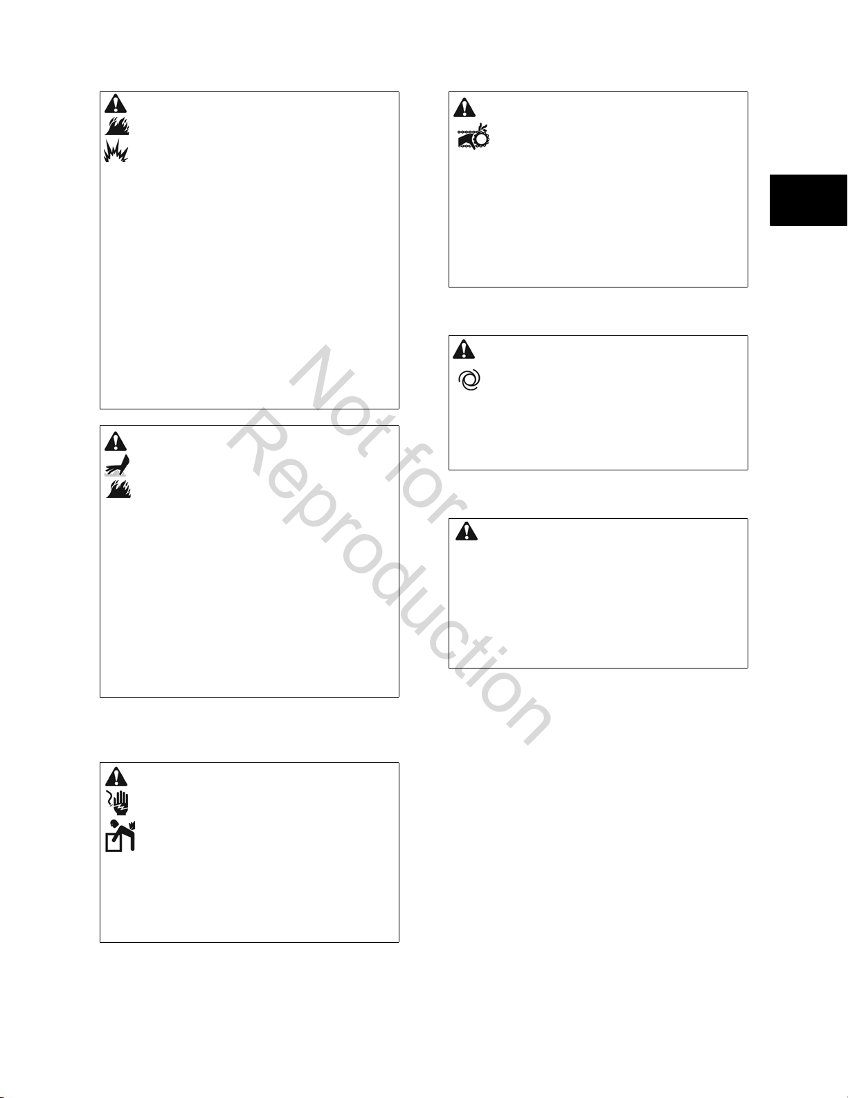
WARNING Propane and Natural Gas are extremely
Not for
Reproduction
flammable and explosive. Fire or explosion can
cause severe burns or death.
• Install the fuel supply system according to NFPA 37
and other applicable fuel-gas codes.
• Before placing the generator into service, the fuel
system lines must be properly purged and leak
tested.
• After the generator is installed, you should inspect
the fuel system periodically.
• NO leakage is permitted.
• DO NOT operate engine if smell of fuel is present or
other explosive conditions exist.
• DO NOT smoke around the generator. Wipe up any
oil spills immediately. Ensure that no combustible
materials are left in the generator compartment.
Keep the area near the generator clean and free of
debris.
WARNING Contact with the muffler area can result in
serious burns. Exhaust heat/gases can ignite
combustibles or structures causing a fire.
WARNING Starter and other rotating parts can
entangle hands, hair, clothing, or accessories.
• NEVER operate generator without protective
housings, covers, or guards in place.
• DO NOT wear loose clothing, jewelry, or anything
that may be caught in the starter or other rotating
parts.
• Tie up long hair and remove jewelry.
• Before servicing, remove 15 Amp fuse from control
panel and disconnect negative (-) battery cable.
CAUTION Installing the 15 Amp fuse could cause the
engine to start.
• Observe that the 15 Amp fuse has been removed
from the control panel for shipping.
• DO NOT install this fuse until all plumbing and wiring
has been completed and inspected.
1
1
• DO NOT touch hot parts and AVOID hot exhaust
gases.
• Allow equipment to cool before touching.
• DO NOT install the generator closer than 5 feet
(1.5m) from any combustibles or structures with
combustible walls having a fire rating of less than 1
hour.
• Keep at least minimum distances shown in General
Location Guidelines to ensure proper generator
cooling and maintenance clearances.
• Replacement parts must be the same and installed in
the same position as the original parts.
WARNING Hazardous Voltage - Contact with power
lines can cause electric shock or burn. Lifting
Hazard / Heavy Object - Can cause muscle strain
or back injury.
• If lifting or hoisting equipment is used, DO NOT
contact power lines.
• DO NOT lift or move generator without assistance.
• DO NOT lift unit by roof as damage to the generator
will occur.
CAUTION Excessively high operating speeds
increase the risk of injury and damage to the generator.
Excessively low speeds impose a heavy load on the
generator.
• DO NOT tamper with governed speed. Generator
supplies correct rated frequency and voltage when
running at governed speed.
• DO NOT modify generator in any way.
NOTICE: Exceeding generator’s wattage/amperage capacity
can damage generator and/or electrical devices connected to
it.
• See Essential Circuits in operator’s manual.
• Start generator and let engine stabilize before
connecting electrical loads.
NOTICE: Improper treatment of generator can damage and
shorten its life.
• Use generator only for intended uses.
• If you have questions about intended use, contact
your authorized dealer.
• Operate generator only on level surfaces.
• Adequate, unobstructed flow of cooling and
ventilating air is critical to correct generator
operation.
• The access panels/doors must be installed
whenever the unit is running.
3
1
Not for
Reproduction
1
• DO NOT expose generator to excessive moisture,
dust, dirt, lint, or corrosive vapors.
• Remain alert at all times while working on this
equipment. Never work on the equipment when
you are physically or mentally fatigued.
• DO NOT start engine with air cleaner or air
cleaner cover removed.
• DO NOT insert any objects through cooling slots.
• DO NOT use the generator or any of its parts as a
step. Stepping on the unit can cause stress and
break parts. This may result in dangerous
operating conditions from leaking exhaust gases,
fuel leakage, oil leakage, etc.
• If connected devices overheat, turn them off and
disconnect them from generator.
• Shut off generator if electrical output is lost, if
equipment sparks, smokes, or emits flames, or if
unit vibrates excessively.
Generator Clearances
Install generator outdoors in an area which will not
accumulate deadly exhaust gas. DO NOT install generator
where exhaust gas could accumulate and enter inside or be
drawn into a potentially occupied building. Ensure exhaust
gas is kept away from any windows, doors, ventilation
intakes, or other openings that can allow exhaust gas to
collect in a confined area.
WARNING Running engines gives off carbon
monoxide, an odorless, colorless, poison gas.
Breathing carbon monoxide can cause headache,
fatigue, dizziness, vomiting, confusion, seizures,
nausea, fainting, or death.
• Operate generator ONLY outdoors.
• Install a battery operated carbon monoxide alarm
near the bedroom.
• Keep exhaust gas from entering a confined area
through windows, doors, ventilation intakes, or
other openings.
WARNING Exhaust heat/gases can ignite
combustibles or structures causing a fire.
• DO NOT install the generator closer than 5 feet
(1.5m) from any combustibles or structures with
combustible walls having a fire resistance rating of
less than 1 hour.
General Location Guidelines
• Install the unit outdoors ONLY.
• Place the unit in a prepared location that is flat
and has provisions for water drainage.
• Install the unit in a location where sump pump
discharge, rain gutter down spouts, roof run-off,
landscape irrigation, or water sprinklers will not
flood the unit or spray the enclosure and enter
any air inlet or outlet openings.
• Install the unit where it will not affect or obstruct
any services (including covered, concealed, and
underground), such as telephone, electric, fuel,
irrigation, air conditioning, and so forth.
• Install the unit where air inlet and outlet openings
will not become obstructed by leaves, grass,
snow, etc. If prevailing winds will cause blowing
or drifting, you may need to construct a
windbreak to protect the unit.
• Install the generator as close as possible to the
transfer switch and fuel supply to reduce the
length of wiring, conduit, and piping.
4
NOTICE: Laws or local codes may regulate the distance to the
Not for
Reproduction
fuel supply.
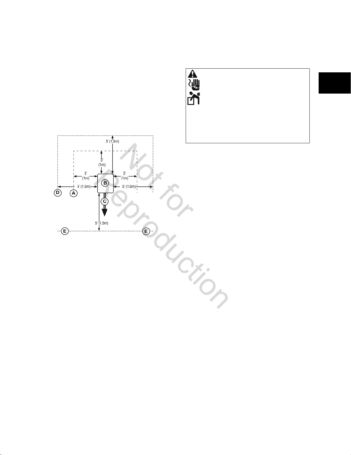
The minimum (MIN) clearances from aerial view of generator
(B) to combustible (D), and non-combustible (A) materials is
shown below.
• These distances are provided to give generator
clearances relative ONLY to combustibles,
generator cooling, and maintenance.
• The minimum distances in the figure are as
shown. All four sides of the generator cannot be
enclosed or restricted, even if the minimum
distances are maintained. DO NOT connect (A)
and/or (D) to (E).
• Do NOT install a roof over the generator, or place
the generator under an existing roof.
• Exhaust (C) must not be allowed to accumulate.
Lifting the Generator
The generator weighs more than 350 pounds (159 kg).
Proper tools, equipment, and qualified personnel should be
used in all phases of handling and moving the generator.
WARNING Hazardous Voltage - Contact with power
lines can cause electric shock or burn. Lifting
Hazard / Heavy Object - Can cause muscle strain
or back injury.
• If lifting or hoisting equipment is used, DO NOT
contact power lines.
• DO NOT lift or move generator without assistance.
• DO NOT lift unit by roof as damage to the generator
will occur.
Lifting pockets are provided at each corner between the base
of the generator and its mounting pad. See Generator
Components for lifting pocket location. Retouch any chipped
paint with supplied touch-up paint.
1
1
A- Non-Combustible material with Fire Resistant Rating of 1
hour or greater.
B- Home Standby Generator
C- Engine Exhaust
D-Combustible Material or Structure with a Fire Resistance
Rating of less than 1 hour.
E- Any structure or material. DO NOT connect (A) and/or (D)
to (E).
5
1
Not for
Reproduction
1
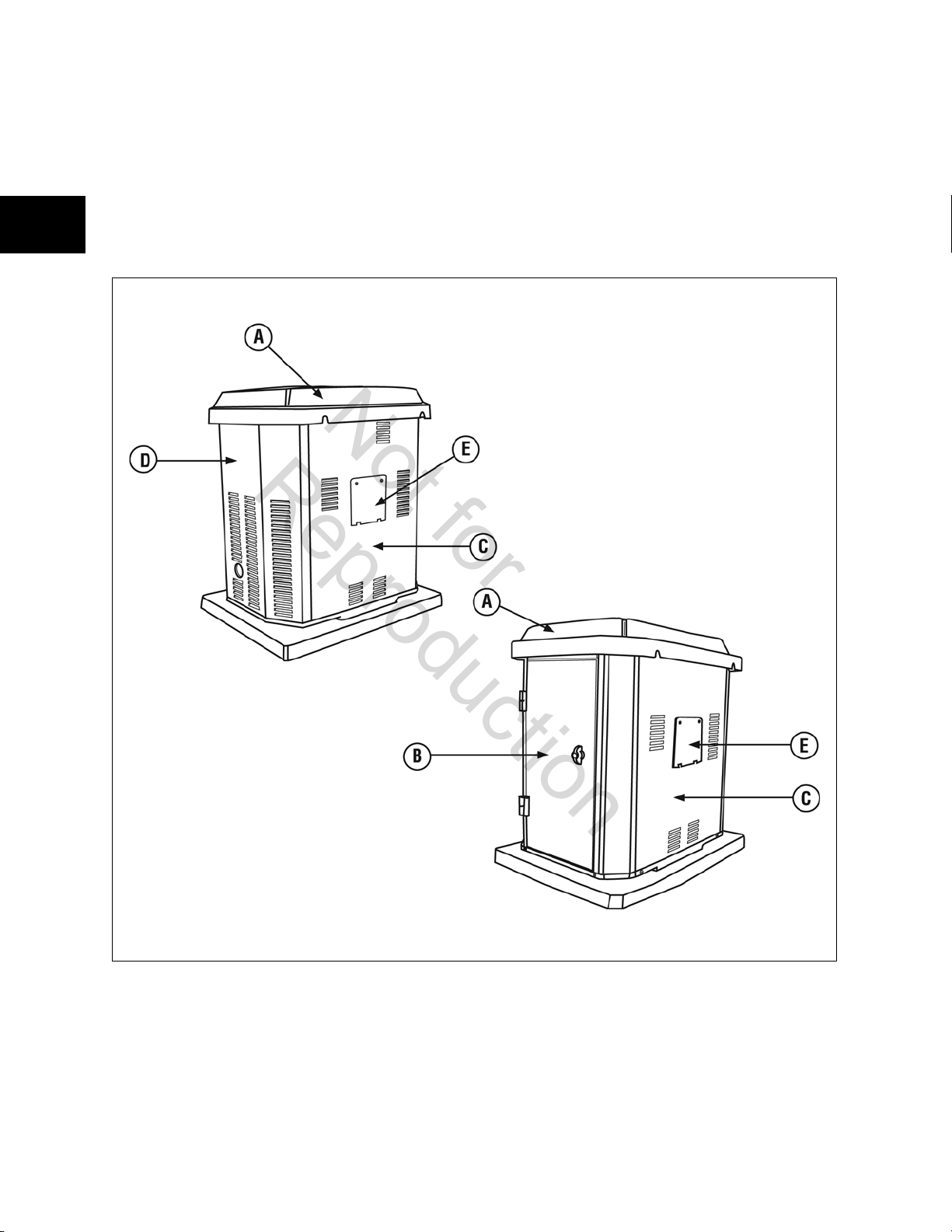
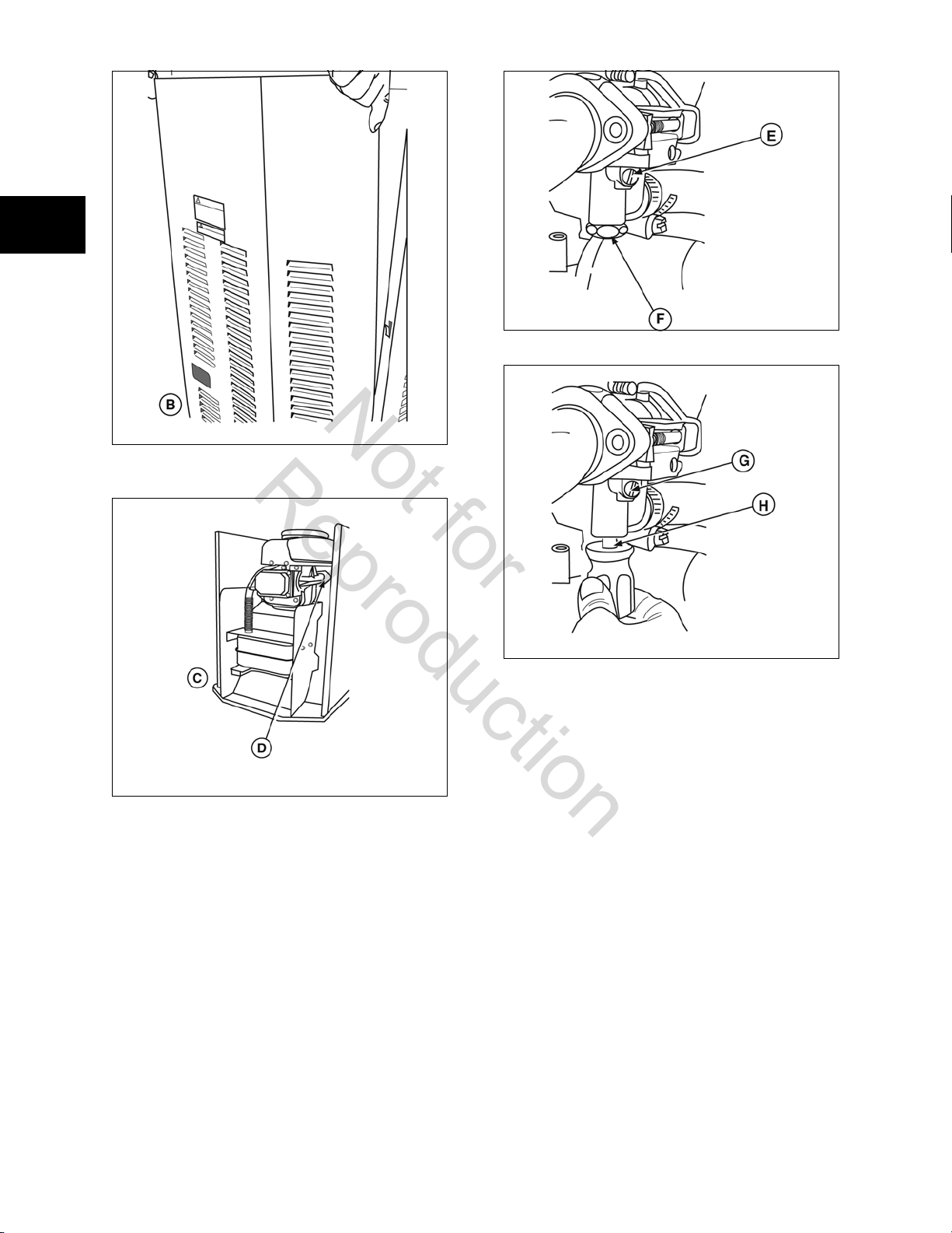
Access To The Generator
The 7kW Home Standby Generator System is equipped with
several access openings and a removable roof (Figure 1).
• Roof (A)
• Access Door (B)
• Side Panel (C)
• Access Panel (D)
• Access Cover for Oil Drain and Oil Filter (E)
Each generator is supplied with a set of identical keys. These
keys fit the locks that secure the access door.
Figure 1
6
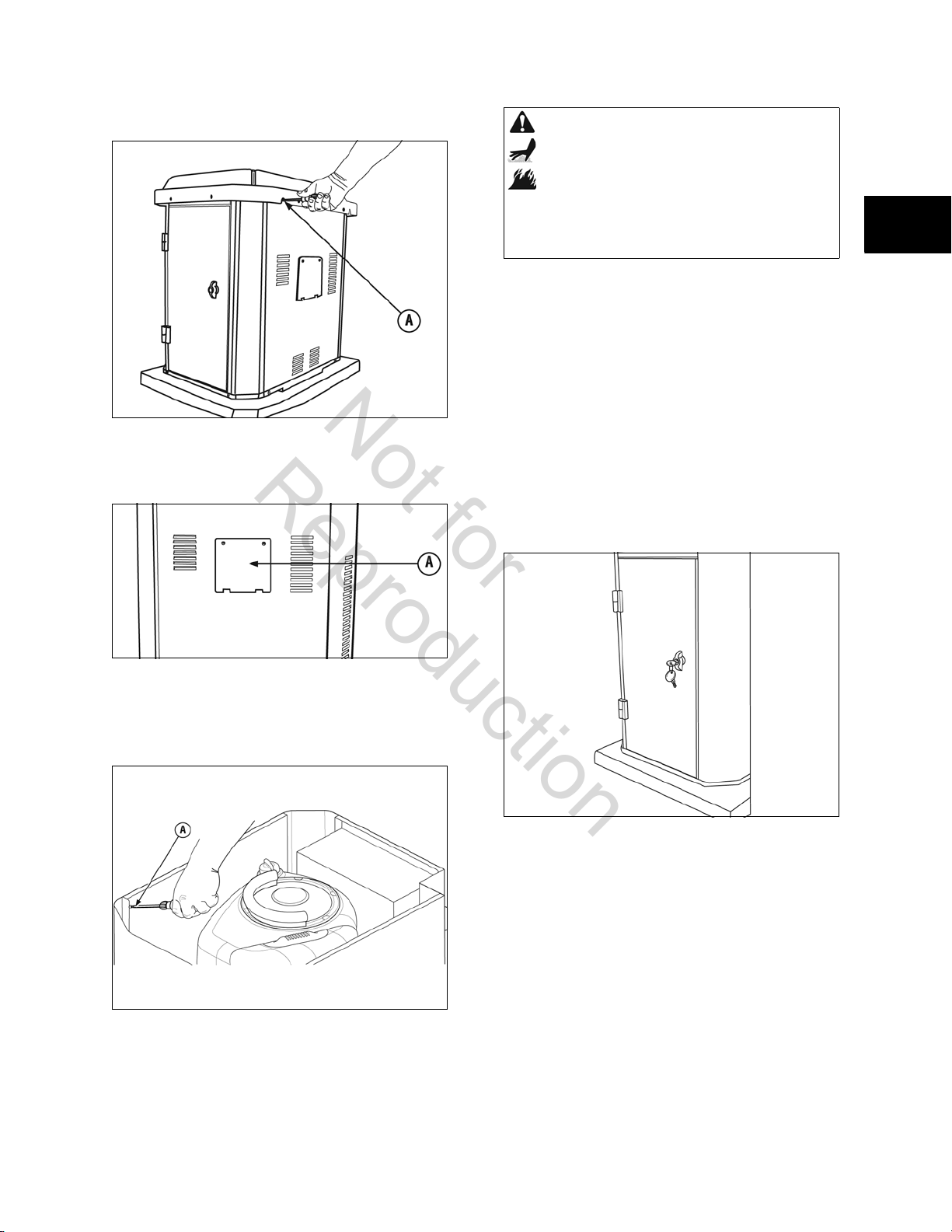
To remove roof:
Not for
Reproduction
Remove the four screws and lift off (A, Figure 2). Reinstall
roof in the reverse order.
WARNING Contact with the muffler area can result in
serious burns. Exhaust heat/gases can ignite
combustibles or structures causing a fire.
• DO NOT touch hot parts and AVOID hot exhaust
gases.
• Allow equipment to cool before touching.
1
Figure 2
To remove access cover:
Remove two screws, tilt cover out, and lift cover off panel (A,
Figure 3). Reinstall cover in the reverse order.
Figure 3
To remove side panels:
1. Remove roof.
2. Remove screws at base of enclosure and along the
side of the control panel (A, Figure 4).
3. Pull panel outward (away) from unit while pulling
panel upward and out of base.
To install side panel:
1. Guide bottom of panel into base.
2. Push panel until flush with sides.
3. Replace panel screw(s).
4. Replace roof and screws.
To open access door:
1. Insert key into lock of access door handle and turn
key one quarter turn clockwise (Figure 5).
1
Figure 4
7
Figure 5
2. Grasp door handle and turn one quarter turn
counterclockwise to open. Remove key.
To close access door:
1. Close door and turn door handle one quarter turn
clockwise.
2. Insert key into lock of door handle and turn key one
quarter turn clockwise. Remove key.
1
Not for
Reproduction
1
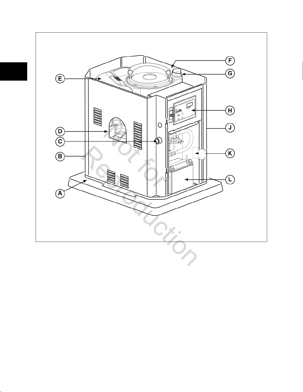
Generator Components
Generator is shown with roof and access doors removed for
clarity.
A - Lifting Pocket — Provided at each corner for lifting
generator.
B - Exhaust Port
engine noise to comply with most residential codes.
C - Fuel Inlet
here.
D - Oil Filter
Filters engine oil to prolong generator life.
E - Air Cleaner
element and foam pre-clean er to protect engine by filtering
dust and debris out of intake air.
8
— High-performance muffler lowers
— Attach appropriate fuel supply to generator
— Located inside access cover on side panel.
— Uses a dry type, UL approved filter
F - Engine Label
numbers.
G - Oil Fill Cap/Dipstick
recommended oil here.
H - Control Panel
maintenance functions. See System Controls.
J - Oil Drain Hose
panel. Provided to facilitate oil changing.
K - Unit Identification Label
serial number.
L - Battery
provides power to start the engine.
— Identifies engine model, type, and code
— Check and fill engine with
— Used for various test, operation, and
— Located inside access cover on side
— Identifies unit by model and
— (Installer-supplied) 12 Volt DC, sealed battery
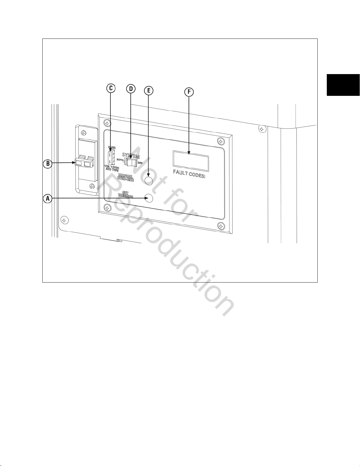
System Controls
Not for
Reproduction
1
1
A - Set Exercise — Used to set the exercise cycle start time
and day-of-the-week. Exercise cycle only occurs in AUTO
mode.
B - Circuit Breaker
and other over-current conditions. Must be ON to supply
power to the automatic transfer switch.
C- 15 Amp Fuse
circuits. If the fuse has ‘blown’ (melted open) or was
removed, the engine cannot crank or start. Replace the fuse
using only an identical ATO 15A fuse.
D - System Switch
important control on the system and is used as follows:
“AUTO” position is the normal operating position. If a utility
power outage is sensed, the system will start the generator.
When utility power is restored, AUTO lets the engine stabilize
internal temperatures, shuts off the generator, and waits for
the next utility power outage.
“OFF” position turns off running generator, prevents unit
from starting, and resets any detected faults.
9
— Protects the generator from shorts
— Protects the generator DC control
— This two-position switch is the most
E - Manual Over-RIde
technician to manually start and stop the generator.
With system switch in the AUTO position, push and hold the
MANUAL OVER-RIDE for six seconds to start the generator.
To turn off the generator, push and hold MANUAL OVERRIDE until engine stops.
F- Digital Display
generator has been running and fault codes. It is used to
schedule maintenance tasks and for troubleshooting
operational problems with the residential generator. A
constant number displayed indicates the total hours of
operation. Fault conditions will flash “FC” followed by a fault
code number.
— This function allows the
— Displays the total number of hours the
1
Not for
Reproduction
1
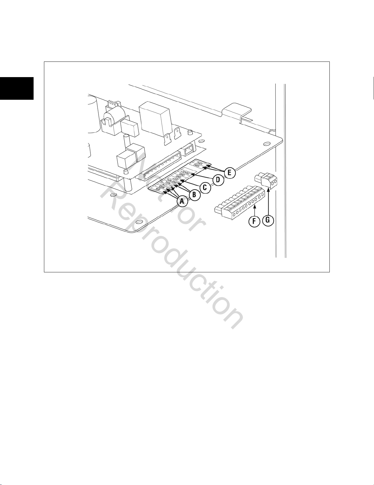
System Connections
Except for the power output and grounding connectors, all signal wire connections are made to removable two- or ten-pin connector
plugs. Compare this illustration with your generator to familiarize yourself wtih the location of these important connections. Count
down to the proper pin location on the control board since visual alignment with the decal can be misleading:
A- Fault Contacts
optional phone dialer or a siren, light, etc. to alert you in case
of a fault. Contacts reverse state (NO goes to NC and vice
versa) upon a fault condition.
B - Transfer Switch Communication
GND to connect to transfer switch control board for
communication interface.
C - Remote LED Output
the remote LED supplied with the generator. The remote LED
will turn on and off in a series of blinks if certain faults are
detected in the generator.
D - +12 Volt DC,.5 Amp Output
Use +12VDC and GND to connect installer-supplied
accessories (siren, light, etc).
E - 240 Volt Utility Connection
utility leads from the transfer switch fuses to the generator.
F - Ten-pin Connector Plug
G - Two-pin Connector Plug
10
— Use NO, COM, and NC to hook up an
— Use TxRx and TxRx
— Use +LED and GND to connect
— Auxiliary power supply.
— Use to connect the 240V
NOTICE:
• For power output connection, use #8 AWG
minimum 300 volt 75°C-90°C copper wire, (ref.
NEC Table 310.16, 100 ft. Use National Electric
Code for correction factors and wire size
calculations).
• For 240 Volt Utility Circuit Connection, use #14
AWG minimum 300 volts 75°C-90°C copper wire.
• For transfer switch communication use #18 AWG
twisted pair conductors, no greater than 200 ft. in
length, 300 volt 75°C-90°C copper wire.
• When connecting to the connector plugs, fasten
only one wire to each connector screw.
• Torque connector plug screws to 7lb.-in.(8 Nm).
Fuel Factors
Not for
Reproduction
An important consideration affecting the performance of the
generator is the type of fuel used. The system was factory
tested and adjusted using either natural gas or liquid propane
(LP). For proper engine function, important NG or LP factors
are:
• Use clean, dry fuel, free of moisture or any
particulate material. Using fuels outside the
following recommended values may cause
performance problems.
• In engines set up to run on propane (LP),
commercial grade HD5 propane with a minimum
fuel energy of 2500 BTUs/ft3 with maximum
propylene content of 5% and butane heavier gas
content of 2.5% and minimum propane content
of 90%.
WARNING Propane and Natural Gas are extremely
flammable and explosive. Fire or explosion can
cause severe burns or death.
• The residential generator is equipped with an
automatic safety fuel shut-off valve.
• DO NOT operate the equipment if the fuel shut-off
valve is missing or inoperative.
Power Decrease at High Altitude or High Temperature
Air density is less at high altitudes, resulting in less available
engine power. Specifically, engine power will decrease 3.5%
for each 1,000 feet (300 meters) above sea level and 1% for
each 10° F (5.6°C) above 77°F (25°C). Generators located in
these conditions must have their transfer switch
programmed appropriately for this power decrease.
Natural Gas LP Vapor
½ Load Full Load ½ Load Full Load
80 C 137 C 33 C 56 C
80,000 B 137,000 B 82,500 B 140,000 B
C = Cubic feet per hour
B = BTU’s per hour
Reconfigure the Fuel System
The engine of your generator is factory calibrated to run on
natural gas (NG). It may also be operated on liquid propane
(LP). There is no additional hardware/equipment required to
switch between either fuel. However, LP fuel inlet pressure
must be between 11 and 14 inches water column at full load
with all gas appliances turned on and operating.
To reconfigure the fuel system for LP use:
1. Set control panel system switch to OFF.
2. Remove 15 Amp fuse.
3. Open oil fill access panel.
4. Remove four screws that secure roof to side panels
and lift off roof.
5. Remove screw at base of enclosure front panel (A,
Figure 6).
1
1
Fuel Consumption
The generator has been factory set to run on natural gas. If
you need to change from natural gas to LP gas, the unit will
need to be reconfigured, as described in Reconfigure the Fuel
System.
The table below provides approximate fuel supply
requirements at half load and full load to ensure effective
generator operation.To check fuel supply pressure, use
#19495, Vacuum Tester.
• Natural gas fuel supply pressure at the generator
fuel inlet port should be between 5 to 7 inches of
water column (in. W.C.) at full load with all gas
appliances turned on and operating.
• LP gas fuel supply pressure should be 11 to 14
inches of water column (in. W.C.) at full load with
all gas appliances turned on and operating.
11
Figure 6
6. Remove two screws at front panel top corners from
inside enclosure.
7. Lift front panel off base (B, Figure 7) and expose
muffler and engine (C,Figure 8).
1
Not for
Reproduction
1
Figure 9
Figure 7
8. Locate the mixer (D).
Figure 10
Figure 8
9. Remove upper brass cover (E, Figure 9) and 3/4” cap
(F).
10. Using a common screwdriver, install supplied plug
into upper chamber (G, Figure 10).
11. Reinstall brass cover (E).
12. Using Insertion Tool #19570, remove existing jet
from lower carburetor inlet (H).
13. Install new jet using Insertion Tool #19570.
14. Replace 3/4” brass cap (F).
15. Reinstall enclosure front panel and roof.
16. Reinstall 15Amp fuse.
17. Set generator circuit breaker to ON position.
The system is now ready to operate automatically using LP
vapor fuel.
12
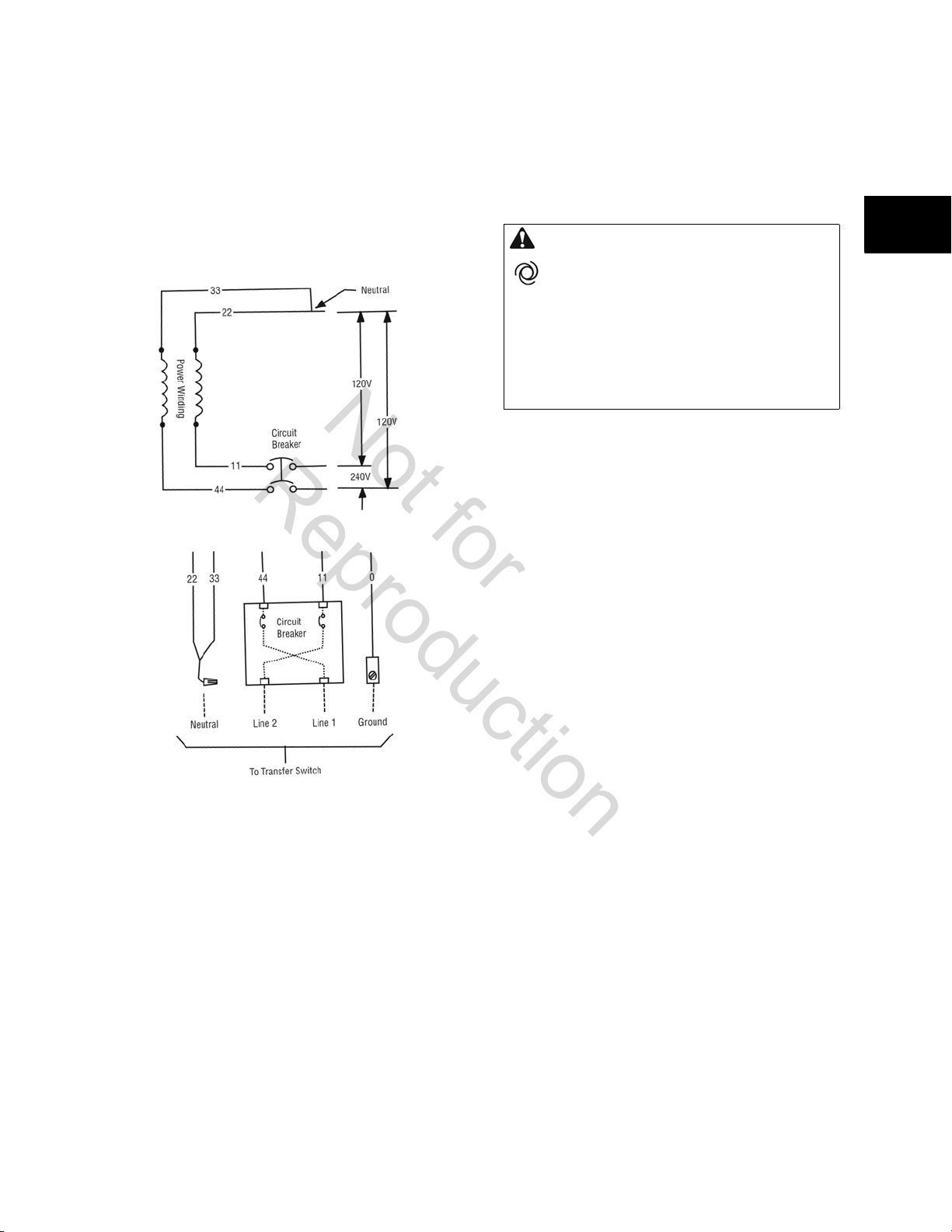
Generator AC Connection System
Not for
Reproduction
A single-phase, three-wire AC connection system is used in
this generator. The stator assembly consists of a pair of
stationary windings with two leads brought out of each
winding. The junction of leads 22 and 33 forms the neutral
lead, as shown schematically and as a wiring diagram. A
complete schematic and wiring diagram can be found in
Section 4 - Generator Specifications.
Automatic Operation
To select automatic operation, proceed as follows:
1. Confirm 15 Amp fuse is installed.
2. Turn on the main distribution panel circuit breaker
that sends utility voltage to the transfer switch.
3. Turn on the generator circuit breaker.
1
CAUTION With the system switch set to AUTO, the
engine may crank and start at any time without
warning.
NOTICE: Neutral is not bonded to ground at generator.
• To prevent possible injury that may be caused by
sudden starts, always set the system switch to OFF if
performing maintenance on the system.
• Remove the 15 Amp fuse before working on or
around the generator or transfer switch.
4. Set the control panel system switch to AUTO.
Checking Automatic Operation
To check the system for proper automatic operation, proceed
as follows:
1. Turn OFF the circuit breaker that sends utility power
to the automatic transfer switch.
NOTICE: When utility voltage is lost and the sensor has timed
out, the engine will crank and start. Let the system go
through its entire automatic operation sequence.
2. With the generator output supplying power, turn ON
the circuit breaker that supplies utility power to the
automatic transfer switch.
3. The automatic transfer switch will transfer loads back
to utility power after a 5 minute minimum run time.
4. The generator will run for an additional one minute
for engine cool down, then shut down.
If utility is restored and generator does not shut down after
10 minutes, set control panel system switch to OFF and
proceed to Section 2 - Troubleshooting.
1
13

Setting Exercise Timer
Not for
Reproduction
The generator is equipped with an exercise timer that will
start and exercise the system once every seven days. During
this exercise period, the unit runs for approximately 20
minutes and then shuts down. Electrical load transfer DOES
NOT occur during the exercise cycle (unless a utility power
outage occurs during the cycle).
A button on the control panel is labeled “Set Exercise” (see
1
System Controls). The day and time at which this button is
pressed is programmed into the control board memory. This
day and time is then used to automatically initiate the system
exercise cycle. The “SET EXERCISE” legend on the control
panel will flash until the set exercise cycle is set.
1
To perform the Set Exercise procedure:
1. Choose the day and time you want the generator to
exercise.
2. On that day and time, press and hold “SET
EXERCISE” for three seconds. “SET EXERCISE” will
flash until the button is held for three seconds, the
“SET EXERCISE” will illuminate for five seconds, and
finally turn off.
For example, if you press “SET EXERCISE” on Sunday
morning at 10:00 AM, the unit will run an exercise cycle every
Sunday at 10:00 AM (+/- 1/2 hour).
“SET EXERCISE” will only work if the unit is in AUTO mode
and this exact procedure is followed. The exerciser will need
to be reset if the 15 Amp fuse is removed or changed, or if
the starting battery is disconnected.
If you want to change the day and time the unit exercises,
simply perform the “Set Exercise” procedure at the new day
and time that you want it to take place.
Generator Maintenance
Before performing any generator maintenance, always
perform the following steps:
1. Set generator’s circuit breaker to its OFF position.
2. Set control panel system switch to OFF.
3. Remove 15 Amp fuse from control panel.
4. Utility voltage is present at generator control panel.
Disconnect utility power before servicing control
panel.
5. Remove roof.
6. After all servicing has been completed, replace fuses
in transfer switch, replace 15 Amp fuse in control
panel, set system switch and circuit breaker ON turn
ON utility power and reset exercise timer. See
Setting Exercise Timer.
For detailed servicing information for the Briggs & Stratton
engine, please refer to the Single Cylinder OHV Repair
Manual (#276781), available from your Briggs & Stratton
source of supply.
Cleaning the Generator
1. Set control panel system switch to OFF.
2. Remove 15 Amp fuse from control panel.
NOTICE: Improper treatment of generator can damage it or
shorten its life.
• DO NOT expose generator to excessive moisture,
dust, dirt, or corrosive vapors.
• DO NOT insert any objects through cooling slots.
3. Use a damp cloth to wipe exterior surfaces clean.
4. Use a soft, bristle brush to loosen caked on dirt, etc.
5. Use a vacuum cleaner to pick up loose dirt and
debris.
6. Use low pressure air (not to exceed 25 psi) to blow
away dirt. Inspect cooling air slots and openings in
the generator. These openings must be kept clean
and unobstructed.
7. Reinstall 15 Amp fuse in control panel.
8. Set generator’s system switch to AUTO.
9. Reset exercise timer. See Setting Exercise Timer.
14
Cooling Fins
Periodically check to make sure the engine cylinder fins, oil
cooler, screens, and mixer ducting are free of leaves, grass,
mulch, or other debris.
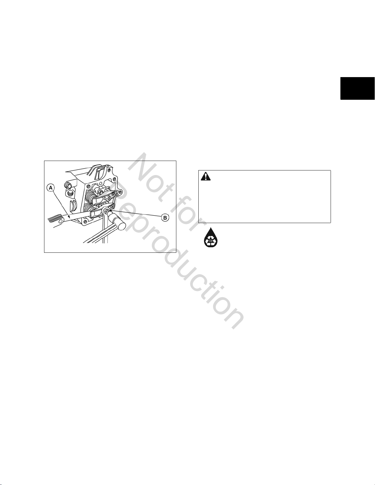
Adjusting the Valve Lash
Not for
Reproduction
The valve lash must be checked every 100 hours of
operation. Measure valve clearance with the engine cold.
To adjust the valve lash, proceed as follows:
1. Turn crankshaft counterclosckwise until piston is at
top dead center on the compression stroke. This
prevents the compression release from holding the
valves open.
2. Insert a narrow screwdriver or rod into the sparkplug
hole as a gauge, then slowly turn crankshaft
counterclockwise until the piston has moved down
the bore by 1/4”.
3. Using a feeler gauge (A, Figure 9), adjust the rocker
nut to obtain the correct clearance as listed below:
• Intake - 0.003 - 0.005 in. (0.08 - 0.13 mm)
• Exhaust - 0.005 - 0.007 in. (0.13 - 0.18 mm)
4. Hold rocker nut and tighten the rocker ball setscrew
(B) to 45 lb-in. (5 Nm).
Oil Service
Checking the Oil Level
Check the engine oil level as follows:
1. Remove the roof to the unit to access the oil fill and
dipstick locations.
2. Remove dipstick. Wipe with clean cloth.
3. Insert and rotate dipstick fully to locked position.
Remove and check oil level.
If oil level is low, remove the oil fill cap and slowly add
recommended oil to bring level to the FULL mark on the
dipstick.
Changing the Oil and Oil Filter
Oil capacity is approximately 2-1/2 quarts (80 ounces or 2.3
liters) when changing both the oil and oil filter. Use only 5W-
30 full- synthetic detergent oil rated for service SJ or higher.
This allows for system operation in the widest range of
temperature and climate conditions.
CAUTION Avoid prolonged or repeated contact with
used motor oil.
• Used motor oil has been shown to cause cancer in
certain laboratory animals.
• Thoroughly wash exposed areas with soap and
water.
1
1
Figure 11
5. Check clearance again and readjust, if necessary.
6. Repeat for the other valve.
Replacing the Spark Plugs
Replace the spark plugs every year. Use only the
recommended spark plugs and make sure they are gapped to
0.030 in. (0.76 mm).
1. Stop the engine and disconnect the wires from the
spark plugs.
2. Clean around the spark plugs and remove them from
the cylinder head.
3. Inspect the spark plugs for wear or damage - replace
as necessary. DO NOT blast clean.
4. Set the gap as specified above and install the cleaned
or new spark plugs into the cylinder heads. Torque
to 180 lb-in. (20 Nm).
KEEP OUT OF REACH OF CHILDREN. DON’T
POLLUTE. CONSERVE RESOURCES. TAKE
USED OIL TO COLLECTION CENTERS.
Change oil and oil filter after every 100 hours of operation. If
the unit is run under dirty or dusty conditions or in extremely
hot weather, change the oil more often.
Use the following instructions to change the oil while the
engine is still warm.
1. Set control panel system switch to OFF.
2. Remove the 15 Amp fuse.
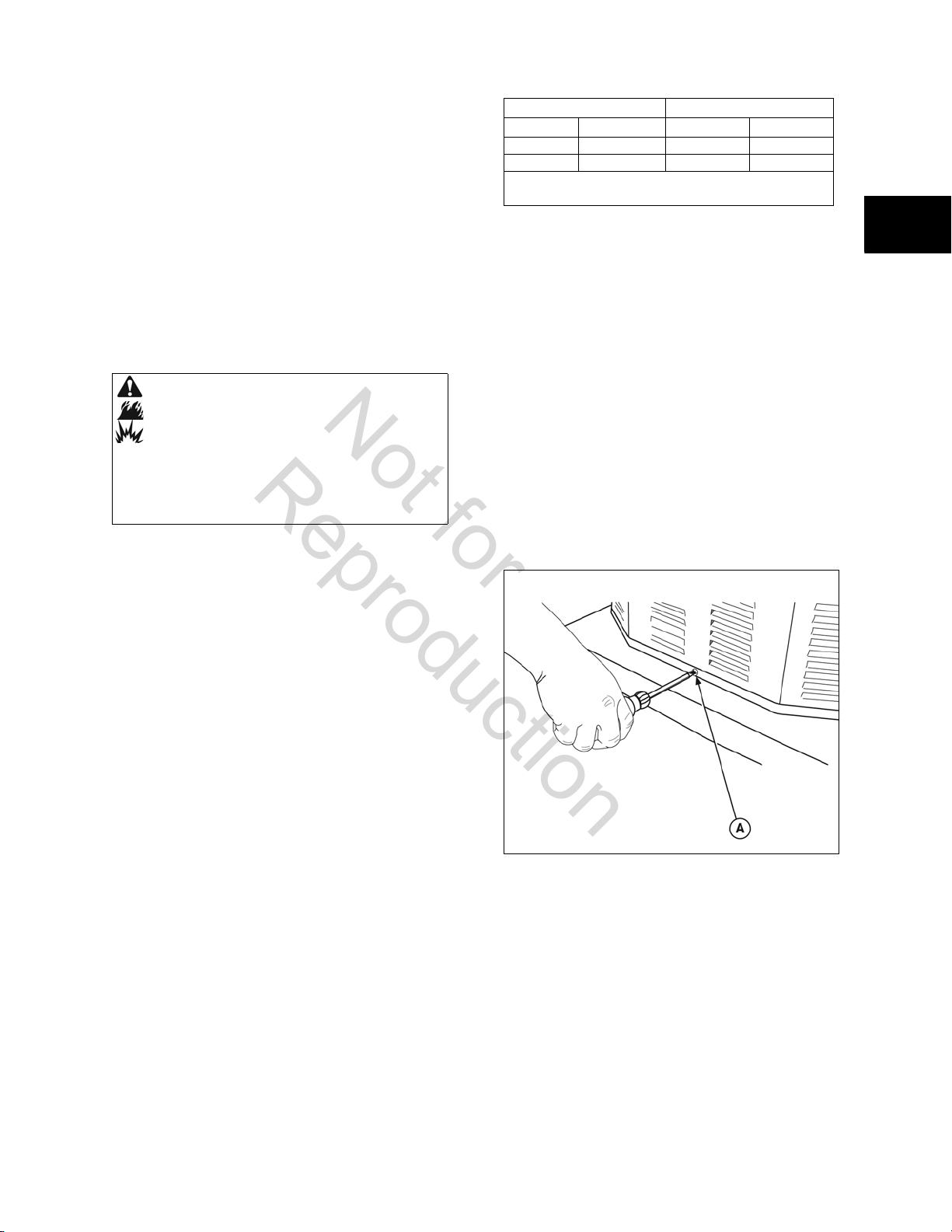
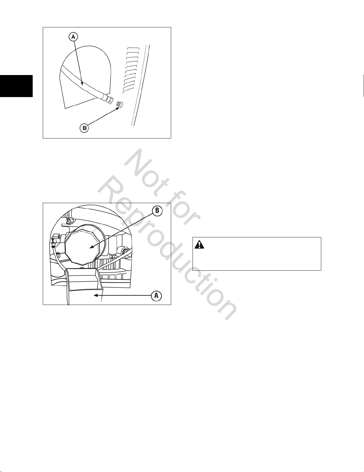
3. Gain access to oil drain hose. It is located inside the
access cover on the side panel (Figure 10).
15
Servicing the Air Cleaner
Not for
Reproduction
The engine air cleaner is one of the most important areas to
maintain. Use only genuine Briggs & Stratton parts which
meet UL requirements for a generator. Clean the foam precleaner (if equipped) every 25 hours and the filter cartridge
every 100 hours of operation. Clean or replace more often in
dusty or dirty conditions.
1
1
Figure 12
4. Place oil drain hose (A) into an approved container.
5. Remove fitting (B) from end of drain hose.
6. When oil has drained, reinstall the fitting on the hose.
7. Gain access to the oil filter. It is located inside the
access cover on the side panel.
8. Place the provided oil filter drain tray (A, Figure 11)
beneath the oil filter (B) and remove the filter.
To service the air cleaner:
1. Unsnap and remove the air filter cover.
2. Remove the air filter cartridge and clean by tapping
gently on a flat surface. Replace if very dirty or
damaged.
3. If equipped, remove the foam pre-cleaner from filter
cartridge and wash in soapy water. Rinse thoroughly
and allow to air dry.
4. Remove the foam filter and clean.
5. Reinstall foam filter and clean air filter cartridge.
Make sure that the rubber seals are in contact with
the mounting all around the filter.
6. Engage the two clips of the air filter cover into their
slots and close the air filter cover. Engage the
locking latch of the filter cover and snap shut.
NOTICE: NEVER use petroleum solvents or pressurized air to
clean the air filter cartridge. Solvents will cause the cartridge
to deteriorate; pressurized air will perforate the paper media.
Battery
The installer must supply a valve-regulated, rechargeable 12
volt starting battery. See Battery in the installation manual.
WARNING Battery posts, terminals, and related
accessories contain lead and lead compounds, chemicals
known to the State of California to cause cancer and
reproductive harm. Wash hands after handling.
Figure 13
9. Coat the gasket of the new filter with clean engine oil.
Turn the new filter clockwise by hand until the gasket
contacts the filter adapter, then tighten 1/2 to 3/4
turn more.
10. Fill the engine with oil until the level is at the FULL
mark on the dipstick.
11. Install and tighten the oil fill cap.
12. Reinstall the 15 Amp fuse.
13. Start and run the generator using the Manual Over-
Ride button.
14. Run the engine for one minute and check for leaks.
Recheck the oil level.
15. Turn control panel system switch to AUTO and reset
the exercise timer. See Resetting the Exercise TImer.
16. Empty oil filter drain tray.
16
The battery receives a trickle charge from the control board
when:
• The generator is running and,
• When utility power is present and the control
panel system switch is either in the AUTO or OFF
position.
The trickle charge will not recharge a battery that is
completely discharged.
Servicing the Battery
Battery service should be performed or supervised only by
personnel who are knowledgeable of batteries and the
required precautions.
If it is necessary to service the battery, proceed as follows:
1. Set control panel system switch to OFF.
2. Remove 15 Amp fuse from control panel.
3. Service or replace battery as required. See Battery in
section under Final Installation Considerations in the
installation manual for battery specifications.
4. Connect red battery cable to battery positive terminal,
Not for
Reproduction
indicated by POSITIVE, POS, or (+).
5. Connect black battery cable to negative battery
terminal, indicated by NEGATIVE, NEG, or (-).
6. Ensure hardware on both positive and negative
battery terminals is secure.
7. Reinstall 15 Amp fuse in control panel.
8. Set control panel system switch to AUTO.
9. Reset exercise time. See Setting Exercise Timer.
DON’T POLLUTE. CONSERVE RESOURCES.
TAKE USED BATTERY TO RECYCLING
COLLECTION CENTERS.
Charging the Battery
If it is necessary to charge the battery, proceed as follows:
1. Set control panel system switch to OFF.
2. Remove 15 Amp fuse from control panel.
3. Disconnect negative (-) battery cable from negative
(-) battery terminal.
NOTICE: Failure to disconnect negative (-) battery cable will
result in equipment failure.
• DO NOT attempt to jump start the generator.
• Damage to equipment resulting from failure to
follow this instruction will void engine and
generator warranty.
4. Charge battery with battery charger at 2 Amps until
battery is fully charged. DO NOT exceed 13.7 volts
when charging.
7. Reinstall 15 Amp fuse in control panel.
CAUTION With the system switch set to AUTO, the
engine may crank and start at any time without
warning.
• To prevent possible injury that may be caused by
sudden starts, always set the system switch to OFF if
performing maintenance on the system.
• Remove the 15 Amp fuse before working on or
around the generator or transfer switch.
8. Set control panel system switch to AUTO.
9. Reset exercise timer. See Setting the Exercise Timer.
Engine Adjustment
There are regional variances in the composition of natural
gas. Each generator leaves the factory set for NG operation. If
the generator frequency is outside the ranges given below,
the combustibility of the gas at the installation site may be
different from the fuel used at the factory.
• Minimum generator frequency is 57 Hz at full
load.
• Maximum generator frequency is 62.0 - 62.5 Hz
at no-load.
1
1
WARNING Storage batteries give off explosive
hydrogen gas during recharging. Slightest spark
will ignite hydrogen and cause explosion. Battery
electrolyte fluid contains acid and is extremely
caustic. Contact with battery contents will cause
severe chemical burns. A battery presents a risk
of electrical shock and high short circuit current.
• DO NOT dispose of a battery in a fire. Recycle the
battery.
• DO NOT allow any open flame, spark, heat, or lit
cigarette during and for several minutes after
charging a battery.
• DO NOT open or mutilate the battery.
• Wear protective gloves, rubber apron, rubber boots,
and rubber gloves.
• Remove watches, rings, or other metal objects.
• Use tools having insulated handles.
5. Connect negative (-) battery cable to negative (-)
battery terminal.
6. Ensure hardware on both positive (+) and negative
(-) terminals is secure.
To adjust the engine for this difference, proceed as follows:
1. Remove four screws and control panel from the
enclosure to expose the main circuit breaker.
2. Connect an accurate frequency meter to line side of
the main circuit breaker or connect tachometer on
spark plug lead.
3. Ensure that the 15 Amp fuse is installed.
4. Set the main circuit breaker ON.
5. Set the control panel system switch to AUTO.
6. Push MANUAL OVER-RIDE on the control panel.
When the engine starts, allow it to warm up for five
minutes.
17
 Loading...