

Page 1
12000 / 15000
Home Generator System
Operator’s Manual
Manual del Operario
Manuel de l'Utilisation
Manual No. 194689GS Rev. F (11/29/06)
Models / Modelos / Modèles
040204
040210
040212
040213
040229
040234
Questions? Help is just a moment away!
Preguntas? La ayuda es justa un momento lejos!
Vous avez des questions? Vous n'avez pas
besoin d'aller loin pour trouver de l'aide!
Call: Home Generator Helpline
Llamada: Línea Directa de Generador de Hogar
Appelez: Ligne Directe de Génératrice la Maison
1-800-743-4115 M-F 8-5 CT
BRIGGSandSTRATTON.COM
Page 2

TABLE OF CONTENTS
2
TABLE OF CONTENTS
TABLE OF CONTENTS . . . . . . . . . . . . . . . . . . . . . . . . . . . . . 2
IMPORTANT SAFETY RULES . . . . . . . . . . . . . . . . . . . . . . 3-5
Hazard Symbols and Meanings. . . . . . . . . . . . . . . . . . . 3
SAVE THESE INSTRUCTIONS. . . . . . . . . . . . . . . . . . . . . . . . 6
INTRODUCTION . . . . . . . . . . . . . . . . . . . . . . . . . . . . . . . . . 6
Installation Assistance . . . . . . . . . . . . . . . . . . . . . . . . . 6
For the Home Owner: . . . . . . . . . . . . . . . . . . . . . . 6
For the Installing Dealer/Contractor: . . . . . . . . . . . 6
OWNER ORIENTATION . . . . . . . . . . . . . . . . . . . . . . . . . . . . 6
Fuel Factors . . . . . . . . . . . . . . . . . . . . . . . . . . . . . . . . . 7
Power Decrease at High Altitude or High
Temperature . . . . . . . . . . . . . . . . . . . . . . 7
Home Generator System Location . . . . . . . . . . . . . . . . 7
Generator Clearances . . . . . . . . . . . . . . . . . . . . . . 7
General Location Guidelines . . . . . . . . . . . . . . . . 7-8
Essential Circuits . . . . . . . . . . . . . . . . . . . . . . . . . . . . . 8
Essential Circuit Selection . . . . . . . . . . . . . . . . . . . 9
UNPACKING . . . . . . . . . . . . . . . . . . . . . . . . . . . . . . . . . . . . 9
Delivery Inspection . . . . . . . . . . . . . . . . . . . . . . . . . . . 9
Shipment Contents . . . . . . . . . . . . . . . . . . . . . . . . . . . 9
KNOW YOUR HOME GENERATOR SYSTEM. . . . . . . . . . . . 10
KNOW YOUR SYSTEM CONTROL PANEL . . . . . . . . . . . . . 11
Access Doors . . . . . . . . . . . . . . . . . . . . . . . . . . . . . . . 12
To Open an Access Door: . . . . . . . . . . . . . . . . . . 12
To Close an Access Door: . . . . . . . . . . . . . . . . . . 12
BEFORE INITIAL START-UP . . . . . . . . . . . . . . . . . . . . . . . 13
Engine Oil . . . . . . . . . . . . . . . . . . . . . . . . . . . . . . . . . . 13
Oil Considerations . . . . . . . . . . . . . . . . . . . . . . . . 13
Battery Connection . . . . . . . . . . . . . . . . . . . . . . . . . . . 13
Gaseous Fuel System . . . . . . . . . . . . . . . . . . . . . . . . . 13
AUTOMATIC OPERATION . . . . . . . . . . . . . . . . . . . . . . . . . 14
Checking Automatic Operation . . . . . . . . . . . . . . . . . . 14
Servicing the System . . . . . . . . . . . . . . . . . . . . . . . . . 14
Setting Exercise Timer . . . . . . . . . . . . . . . . . . . . . . . . 14
FAULT DETECTION SYSTEM . . . . . . . . . . . . . . . . . . . . . . . 15
Reset Fault Detection System . . . . . . . . . . . . . . . 15
No LED - Discharged Battery . . . . . . . . . . . . . . . 15
Low Battery Voltage . . . . . . . . . . . . . . . . . . . . . . 15
Low Oil Pressure . . . . . . . . . . . . . . . . . . . . . . 15-16
Low Voltage . . . . . . . . . . . . . . . . . . . . . . . . . . . . 16
Engine Fail To Start . . . . . . . . . . . . . . . . . . . . . . . 16
Low Frequency. . . . . . . . . . . . . . . . . . . . . . . . . . . 16
Engine Overspeed . . . . . . . . . . . . . . . . . . . . . . . . 16
Oil Temperature High . . . . . . . . . . . . . . . . . . . . . 16
Transfer Switch Fault . . . . . . . . . . . . . . . . . . . . . . 16
GENERATOR MAINTENANCE . . . . . . . . . . . . . . . . . . . . . . 17
Changing Engine Oil . . . . . . . . . . . . . . . . . . . . . . . . . . 17
To Clean the Generator . . . . . . . . . . . . . . . . . . . . . . . . 17
When Calling the Factory . . . . . . . . . . . . . . . . . . . . . . 17
STORAGE . . . . . . . . . . . . . . . . . . . . . . . . . . . . . . . . . . . . . 17
TROUBLESHOOTING . . . . . . . . . . . . . . . . . . . . . . . . . . . . . 18
WARRANTY . . . . . . . . . . . . . . . . . . . . . . . . . . . . . . . . . . . . 19
ESPAÑOL . . . . . . . . . . . . . . . . . . . . . . . . . . . . . . . . . . . 20-37
FRANÇAIS . . . . . . . . . . . . . . . . . . . . . . . . . . . . . . . . . . 38-56
Copyright © 2006 Briggs & Stratton Power Products Group,
LLC. All rights reserved. No part of this material may be
reproduced or transmitted in any form by any means without
the express written permission of Briggs & Stratton Power
Products Group, LLC.
Page 3
SAFETY RULES
3
IMPORTANT SAFETY RULES
The safety alert symbol ( ) is used with a signal word
(DANGER, CAUTION, WARNING), a pictorial and/or a safety
message to alert you to hazards. DANGER indicates a hazard
which, if not avoided, will result in death or serious injury.
WARNING indicates a hazard which, if not avoided, could
result in death or serious injury. CAUTION indicates a hazard
which, if not avoided, might result in minor or moderate
injury. NOTICE indicates a situation that could result in
equipment damage. Follow safety messages to avoid or
reduce the risk of injury or death.
The manufacturer cannot possibly anticipate every possible
circumstance that might involve a hazard. The warnings in
this manual, and the tags and decals affixed to the unit are,
therefore, not all-inclusive. If you use a procedure, work
method or operating technique that the manufacturer does
not specifically recommend, you must satisfy yourself that it
is safe for you and others. You must also make sure that the
procedure, work method or operating technique that you
choose does not render the generator unsafe.
NOTE: Your generator is equipped with a spark arrester
muffler. The spark arrester must be maintained in effective
working order by the owner/operator. In the State of
California, a spark arrester is required by law (Section 4442
of the California Public Resources Code). Other states may
have similar laws. Federal laws apply on federal lands.
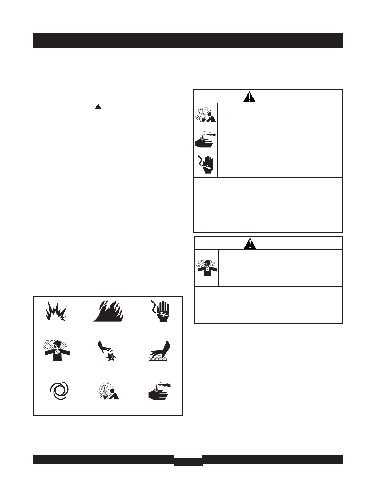
Hazard Symbols and Meanings
SAVE THESE INSTRUCTIONS
Explosion
Fire
Electrical Shock
Rotating Parts
Hot Surface
Toxic Fumes
Chemical BurnExplosive PressureAuto Start
WARNING
Storage batteries give off explosive hydrogen gas
during recharging.
Slightest spark will ignite hydrogen and cause
explosion.
Battery electrolyte fluid contains acid and is
extremely caustic.
Contact with battery contents will cause severe
chemical burns.
A battery presents a risk of electrical shock and
high short circuit current.
• DO NOT dispose of battery in a fire.
• DO NOT allow any open flame, spark, heat, or lit cigarette
during and for several minutes after charging a battery.
• DO NOT open or mutilate the battery.
• Wear protective goggles, rubber apron, and rubber gloves.
• Remove watches, rings, or other metal objects.
• Use tools with insulated handles.
WARNING
Running engine gives off carbon monoxide, an
odorless, colorless, poison gas.
Breathing carbon monoxide can cause headache,
fatigue, dizziness, vomiting, confusion, seizures,
nausea, fainting or death.
• Operate generator ONLY outdoors.
• Install a battery operated carbon monoxide alarm near the
bedrooms.
• Keep exhaust gas from entering a confined area through
windows, doors, ventilation intakes, or other openings.
Page 4
SAFETY RULES
4
WARNING
Generator produces hazardous voltage.
Failure to properly ground generator can result in
electrocution.
Failure to isolate generator from power utility can
result in death or injury to electric utility workers
due to backfeed of electrical energy.
• When using generator for backup power, notify utility company.
• DO NOT touch bare wires or receptacles.
• DO NOT use generator with electrical cords which are worn,
frayed, bare or otherwise damaged.
• DO NOT handle generator or electrical cords while standing in
water, while barefoot, or while hands or feet are wet.
• If you must work around a unit while it is operating, stand on
an insulated dry surface to reduce shock hazard.
• DO NOT allow unqualified persons or children to operate or
service generator.
• In case of an accident caused by electrical shock, immediately
shut down the source of electrical power and contact the local
authorities. Avoid direct contact with the victim.
• Despite the safe design of the Home Generator System, operating
this equipment imprudently, neglecting its maintenance or being
careless can cause possible injury or death.
• Remain alert at all times while working on this equipment.
NEVER work on the equipment when you are physically or
mentally fatigued.
• Before performing any maintenance on the generator,
disconnect the battery cable indicated by a NEGATIVE, NEG or
(-) first. When finished, reconnect that cable last.
• After your Home Generator System is installed, the generator
may crank and start without warning any time there is a power
failure. To prevent possible injury, always set the generator’s
system switch to OFF, remove the service disconnect from the
disconnect box AND remove the 15 Amp fuse BEFORE working
on the equipment.
WARNING
Propane and Natural Gas are extremely
flammable and explosive.
Fire or explosion can cause severe burns or
death.
• Install the fuel supply system according to applicable fuel-gas
codes.
• Before placing the Home Generator System into service, the
fuel system lines must be properly purged and leak tested.
• After the generator is installed, you should inspect the fuel
system periodically.
• NO leakage is permitted.
• DO NOT operate engine if smell of fuel is present or other
explosive conditions exist.
• DO NOT smoke around the generator. Wipe up any oil spills
immediately. Ensure that no combustible materials are left in
the generator compartment. Keep the area near the generator
clean and free of debris.
WARNING
Contact with muffler area can result in serious
burns.
Exhaust heat/gases can ignite combustibles or
structures causing a fire.
• DO NOT touch hot parts and AVOID hot exhaust gases.
• Allow equipment to cool before touching.
• DO NOT install the generator closer than 5 feet (1.5m) from any
combustibles or structures with combustible walls having a fire
resistance rating of less than 1 hour.
• Keep at least 3 ft. (91 cm) clearance on all sides of generator
including overhead.
• Code of Federal Regulation (CFR) Title 36 Parks, Forests, and
Public Property require equipment powered by an internal
combustion engine to have a spark arrester, maintained in
effective working order, complying to USDA Forest service
standard 5100-1C or later revision. In the State of California a
spark arrester is required under section 4442 of the California
Public resources code. Other states may have similar laws.
Page 5
SAFETY RULES
5
CAUTION
Excessively high operating speeds increase risk of injury
and damage to generator.
Excessively low speeds impose a heavy load.
• DO NOT tamper with governed speed. Generator supplies
correct rated frequency and voltage when running at governed
speed.
• DO NOT modify generator in any way.
NOTICE
Improper treatment of generator can damage it and
shorten its life.
• Use generator only for intended uses.
• If you have questions about intended use, ask dealer or contact
Briggs and Stratton.
• Operate generator only on level surfaces.
• Adequate, unobstructed flow of cooling and ventilating air is
critical to correct generator operation.
• The Oil Fiil, Oil Drain and the Control Panel doors must be
installed whenever the unit is running.
• DO NOT expose generator to excessive moisture, dust, dirt, or
corrosive vapors.
• Despite the safe design of the Home Generator System, operating
this equipment imprudently, neglecting its maintenance or being
careless can cause possible injury or death.
• Remain alert at all times while working on this equipment.
NEVER work on the equipment when you are physically or
mentally fatigued.
• DO NOT start engine with air cleaner or air cleaner cover
removed.
• DO NOT insert any objects through cooling slots.
• DO NOT use the generator or any of its parts as a step.
Stepping on the unit can cause stress and break parts. This
may result in dangerous operating conditions from leaking
exhaust gases, fuel leakage, oil leakage, etc..
• If connected devices overheat, turn them off and disconnect
them from generator.
• Shut off generator if:
-electrical output is lost;
-equipment sparks, smokes, or emits flames;
-unit vibrates excessively.
WARNING
Starter and other rotating parts can entangle
hands, hair, clothing, or accessories.
• NEVER operate generator without protective housing or covers.
• DO NOT wear loose clothing, jewelry or anything that may be
caught in the starter or other rotating parts.
• Tie up long hair and remove jewelry.
CAUTION
Installing the 15A fuse could cause the engine to
start.
• Observe that the 15 Amp fuse has been removed from the
control panel for shipping.
• DO NOT install this fuse until all plumbing and wiring has been
completed and inspected.
NOTICE
Exceeding generators wattage/amperage capacity can
damage generator and/or electrical devices connected to it.
• See “Essential Circuits”.
• Start generator and let engine stabilize before connecting
electrical loads.
Page 6

INSTALLATION
6
SAVETHESE INSTRUCTIONS
This manual contains important instructions that should be
followed during installation and maintenance of the generator
and battery.
INTRODUCTION
Thank you for your purchase of a Briggs & Stratton Home
Generator System (HGS). This product is intended for use as
an optional home standby system which provides an
alternate source of electric power and to serve loads such as
heating, refrigeration systems, and communication systems
that, when stopped during any power outage, could cause
discomfort, or the like. This product does not qualify for
emergency standby as defined by NFPA 70 (NEC).
Briggs and Stratton has made every effort to provide for a
safe, streamlined and cost-effective installation. Because
each installation is unique, it is impossible to know of and
advise the trade of all conceivable procedures and methods
by which installation might be achieved. Neither could we
know of possible hazards and/or the results of each method
or procedure. For these reasons,
Only current licensed electrical and plumbing
contractors should attempt HGS installations.
Installations must strictly comply with
all applicable codes, industry standards
and regulations.
Your Briggs & Stratton Home Generator System is supplied
with this “Operator’s Manual” and a separate “Installation
Manual”. These are important documents and should be
retained by the owner after the installation has been
completed.
Installation Assistance
For the Home Owner:
To help you make informed choices and communicate
effectively with your installation contractor(s),
Read and understand the
Owner Orientation Section of this manual
BEFORE
contracting or starting
your HGS installation.
To arrange for proper installation, contact the store at which
you purchased your Briggs & Stratton Home Generator
System, your dealer, a licensed electrician or your utility
power provider.
The HGS Warranty is VOID unless the system is installed
by licensed electrical and plumbing professionals.
For the Installing Dealer/Contractor:
For most applications, the Installation manual contains all the
information required to properly install and start the Home
Generator System. This Operator’s Manual describes
essential circuit selection, routine operation and owner
maintenance procedures.
If you need more information, call 1-800-743-4115, between
8:00 AM and 5:00 PM CT.
The Emission Control System for this generator is warranted
for standards set by the U.S. Environmental Protection
Agency and by the California Air Resources Board (CARB).
OWNER ORIENTATION
This section provides Home Generator System owners with
the information necessary to achieve the most satisfactory
and cost effective installation possible.
The illustrations are for typical circumstances and are meant
to familiarize you with the installation options available with
your Home Generator System. A thorough understanding of
these options will provide fundamental control over the cost
of your installation, as well as ensure your final satisfaction
and security.
Federal and local codes, appearance, noise levels, fuel types,
and distances are the factors that must be considered when
negotiating with an installation professional. Remember that
as the distance from the existing electrical service and
gaseous fuel supply increases, equal compensations in
piping and wiring materials must be allowed for. This is
necessary to comply with local codes and overcome
electrical voltage drops and gaseous fuel pressure drops.
The factors mentioned above will have a direct affect on
the overall price of your Home Generator System
installation.
NOTE: In some areas you may need to acquire electrical
permits for installing the Home Generator System, building
permits for installing gas lines, and permits for noise
allowances. Your installer should check your local codes AND
obtain the permits before installing the system.
Page 7
INSTALLATION
7
Fuel Factors
An important consideration affecting the entire installation is
the type of fuel used by your Home Generator System. The
system was factory tested and adjusted using natural gas as
a fuel. Liquid propane (LP) may also be used as a fuel (see
the Installation Manual).
Although there are specific factors that are inherent to each of
these fuels, your location and the duration of possible utility
interruptions should guide your selection of fuel type. For
urban installations, Natural Gas (if available) should be your
fuel of choice. For remote installations, a Liquefied Petroleum
(LP) tank might better meet your needs.
For proper engine function, the following fuel guidelines are
recommended:
• Use clean, dry fuel, free of moisture or any particulate
material. Using fuels outside the following recommended
values may cause performance problems.
In engines set up to run on propane (LP) gas,
commercial grade HD5 propane with a minimum fuel
energy of 2500 BTUs/ft
3
with maximum propylene
content of 5% and butane and heavier gas content of
2.5% and minimum propane content of 90%.
Power Decrease at High Altitude or High Temperature
Air density is less at high altitudes, resulting in less available
engine power. Specifically, engine power will decrease 3.5%
for each 1,000 feet (300 meters) above sea level and 1% for
each 10° F (5.6°C) above 77°F (25°C). Make sure you and
your installer consider these factors when determining total
generator load.
Generator Location
The actual physical location of your HGS has a direct affect on:
1. The amount of plumbing required to fuel your generator.
2. The amount of wiring required to control and connect
your generator.
NOTE: Specific location guidelines are discussed in the
Installation Manual. Acquaint yourself with that information
and confer with your installer. Be sure to ask how your site
might affect installation costs and compliance with local
codes and standards.
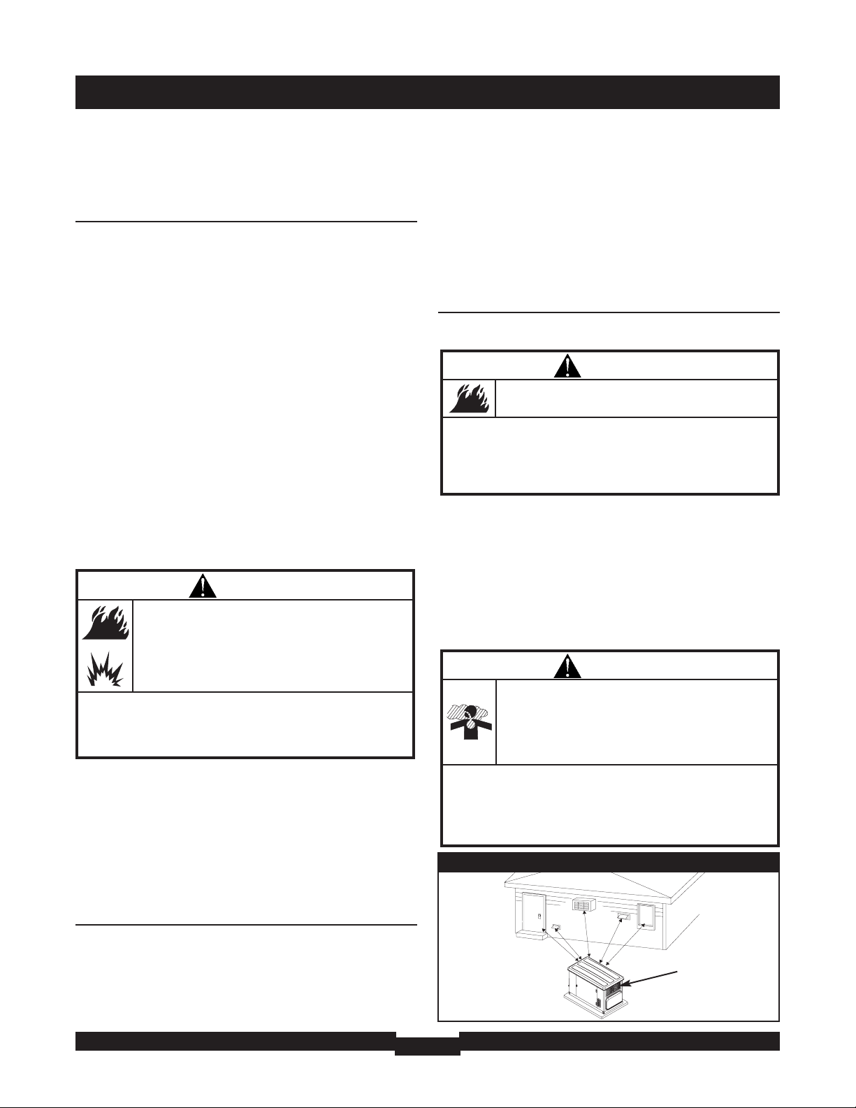
Home Generator System Location
Before installing generator, consult with homeowner and convey
the following guidelines which may affect the desired location.
Generator Clearances
Install generator outdoors in an area which will not accumulate
deadly exhaust gas. DO NOT install generator where exhaust
gas could accumulate and enter inside or be drawn into a
potentially occupied building. Ensure exhaust gas is kept away
from any windows, doors, ventilation intakes or other
openings that can allow exhaust gas to collect in a confined
area (Figure 1). Prevailing winds and air currents should be
taken into consideration when positioning generator.
WARNING
Propane and Natural Gas are extremely
flammable and explosive.
Fire or explosion can cause severe burns or
death.
• The Home Generator System is equipped with an automatic
safety gas “fuel shut-off” valve.
• DO NOT operate the equipment if the “fuel shut-off” valve is
missing or inoperative.
Figure 1 — Home Generator System Location
Exhaust Port
WARNING
Running engine gives off carbon monoxide, an
odorless, colorless, poison gas.
Breathing carbon monoxide can cause headache,
fatigue, dizziness, vomiting, confusion, seizures,
nausea, fainting or death.
• Operate generator ONLY outdoors.
• Install a battery operated carbon monoxide alarm near the
bedrooms.
• Keep exhaust gas from entering a confined area through
windows, doors, ventilation intakes, or other openings.
WARNING
Exhaust heat/gases can ignite combustibles or
structures causing a fire.
• DO NOT install the generator closer than 5 feet (1.5m) from
any combustibles or structures with combustible walls having
a fire resistance rating of less than 1 hour.
• Keep at least 3 ft. (91 cm) clearance on all sides of generator
including overhead.
Page 8

INSTALLATION
8
General Location Guidelines
• Install the unit outdoors ONLY.
• Place the unit in a prepared location that is flat and has
provisions for water drainage.
• Install the unit in a location where sump pump discharge,
rain gutter down spouts, roof run-off, landscape irrigation,
or water sprinklers will not flood the unit or spray the
enclosure and enter any air inlet our outlet openings.
• Install the unit where the location of any services such as
phone, electrical, fuel, air conditioning, irrigation, including
covered, concealed and underground services will not be
affected or obstructed.
• Install the unit where air inlet and outlet openings will not
become obstructed by leaves, grass, snow, etc. If
prevailing winds will cause blowing or drifting, you may
need to construct a windbreak to protect the unit.
• Install the generator as close as possible to the Transfer
Switch to reduce the length of wiring and conduit.
• Install the generator as close as possible to the fuel supply
to reduce length of pipes.
IMPORTANT: Laws or local codes may regulate the distance
to the fuel supply.
The Home Generator System is shipped already attached to
its mounting pad. Unless mandated by local code, a concrete
slab is not required.
If mandated by local code, construct a concrete slab at least
3 inches thick and 6 inches longer and wider than the unit.
Attach unit to slab with 1/4” diameter (minimum) masonry
anchor bolts long enough to retain the unit.
Essential Circuits
As a Home Generator System owner, it is important that you
clearly identify the circuits in your building that are "essential"
to you.
It is important that your installer understand which
circuits
you want to include as "Essential Circuits". Depending on the
power consumed by these circuits, most or all of them can
be switched to the Home Generator System for the duration
of normal power interruption.
The wattage reference guide shown in Figure 2 will assist you
with your decision-making process. It provides the wattage
used by many ordinary household devices. Use it as a guide
when selecting your essential circuits. Review this information
with your installer and ask about any technical considerations
that might affect the cost of your installation.
Device
Running
Watts
Air Conditioner (12,000 Btu)*
1700
Air Conditioner (24,000 Btu)*
3800
Air Conditioner (40,000 Btu)*
6000
Battery Charger (20 Amp)
500
Circular Saw (6-1/2")
800 to 1000
Clothes Dryer (Electric)*
5750
Clothes Dryer (Gas)*
700
Clothes Washer*
1150
Coffee Maker
1750
Compressor (1 HP)*
2000
Compressor (1/2 HP)*
1400
Compressor (3/4 HP)*
1800
Curling Iron
700
Dehumidifier*
650
Electric Blanket
400
Electric Range (per element)
1500
Electric Skillet
1250
Freezer*
700
Furnace Fan (3/5 HP)*
875
Garage Door Opener*
500 to 750
Hair Dryer
1200
Hand Drill
250 to 1100
Iron
1200
Jet Pump*
800
Light Bulb
100
Microwave Oven
700 to 1000
Milk Cooler*
1100
Oil Burner on Furnace
300
Oil Fired Space Heater (140,000 Btu)
400
Oil Fired Space Heater (30,000 Btu)
150
Oil Fired Space Heater (85,000 Btu)
225
Radio
50 to 200
Refrigerator
700
Slow Cooker
200
Submersible Pump (1 HP)*
2000
Submersible Pump (1/2 HP)*
1500
Submersible Pump (1-1/2 HP)*
2800
Sump Pump*
800 to 1050
Table Saw (10")*
1750 to 2000
Television
200 to 500
Toaster
1000 to 1650
Figure 2 — Wattage Reference Guide
*Allow three (3) times listed watts for starting device
Page 9

INSTALLATION
9
Essential Circuit Selection
When selecting the essential circuits that will be switched to
“Standby Power,” it is important that the sum of the combined
circuit loads does not exceed the wattage/amperage capacity of
the generator. To help you with your selection of essential
circuits, please consider the following:
Add up the total wattage of all electrical devices to be
connected at one time. This total should NOT be greater
than the generator’s wattage capacity.
The rated wattage of lights can be taken from light bulbs.
The rated wattage of tools, appliances and motors can
usually be found on a data plate or decal affixed to the
device.
If the appliance, tool or motor nameplate does not list
wattage, multiply volts times the ampere rating to
determine watts (Volts x Amps = Watts).
Some electric motors (induction types) require about three
times more watts of power for starting than for running.
This surge lasts for only a few seconds. Be sure you allow
for this high starting wattage when selecting electrical
devices that will be energized by the Home Generator
System:
• Figure the watts required to start the largest motor.
• Add that to the total running watts of all other
connected loads.
This Briggs & Stratton Home Generator System complies
with the following “stationary standby power rating”:
The standby power rating is applicable for supplying power
for the duration of normal power interruption. NO sustained
overload capability is available for this rating.
This rating is applicable to installations served by a reliable
normal utility source. This rating is only applicable to
variable loads with an average load factor of 80% of the
standby rating. The standby rating is only applicable for
optional standby power where the generator set serves as
the backup to the normal utility source.
Use the “Wattage Reference Guide” provided and mark those
circuits you consider “critical” or “essential”. Make sure you
and your installer consider the system’s altitude above sea
level and the ambient temperature range when determining
total generator load.
IMPORTANT: When using the 100 Amp or 200 Amp transfer
switch with the Home Generator System, you must turn off any
non essential loads. Failure to turn off non essential loads could
overload the generator causing it to shut down. Some examples
of non essential loads are as follows:
• Pool pump
• Hot tub
• Electric hot tub and/or pool heaters
• Central air conditioners
• Electric hot water heaters
• Electric range and/or oven
• Arc welder
• Non essential electric heaters
UNPACKING
Refer to the Installation Manual for detailed unpacking
instructions, if desired.
Delivery Inspection
After removing the carton, carefully inspect the Home
Generator System for any damage that may have occurred
during shipment.
IMPORTANT: If loss or damage is noted at time of delivery,
have the person(s) making delivery note all damage on the
freight bill and affix his signature under the consignor's
memo of loss or damage. If loss or damage is noted after
delivery, separate the damaged materials and contact the
carrier for claim procedures. Missing or damaged parts are
not warranted.
Shipment Contents
The Home Generator System is supplied with:
• Home Generator System
• Pre-attached mounting pad
• One flexible hook-up hose
• Installation and start-up manual
• Operator’s manual
• Illustrated parts list manual
• Installation checklist
• Two access door keys
• Four lifting hole plugs
• Oil fill spout
• One spare 15A fuse
• 2 Pole connector - 240V from house
• 10 Pole connector - Sensing and control wires
• Air intake engine cover
• Alternator cover
• Diagnostic LED kit (red LED/plate/screws (2))
Page 10
FEATURES AND CONTROLS
10
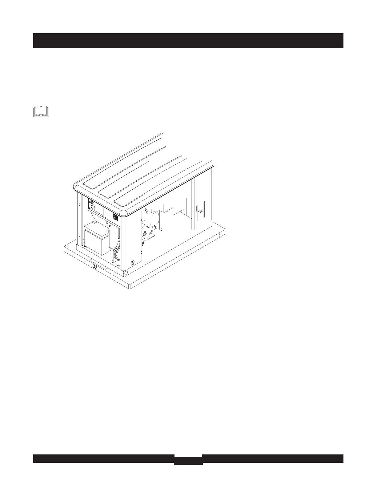
KNOW YOUR HOME GENERATOR SYSTEM
Read this Operator’s Manual and safety rules before operating your generator.
Compare the illustrations with your generator to familiarize yourself with the locations of various controls and
adjustments. Save this manual for future reference.
Page 11

FEATURES AND CONTROLS
11
Page 12

INSTALLATION
12
Access Doors
The Home Generator System is equipped with an enclosure
that has three access doors (Figure 3). The doors are named
for a significant component located behind them. Starting
with the side that has the fuel connection and proceeding
clockwise, the doors are named:
• Oil Fill door
• Control Panel door
• Oil Drain door
Each Home Generator System is equipped with two identical
keys. These keys fit the locks that secure the access doors.
To Open an Access Door:
1. Insert key into lock of access door you wish to open and
turn one quarter turn counterclockwise.
2. Grasp door’s handle and turn one quarter turn
counterclockwise to open. Remove key.
To Close an Access Door:
1. Close door and turn doors handle one quarter of a turn
clockwise.
2. Insert key into lock of access door and turn one quarter
turn clockwise. Remove key.
Page 13
INSTALLATION
13
BEFORE INITIAL START-UP
Engine Oil
This engine is shipped from the factory filled with the
recommended oil. Before starting the engine, check oil level
and ensure that engine is serviced as described in the engine
operator’s manual.
Oil Considerations
Your Home Generator System is equipped with an engine
that has been pre-run at the factory and does not require the
traditional “break-in” procedure.
The system is filled with synthetic oil (API SJ/CF 5W-30W).
This allows for system operation in the widest range of
temperature and climate conditions.
NOTE: The use of synthetic oil DOES NOT alter the required
oil change intervals described in the engine operator’s
manual.
Battery Connection
The Home Generator System is supplied with a 12 Volt DC
55 Amp-Hour, valve regulated battery. It is a sealed, lead-acid
rechargeable battery. It is installed in the unit and the battery
cables are connected at the factory. The generator’s 15 Amp
fuse has been removed to prevent the unit from starting
during shipping.
NOTE: With the battery installed, all wiring to transfer switch
and Home Generator System completed, utility power
supplied to the Automatic Transfer Switch, and the unit in
AUTO mode, the battery receives a trickle charge while the
engine is not running. The trickle charger cannot be used to
recharge a battery that is completely discharged.
Gaseous Fuel System
• Ensure that all fuel connections are tight, secure and
without leaks.
• Ensure that all shutoff valves are OPEN and that adequate
pressure is available (see installation manual).
NOTICE
Any attempt to crank or start the engine before it has been
properly serviced with the recommended oil will result in
equipment failure.
• Refer to engine manual for oil fill information.
• Damage to equipment resulting from failure to follow this
instruction will void warranty.
CAUTION
Installing the 15A fuse could cause the engine to
start.
• DO NOT install this fuse until all plumbing and wiring has been
completed and inspected.
WARNING
Propane and Natural Gas are extremely
flammable and explosive.
Fire or explosion can cause severe burns or
death.
• DO NOT operate engine if smell of fuel is present or other
explosive conditions exist.
• If you smell ‘raw’ gaseous fuel (natural or LP) near the unit,
immediately turn off the gas supply to the Home Generator
System.
• Contact your gas utility or the system installer for assistance in
determining the source of the smell.
Page 14
OPERATION
14
AUTOMATIC OPERATION
To select automatic operation, do the following:
1. Set the service disconnect or main distribution panel
circuit breaker that sends utility voltage to the transfer
switch to ON.
2. Set the generator’s main circuit breaker to its ON
position.
3. Set the system switch to AUTO.
Checking Automatic Operation
To check the system for proper automatic operation, proceed
as follows:
1. Turn OFF the service disconnect or main distribution
panel circuit breaker sending power to the automatic
transfer switch.
The engine will crank and start when the utility voltage drops
out and the sensor has timed out. Let the system go through
its entire automatic operation sequence.
2. With the generator output supplying its loads, turn ON
the service disconnect or main distribution panel circuit
breaker that supplies utility power to the Automatic
Transfer Switch.
3. The automatic transfer switch will transfer loads back to
the utility power after 5 minute minimum run time and
utility is restored.
4. The generator will run for an additional one minute for
engine cool down, then shut down.
NOTE: If utility is restored and generator does not shut down
after 10 minutes, set system switch to OFF and contact your
installer or local service center.
This completes the test procedures for automatic operation.
The Home Generator System will now start automatically
when utility power is lost and will supply power to the
transfer switch.
Servicing the System
To service system:
1. Set the system switch to OFF.
2. Set the generator’s main circuit breaker to its OFF
position.
3. Utility voltage is present. Disconnect power before
servicing by removing the two 2 Amp fuses from the
transfer switch.
Setting Exercise Timer
The Home Generator System is equipped with an exercise
timer that will start and exercise the system once every seven
days. During this exercise period, the unit runs for
approximately 20 minutes and then shuts down. Electrical
load transfer DOES NOT occur during the exercise cycle
(unless an utility power outage occurs).
A switch on the control panel is labeled “Set Exercise” (see
page 11). The specific day and the specific time of day this
switch is pressed is programmed into the control board
memory. This date and time is then used to automatically
initiate the system exercise cycle. The LED on the control
panel will flash until the set exercise is set.
To perform the Set Exercise procedure:
1. Choose the day and time you want your Home Generator
System to exercise.
2. On that day and time
, press and hold down the “Set
Exercise” switch for three seconds.
NOTE: The LED will flash until the switch is pressed for three
seconds, then the LED will illuminate for 5 seconds and turn
off.
For example, if you press the “Set Exercise” switch on
Sunday morning at 10:00 AM, the unit will run an exercise
cycle the following Sunday at 10:00 AM (+/- 1/2 hour).
NOTE: “Set Exercise” will only work if the unit is in the
Automatic mode and this exact procedure is followed. The
exerciser will need to be re-set if the 15 Amp fuse is
removed or changed, or if the 12 Volt DC battery is
disconnected.
If you want to change the day and time the unit exercises,
simply perform the “Set Exercise” procedure at the exact
weekday and time you want it to take place.
CAUTION
With the switch set to AUTO, the engine may
crank and start at any time without warning.
Such automatic starting normally occurs when
utility source voltage drops below a preset level
or during the normal exercise cycle.
• To prevent possible injury that might be caused by such sudden
starts, always set the system switch to OFF.
• Remove the 15 Amp fuse before working on or around the
generator or transfer switch.
Page 15
MAINTENANCE
15
FAULT DETECTION SYSTEM
The generator may have to run for long periods of time with
no operator present. For that reason, the system is equipped
with sensors that automatically shut down the generator in
the event of potentially damaging conditions, such as low oil
pressure, high oil temperature, over speed, and other
conditions.
The generator's control panel has a digital display to show
fault codes. An extra LED indicator is installed at a
convenient inside location. The LED will turn on and off in a
series of blinks if certain problems are detected in your HGS.
The blink pattern is repeated with a brief pause between each
series. The fault code as shown on the control panel, and the
number of blinks on the mounting plate, indicates the
detected fault and as follows:
Fault Codes / LED Flashes Fault Description
FC_1 / 1 Low battery voltage
FC_2 / 2 Low oil pressure
FC_3 / 3 Low voltage
FC_4 / 4 Engine fail to start
FC_5 / 5 Low frequency
FC_6 / 6 Engine overspeed
FC_7 / 7 Oil temperature high
FC_8 / 8 Transfer switch fault
Reset Fault Detection System
The operator must reset the fault detection system each time
it activates. To do so, place the system switch in the OFF
position for 5 seconds or more. Return the Home Generator
System to service after correcting the problem by placing the
system switch in the AUTO position.
A description of each fault and suggested remedies are as
follows:
No LED - Discharged Battery
This condition is caused by a completely discharged battery.
To remedy the problem, remove the 15 Amp fuse and
disconnect the battery from the generator. Take the battery to
a local battery store for analysis.
Replace the battery after it has been fully recharged,
connecting the NEGATIVE cable last. Install the 15 Amp fuse.
Low Battery Voltage
This fault is indicated by fault code FC_1 and one blink on
the LED indicator. This condition occurs if the generator
cannot start because the starting battery output power is
below that needed to crank the engine. Causes for this
problem may be a faulty battery or trickle charger circuit.
To remedy the problem, contact your local service center to
check the battery trickle charge output. Remove the 15 Amp
fuse and disconnect the battery from the generator. Take the
battery to a local battery store for analysis.
Replace the battery after it has been fully recharged,
connecting the NEGATIVE cable last. Install the 15 Amp fuse.
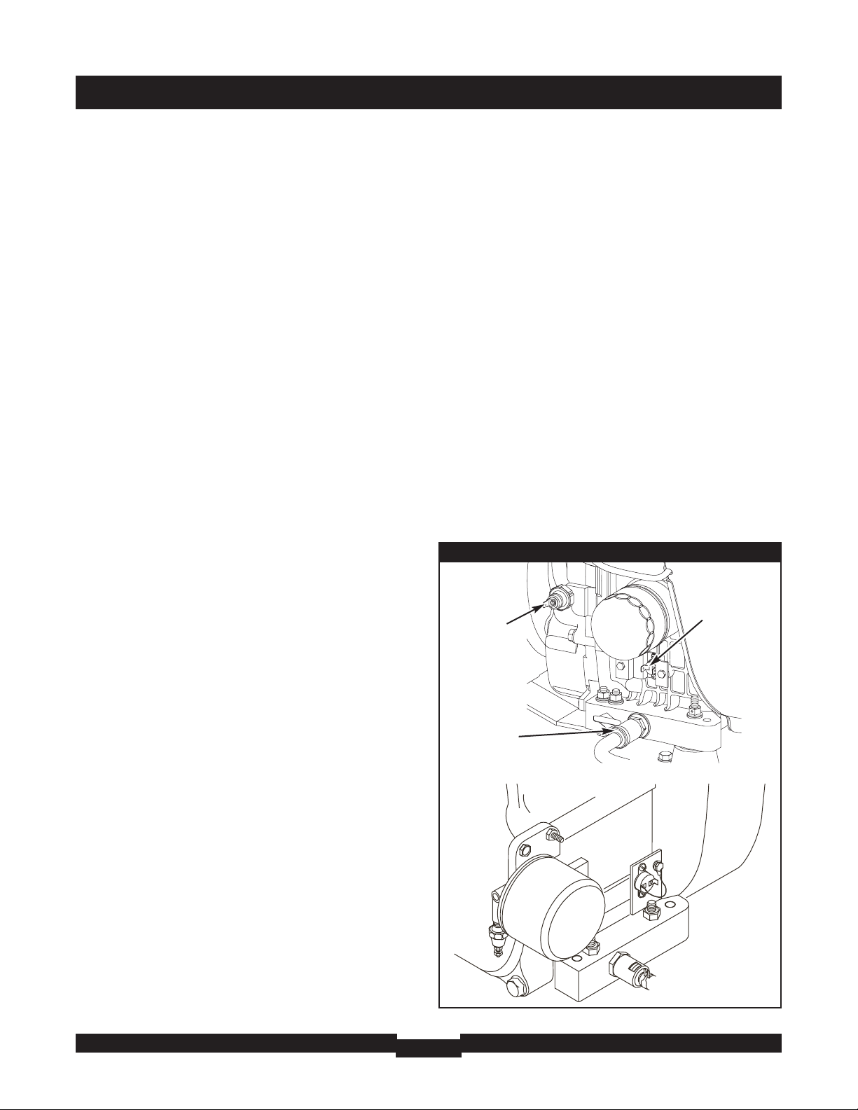
Low Oil Pressure
This fault is indicated by fault code FC_2 and two blinks on
the LED indicator. The unit is equipped with an oil pressure
switch (Figure 4) using normally closed contacts that are
held open by engine oil pressure during operation. Should oil
pressure drop below the 8 psi range, switch contacts close
and the engine is shut down.
Figure 4 — Low Oil Pressure & High Temp. Switches
High
Temperature
Switch
Oil Drain
Fitting
Oil
Pressure
Switch
Page 16

MAINTENANCE
16
To remedy the low oil pressure condition, add the
recommended oil to the FULL mark on the dipstick.
If low oil pressure condition still exists, engine will start, then
shut down after about 20 seconds and diagnostic LED will
flash. In this case, contact an authorized service facility.
Low Voltage (Generator)
This fault is indicated by fault code FC_3 and three blinks on
the LED indicator. This condition is caused by a restriction in
the fuel flow, a broken or disconnected signal lead, a failed
alternator winding, the control panel circuit breaker is open,
or Home Generator System is overloaded.
To remedy the problem, contact your local service center.
Engine Fail To Start
This fault is indicated by fault code FC_4 and four blinks on
the LED indicator. This feature prevents the generator from
damaging itself if it continually attempts to start in spite of
another problem, such as no fuel supply. Each time the
system is directed to start, the unit will crank for 10 seconds,
pause for 10 seconds, crank for 10 seconds, pause for
10 seconds, and repeat. If the system does not begin
producing electricity after approximately 2 minutes, the unit
will stop cranking and the LED will blink.
Check to make sure the generator’s main circuit breaker is in
the ON (closed) position in order for the sensing leads to
verify that the unit is running.
The most likely cause of this problem is no fuel supply.
Check the inside and outside fuel shut off valves to ensure
they are fully open. Other causes could be failed spark
plug(s), failed engine ignition, or the engine air filter is
clogged. You may need to contact your installer for
assistance if you can’t remedy these problems.
Low Frequency
This fault is indicated by fault code FC_5 and five blinks on
the LED indicator. This feature protects devices connected to
the transfer switch by shutting the generator down if the
engine runs slower than the preset limit.
• If the generator output frequency is below 55 Hz for three
seconds, the generator will shut down.
This condition is caused by a failed engine governor or by
excessive loads on the generator. To remedy the problem,
you may need to contact your installer or local service center
for assistance.
Engine Overspeed
This fault is indicated by fault code FC_6 and six blinks on
the LED indicator. This feature protects devices connected to
the transfer switch by shutting the generator down if the
engine happens to run faster than the preset limit. The
overspeed fault is detected as follows:
• If the generator output frequency is 65-70 Hz, after three
seconds, the generator will shut down.
• If the generator output frequency is greater than 70 Hz, the
generator will shut down instantly.
This condition is caused by a failed engine governor. To
remedy the problem, you should contact your installer or
local service center for assistance.
Oil Temperature High
This fault is indicated by fault code FC_7 and seven blinks on
the LED indicator. The contacts of the temperature switch
(Figure 4) are normally open. If the engine oil temperature
exceeds approximately 140°C (284°F), the fault is detected
and the engine shuts down.
Common causes for this condition include running the unit
with all access doors removed, obstructed air inlet or exhaust
port, low oil level, or debris in the engine cylinder cooling
fins.
To resolve the problem, remove any accumulated debris and
obstructions and let the engine cool down. Ensure that the
Oil Service door and/or the Control Panel door is installed
whenever the unit is running.
Transfer Switch Fault
This fault is indicated by fault code FC_8 and eight blinks on
the LED indicator (if transfer switch is equipped with fault
detection).
To remedy the problem, you should contact your installer or
local service center for assistance.
Page 17
MAINTENANCE
17
GENERATOR MAINTENANCE
The generator warranty does not cover items that have been
subjected to operator abuse or neglect. To receive full value
from the warranty, the operator must maintain the system as
instructed in the engine operator’s manual.
All adjustments should be made at least once each season.
Follow the requirements in the engine operator’s manual.
Generator maintenance consists of keeping the unit clean.
Operate the unit in an environment where it will not be
exposed to excessive dust, dirt, moisture or any corrosive
vapors. Cooling air louvers on the enclosure must not
become clogged with snow, leaves, or any other foreign
material.
Check the cleanliness of the unit frequently and clean when
dust, dirt, oil, moisture or other foreign substances are
visible on its exterior/interior surface.
NOTE: DO NOT use direct spray from a garden hose to clean
generator. Water can enter the engine and generator and
cause problems.
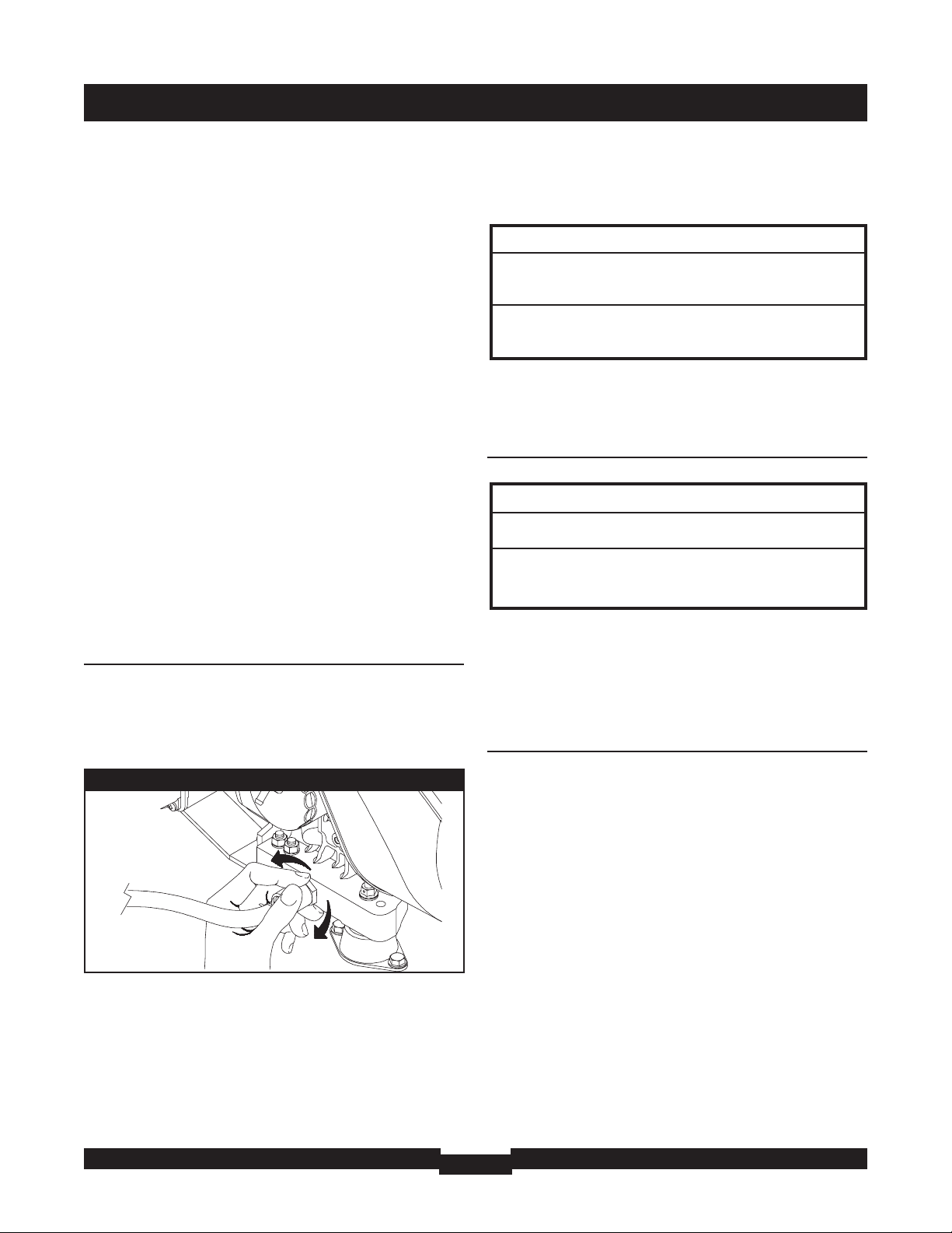
Changing Engine Oil
• Place the oil drain tube into an approved container.
• Push in and rotate the oil drain fitting 1/4 turn
counterclockwise. Slowly pull outward until oil starts
draining (Figure 5). DO NOT pull the oil drain fitting off the
engine.
• When the oil has drained, push the oil drain fitting in and
rotate 1/4 turn clockwise until it locks in place.
• Slide the oil drain tube up into the clamp on the generator.
To fill your engine with oil:
• Follow the synthetic oil grade recommendation and oil fill
instructions given in the engine operator’s manual.
To Clean the Generator
• Use a damp cloth to wipe exterior surfaces clean.
• Use a soft, bristle brush to loosen caked on dirt, oil, etc.
• Use a vacuum cleaner to pick up loose dirt and debris.
• Use low pressure air (not to exceed 25 psi) to blow away dirt.
Inspect cooling air slots and openings on the generator. These
openings must be kept clean and unobstructed.
When Calling the Factory
You must have the following information at hand if it is
necessary to contact a local service center regarding service
or repair of this unit:
1. Obtain the unit Model Number and Serial Number from
the unit data decal. See “Know Your Home Generator
System” diagram for location.
2. Obtain the engine Model/Type/Code numbers from the
engine label. See “Know Your Home Generator System”
diagram for location. Please note that the model number
may vary slightly from that presented herein.
STORAGE
The Briggs & Stratton Home Generator System is designed
for continuous backup operational duty. As such, there is no
need to take any storage precautions. However, if it becomes
necessary to take the system out of service for an extended
period, call Briggs and Stratton Technical Services at
1-800-743-4115, between 8:00 AM and 5:00 PM CT for
specific recommendations.
Figure 5 — Oil Drain Fitting
NOTICE
Any attempt to crank or start the engine before it has been
properly serviced with the recommended oil will result in
equipment failure.
• Refer to engine manual for oil fill information.
• Damage to equipment resulting from failure to follow this
instruction will void warranty.
NOTICE
Improper treatment of generator can damage it and
shorten its life.
• DO NOT expose generator to excessive moisture, dust, dirt, or
corrosive vapors.
• DO NOT insert any objects through cooling slots.
Page 18

TROUBLESHOOTING
18
TROUBLESHOOTING
Problem Cause Correction
Engine is running, but no AC output is
available.
1. Circuit breaker open or defective.
2. Fault in generator.
3. Poor wiring connections or
defective transfer switch.
1. Reset or replace circuit breaker.
2. Contact local service facility.
3. Check and repair.
Engine runs good at no-load but "bogs
down" when loads are connected.
1. Short circuit in a connected load.
2. Generator is overloaded.
3. Shorted generator circuit.
4. Fuel Pressure is incorrect.
5. Natural gas fuel mixture is
incorrect.
1. Disconnect shorted electrical load.
2. See "Essential Circuits".
3. Contact local service facility.
4. See "The Gaseous Fuel System" in
the Installation Manual.
5. See "The Gaseous Fuel System" in
the Installation Manual.
Engine will not start; or starts and runs
rough.
1. 15 Amp fuse missing or blown.
2. Out of fuel.
3. Failed battery.
1. Install (new) 15 Amp fuse. See
“Know Your System Control Panel”.
2. Open fuel valve(s); check propane
tank.
3. Replace battery.
Engine shuts down during operation.
1. Out of fuel.
2. Fault indicator blinking.
1. Check fuel valves, fill propane tank.
2. Count blinks and refer to "Fault
Detection System".
Loss of power on essential circuits.
1. Generator circuit breaker is open.
2. Transfer switch problems.
1. Reset circuit breaker.
2. See the transfer switch manual.
Page 19

The warranty period begins on the date of purchase by the first retail consumer or commercial end user, and continues for the period
of time stated in the table above. “Consumer use" means personal residential household use by a retail consumer. “Commercial use"
means all other uses, including use for commercial, income producing or rental purposes. Once equipment has experienced
commercial use, it shall thereafter be considered as commercial use for purposes of this warranty.
NO WARRANTY REGISTRATION IS NECESSARY TO OBTAIN WARRANTY ON BRIGGS & STRATTON PRODUCTS. SAVE YOUR
PROOF OF PURCHASE RECEIPT. IF YOU DO NOT PROVIDE PROOF OF THE INITIAL PURCHASE DATE AT THE TIME
WARRANTY SERVICE IS REQUESTED, THE MANUFACTURING DATE OF THE PRODUCT WILL BE USED TO DETERMINE THE
WARRANTY PERIOD.
An e
xtended fourth year of Consumer Use warranty for the engine and alternator is available by completing the customer registration
card and the installation checklist and returning both to Briggs & Stratton Power Products, LLC.
ABOUT YOUR WARRANTY
We welcome warranty repair and apologize to you for being inconvenienced. Any Authorized Service Dealer may perform warranty
repairs. Most warranty repairs are handled routinely, but sometimes requests for warranty service may not be appropriate. For
example, warranty service would not apply if equipment damage occurred because of misuse, lack of routine maintenance, shipping,
handling, warehousing or improper installation. Similarly, the warranty is void if the manufacturing date or the serial number on the
equipment has been removed or the equipment has been altered or modified. During the warranty period, the Authorized Service
Dealer, at its option, will repair or replace any part that, upon examination, is found to be defective under normal use and service.
This warranty will not cover the following repairs and equipment:
• Normal Wear: Outdoor Power Equipment and engines, like all mechanical devices, needs periodic parts and service to
perform well. This warranty does not cover repair when normal use has exhausted the life of a part or the equipment.
• Installation and Maintenance: This warranty does not apply to equipment or parts that have been subjected to improper or
unauthorized installation or alteration and modification, misuse, negligence, accident, overloading, overspeeding, improper
maintenance, repair or storage so as, in our judgment, to adversely affect its performance and reliability. This warranty also
does not cover normal maintenance such as adjustments, fuel system cleaning and obstruction (due to chemical, dirt, carbon,
lime, and so forth).
• other Exclusions: This warranty excludes wear items such as oil gauges, o-rings, filters, fuses, or spark plugs, etc., or damage
or malfunctions resulting from accidents, abuse, modifications, alterations, or improper servicing or freezing or chemical
deterioration. Accessory parts are excluded from the product warranty. This warranty excludes failures due to acts of God and
other force majeure events beyond the manufacturers control. Also excluded is used, reconditioned, and demonstration
equipment; equipment used for prime power in place of utility power and equipment used in life support applications.
198181-E,
Rev. B, 7/14/2006
BRIGGS & STRATTON POWER PRODUCTS GROUP, LLC
JEFFERSON, WI, USA
Effective September 1, 2005 replaces all undated Warranties and all Warranties dated before September 1, 2005
LIMITED WARRANTY
Briggs & Stratton Power Products Group, LLC will repair or replace, free of charge, any part(s) of the equipment that is defective
in material or workmanship or both. Transportation charges on product submitted for repair or replacement under this warranty
must be borne by purchaser.This warranty is effective for the time periods and subject to the conditions stated below. For
warranty service, find the nearest Authorized Service Dealer in our dealer locator map at BRIGGSandSTRATTON.com.
THERE IS NO OTHER EXPRESS WARRANTY. IMPLIED WARRANTIES, INCLUDING THOSE OF MERCHANTABILITY AND
FITNESS FOR A PARTICULAR PURPOSE, ARE LIMITED TO ONE YEAR FROM PURCHASE, OR TO THE EXTENT
PERMITTED BY LAW. ANY AND ALL IMPLIED WARRANTIES ARE EXCLUDED. LIABILITY FOR INCIDENTAL OR
CONSEQUENTIAL DAMAGES ARE EXCLUDED TO THE EXTENT EXCLUSION IS PERMITTED BY LAW. Some states or
countries do not allow limitations on how long an implied warranty lasts, and some states or countries do not allow the exclusion
or limitation of incidental or consequential damages, so the above limitation and exclusion may not apply to you.This warranty
gives you specific legal rights and you may also have other rights which vary from state to state or country to country.
3 years or 1500 Hours, whichever comes first
None
Consumer Use
Commercial Use
BRIGGS & STRATTON POWER PRODUCTS GROUP, LLC 12KW AND 15KW HOME GENERATOR OWNER WARRANTY POLICY
WARRANTY PERIOD
Page 20

REFERENCIA
20
TABLA DE CONTENIDO. . . . . . . . . . . . . . . . . . . . . . . . . . . . . . . . . 20
REGLAS DE SEGURIDAD. . . . . . . . . . . . . . . . . . . . . . . . . . . . . 21-23
INTRODUCCIÓN . . . . . . . . . . . . . . . . . . . . . . . . . . . . . . . . . . . . . . 24
Asistencia para la Instalación . . . . . . . . . . . . . . . . . . . . . . . . 24
Para el Propietario Doméstico . . . . . . . . . . . . . . . . . . . 24
Para el Agente de Ventas/Contratista . . . . . . . . . . . . . . 24
ORIENTACIÓN PARA EL PROPIETARIO . . . . . . . . . . . . . . . . . . . . 24
Factores Relacionados con el Combustible. . . . . . . . . . . . . . 25
Disminución de la Potencia a Temperaturas Elevadas o en
Lugares Altos . . . . . . . . . . . . . . . . . . . . . . . . 25
Ubicación del Generador. . . . . . . . . . . . . . . . . . . . . . . . . . . . 25
Distancias Desde el Generador . . . . . . . . . . . . . . . . . . . . 25-26
Circuitos Fundamentales. . . . . . . . . . . . . . . . . . . . . . . . . . . . 26
Selección de los Circuitos Fundamentales . . . . . . . . . . 27
DESEMPAQUE. . . . . . . . . . . . . . . . . . . . . . . . . . . . . . . . . . . . . . . . 27
Inspección al Momento de la Entrega. . . . . . . . . . . . . . . . . . 27
Contenido de la Caja . . . . . . . . . . . . . . . . . . . . . . . . . . . . . . . 27
CONOZCA SU GENERADOR DOMÉSTICO. . . . . . . . . . . . . . . . . . . 28
CONOZCA EL PANEL DE CONTROL DEL SISTEMA. . . . . . . . . . . . 29
Puertas de Acceso . . . . . . . . . . . . . . . . . . . . . . . . . . . . . . . . 30
Para Retirar una Puerta de Acceso . . . . . . . . . . . . . . . . 30
Para Instalar una Puerta de Acceso . . . . . . . . . . . . . . . 30
ANTES DEL ARRANQUE INICIAL . . . . . . . . . . . . . . . . . . . . . . . . . 31
Aceite de Motor. . . . . . . . . . . . . . . . . . . . . . . . . . . . . . . . . . . 31
Consideraciones Sobre el Aceite. . . . . . . . . . . . . . . . . . 31
Conexión de la Batería . . . . . . . . . . . . . . . . . . . . . . . . . . . . . 31
Sistema de Combustible Gaseoso. . . . . . . . . . . . . . . . . . . . . 31
OPERACIÓN AUTOMÁTICA . . . . . . . . . . . . . . . . . . . . . . . . . . . . . . 32
Verificación de la Operación Automática. . . . . . . . . . . . . . . . 32
Paro del Sistema. . . . . . . . . . . . . . . . . . . . . . . . . . . . . . . . . . 32
Configuración del Temporizador de Práctica. . . . . . . . . . . . . 32
SISTEMA DE DETECCIÓN DE FALLAS . . . . . . . . . . . . . . . . . . . . . 33
Restablecimiento del Sistema de Detección de Fallas. . 33
No se Enciende el LED - Batería Descargada . . . . . . . . 33
Baja Tensión de la Batería . . . . . . . . . . . . . . . . . . . . . . . 33
Baja Presión de Aceite. . . . . . . . . . . . . . . . . . . . . . . 33-34
Baja Tensión . . . . . . . . . . . . . . . . . . . . . . . . . . . . . . . . . 34
El Motor no Arranca . . . . . . . . . . . . . . . . . . . . . . . . . . . 34
Baja Frecuencia . . . . . . . . . . . . . . . . . . . . . . . . . . . . . . . 34
Sobrevelocidad del Motor . . . . . . . . . . . . . . . . . . . . . . . 34
Alta Temperatura del Aceite . . . . . . . . . . . . . . . . . . . . . 34
MANTENIMIENTO DEL GENERADOR . . . . . . . . . . . . . . . . . . . . . . 35
Cambio del Aceite del Motor. . . . . . . . . . . . . . . . . . . . . . . . . 35
Para Limpiar el Generador . . . . . . . . . . . . . . . . . . . . . . . . . . 35
Si Llama a la Fábrica. . . . . . . . . . . . . . . . . . . . . . . . . . . . . . . 35
ALMACENAMIENTO . . . . . . . . . . . . . . . . . . . . . . . . . . . . . . . . . . . 35
REPARACION DE AVERIAS. . . . . . . . . . . . . . . . . . . . . . . . . . . . . . 36
GARANTÍA. . . . . . . . . . . . . . . . . . . . . . . . . . . . . . . . . . . . . . . . . . . 37
TABLA DE CONTENIDO
Page 21

REGLAS DE SEGURIDAD
21
INSTRUCCIONES IMPORTANTES DE
SEGURIDAD
El símbolo de alerta de seguridad ( ) es usado con una palabra
(PELIGRO, ADVERTENCIA, PRECAUCIÓN), un mensaje por escrito o
una ilustración, para alertarlo acerca de cualquier situación de
peligro que pueda existir. PELIGRO indica un riesgo el cual, si no se
evita, causará la muerte o una herida grave. ADVERTENCIA indica
un riesgo el cual, si no se evita, puede causar la muerte o una
herida grave. PRECAUCIÓN indica un riesgo, el cual, si no se evita,
puede causar heridas menores o moderadas. AVISO indica una
situación que podría resultar en el daño del equipo. Siga los
mensajes de seguridad para evitar o reducir los riesgos de heridas e
inclusive la muerte.
El fabricante no puede prever todas las posibles circunstancias que
pueden implicar riesgos. Por lo tanto, las advertencias que aparecen
en este manual y las etiquetas y calcomanías adheridas a la unidad
no incluyen todas las posibilidades. Si aplica un procedimiento,
método de trabajo o técnica de operación no recomendada
específicamente por el fabricante, debe estar seguro de que se trata
de una práctica segura para usted y para otras personas. También
debe asegurarse de que el procedimiento, método de trabajo o
técnica de operación que elija, no haga que el generador se torne
inseguro.
NOTA: El generador viene equipado con un silenciador del escape
con amortiguador de chispas. El operador o el propietario debe
mantener el amortiguador de chispas en perfectas condiciones de
funcionamiento. En el estado de California, el amortiguador de
chispas es un elemento requerido por la ley (Sección 4442 del
California Public Resources Code). Otros estados pueden tener
leyes similares. En los territorios federales se aplican las leyes
federales.
Símbolos de Peligro y Significados
CONSERVE ESTAS INSTRUCCIONES
Page 22

REGLAS DE SEGURIDAD
22
ADVERTENCIA
Los generadores producen un voltaje muy poderoso.
Si no hace tierra apropiadamente con un generador,
puede hacer que ocurra un electrocutamiento.
Si no aísla el generador de utilidades de energía,
puede hacer que los trabajadores de electricidad
sufran heridas graves e inclusive la muerte, debido a
la retroalimentación de la energía eléctrica.
• Cuando use un generador como poder de energía auxiliar, notifique a la
compañía de utilidades.
• NO toque los alambres pelados o receptáculos.
• NO use un generador con cables eléctricos que estén malgastados,
rotos, pelados o dañados de cualquier forma.
• NO maneje el generador o cables eléctricos mientras esté parado en
agua, descalzo o cuando las manos y los pies estén mojados.
• Si fuera necesario realizar trabajos en cercanías de la unidad mientras
está en funcionamiento, párese sobre una superficie seca y aislada para
reducir los riesgos de una descarga.
• NO permita que personas descalificadas o niños operen o sirvan al
generador.
• En caso de que se produzca un accidente causado por una descarga
eléctrica, cierre inmediatamente la fuente de energía eléctrica y contacta
administración local. Evite el contacto directo con la víctima.
• A pesar del diseño seguro del sistema de generador de doméstico, si se
opera este equipo en forma imprudente, si no se cumple con el
mantenimiento o si se actúa con descuido, se pueden producir lesiones
o la muerte.
• Permanezca siempre alerta cuando trabaje con este equipo. NUNCA
trabaje con este equipo si se siente cansado física o mentalmente.
• Antes de realizar cualquier tarea de mantenimiento en el generador,
desconecte primero el cable de la batería marcado como NEGATIVE, NEG
o (-). Cuando haya terminado, vuelva a conectar el cable en último lugar.
• Una vez que el sistema de generador de doméstico está instalado, el
generador puede arrancar manualmente sin ninguna advertencia cada
vez que se produce una falla en el suministro de electricidad. Para evitar
posibles lesiones, siempre fije el conmutador del sistema en OFF, Y retire
el fusible de 15 Amperios ANTES de realizar trabajos en el equipo.
ADVERTENCIA
El Gas Natural y el Propano son extremadamente
inflamables y explosivos.
El fuego o una explosión pueden causar quemaduras
severas e inclusive la muerte.
• Instale el sistema de suministro de combustible de acuerdo con los
códigos de gas combustible que correspondan.
• Antes de poner en servicio el sistema de generador de doméstico, se
deben purgar las líneas del sistema de combustible y se debe probar si
presentan pérdidas.
• Una vez instalado el sistema, se lo debe inspeccionar en forma periódica.
• NO se debe permitir que se produzca ninguna pérdida.
• NO haga funcionar el motor si se percibe olor a combustible o si existe
alguna otra fuente de ignición.
• NO fume cerca del generador. Limpie en forma inmediata cualquier
derrame de aceite. Asegúrese de no dejar materiales combustibles en el
compartimiento del generador. Mantenga el área próxima al generador
limpia y libre de desperdicios.
ADVERTENCIA
El contacto con la zona del silenciador puede producir
quemaduras graves.
Los gases y el calor de escape pueden inflamar los
materiales combustibles y las estructuras y provocar
un incendio.
• NO toque las superficies calientes y evite los gases del escape a alta
temperatura.
• Permita que el equipo se enfríe antes de tocarlo.
• NO instale el generador a menos de 1,5 metros (5 pies) de todo material
combustible o estructura con muros combustibles cuya resistencia al
fuego sea inferior a una hora.
• Deje un espacio mínimo de 91 cm (3 pies) alrededor del generador,
incluida la parte superior.
• El Código de Normativa Federal (CFR, Título 36: Parques, Bosques y
Propiedad Pública) obliga a instalar una pantalla apagachispas en los
equipos con motor de combustión interno y a mantenerla en buenas
condiciones de funcionamiento, conforme a la norma 5100-1C (o
posterior) del Servicio Forestal de la USDA. En el Estado de California, la
ley exige el uso de una pantalla apagachispas (Sección 4442 del Código
de Recursos Públicos de California). En otros estados puede haber leyes
similares en vigor.
Page 23

REGLAS DE SEGURIDAD
23
PRECAUCIÓN
Las velocidades de operación en exceso, aumentan los riesgos
de heridas y daños al generador.
Las velocidades bajan en exceso, imponen una carga muy
pesada.
• NO cambie ninguna velocidad determinada. El generador suministra una
frecuencia y un voltaje calificado cuando funciona a una velocidad
determinada.
• NO modifique al generador en ninguna forma.
AVISO
El tratamiento inadecuado del generador puede dañarlo y acortar
su vida productiva.
• Use el generador solamente con la finalidad para el cual fue diseñado.
• Si usted tiene alguna pregunta acerca de las finalidades de uso del
generador, pregúntele a su concesionario o contacte a Briggs and
Stratton.
• Opere el generador solamente en superficies niveladas.
• Para la correcta operación del generador es fundamental contar con
ventilación y una circulación de aire de refrigeración adecuada y que no
sufra obstrucciones.
• La puerta de servicio del aceite o la del panel de control deben estar
instaladas siempre que la unidad esté en funcionamiento.
• NO exponga al generador a una humedad excesiva, polvo, suciedad o
vapores corrosivos.
• A pesar del diseño seguro del Generador Doméstico, si se opera este
equipo en forma imprudente, si no se cumple con el mantenimiento o
si se actúa con descuido, se pueden producir lesiones o la muerte.
• Permanezca siempre alerta cuando trabaje con este equipo. NUNCA
trabaje con este equipo si se siente cansado física o mentalmente.
• NUNCA encienda el motor si el filtro de aire o su cubierta han sido
retirados.
• NO inserte cualquier objeto a través de las ranuras de enfriamiento.
• NUNCA utilice el generador ni ninguna de sus piezas como escalera. Si
se sube sobre la unidad, sus piezas se pueden ver sobreexigidas y
pueden romperse. Esto puede dar como resultado condiciones de
operación peligrosas como consecuencias de la fuga de gases del
escape, pérdida de combustible, pérdida de aceite, etc.
• Si los aparatos conectados se sobrecalientan, apáguelos y
desconéctelos del generador.
• Apague el generador si:
-Se pierde la salida eléctrica;
-El equipo produce chispas, humo o emite llamas;
-La unidad vibra de una manera excesiva.
ADVERTENCIA
El arrancador y otras piezas que rotan pueden enredar
las manos, el pelo, la ropa, o los accesorios.
• NUNCA utilice la generador sin sus carcasas o tapas de protección.
• NO use ropa suelta, joyas o elementos que puedan quedar atrapados en
el arranque o en otras partes rotatorias.
• Ate para arriba el pelo largo y quite la joyería.
PRECAUCIÓN
Instala el fusible se puede producir el arranque del
motor.
• Tenga en cuenta que el fusible de 15 Amperios ha sido retirado del panel
de control para realizar el envío.
• NO instale este fusible hasta que no se hayan completado e
inspeccionado todas las conexiones de cables y tuberías.
AVISO
El sobrepasar la capacidad del amperaje y vataje del generador,
puede dañar al generador y los aparatos eléctricos conectados
al mismo.
• Vea "Circuitos Fundamentales".
• Encienda su generador y deje que el motor se estabilice antes de
conectar las cargas eléctricas.
Page 24

INSTALACIÓN
24
CONSERVE ESTAS INSTRUCCIONES
Este manual contiene instrucciones importantes que se deben
seguir durante la instalación y el mantenimiento del generador y de
la batería.
INTRODUCCIÓN
Muchas gracias por comprar un generador de reserva doméstico
(HGS) Briggs & Stratton. Este producto está pensado para utilizarlo
como un sistema de reserva doméstico opcional que proporciona
una fuente alternativa de energía eléctrica con capacidad para
alimentar cargas tales como sistemas de calefacción y refrigeración
y sistemas de comunicaciones, que cuando dejan de funcionar a
causa de una interrupción de la alimentación eléctrica de la red
pueden producir incomodidades o problemas. Este producto no
pertenece a la categoría de reserva de emergencia según lo definido
por la norma NFPA 70 (NEC).
Briggs and Stratton ha hecho todo lo posible para lograr una
instalación segura, eficiente y rentable. Como cada instalación es
única, es imposible conocer e informar acerca de todos los
procedimientos y métodos mediante los cuales se puede realizar la
instalación. Tampoco es posible conocer los riesgos o resultados
potenciales de cada método o procedimiento. Por todo lo expuesto,
La instalación de los Sistemas de Generadores Domésticos (HGS)
debe estar a cargo de contratistas especializados en electricidad
y plomería, sin excepciones. Las instalaciones deben cumplir
estrictamente con todos los códigos, regulaciones y normas
industriales aplicables.
El Generador Doméstico Briggs & Stratton incluye este "Manual del
Operario" y un "Manual de Instalación" separado. Estos son dos
documentos muy importantes que el propietario debe conservar una
vez finalizada la instalación.
Asistencia para la instalación
Para el Propietario Doméstico:
Para que pueda tomar decisiones fundamentadas y lograr una
comunicación efectiva con el o los contratistas de instalación.
Lea y comprenda la sección de este manual denominada
Orientación para el Propietario ANTES
de contratar o iniciar la
instalación de su Generador Doméstico (HGS).
Para coordinar y organizar una instalación adecuada, consulte al
comercio en el cual adquirió su Generador Doméstico Briggs &
Stratton, a su agente de ventas o a la compañía proveedora de
electricidad.
La garantía del HGS se ANULA
si la instalación del sistema no está a
cargo de profesionales especializados en electricidad y plomería
debidamente certificados y matriculados.
Para el Agente de Ventas/Contratista que Realiza la instalación:
Para la mayoría de las aplicaciones, el Manual de Instalación
contiene toda la información necesaria para instalar y arrancar
adecuadamente el Generador Doméstico. En este Manual del
Operario se describe la selección de los circuitos
fundamentales, la operación de rutina y los procedimientos de
mantenimiento que debe llevar a cabo el propietario.
Si necesita más información, llame al 1-800-743-4115, entre las
8:00 AM y las 5:00 PM hora del centro.
El sistema de control de emisiones para este generador está
garantizado para las normas establecidas por la Agencia de
Protección Ambiental de EE.UU. y por el Consejo de Recursos del
Aire de California (CARB).
ORIENTACIÓN PARA EL PROPIETARIO
En esta sección se brinda al propietario del Generador Doméstico la
información necesaria para lograr la instalación más rentable y
satisfactoria posible.
Las ilustraciones se aplican a circunstancias típicas y están
destinadas a que usted se familiarice con las opciones de
instalación disponibles con su Generador Doméstico. El
entendimiento completo de dichas opciones permite tener un
control fundamental sobre el costo de la instalación y garantiza su
seguridad y satisfacción final.
Los códigos locales, la apariencia, los niveles de ruido, los tipos de
combustible y las distancias son los factores fundamentales a tener
en cuenta cuando se realiza la negociación con el profesional que
tendrá a su cargo la instalación. Recuerde que a medida que la
distancia del servicio de electricidad existente y del suministro de
combustible aumenta, se debe tener en cuenta una compensación
igual en los materiales de cableado y tuberías. Esto es necesario
para cumplir con los códigos locales y solucionar caídas en la
tensión eléctrica y caídas en la presión del combustible gaseoso.
Los factores antes mencionados tendrán un efecto directo sobre
el precio general de la instalación del Generador Doméstico.
NOTA: En algunas áreas, es posible que deba obtener permisos
especiales para las instalaciones eléctricas del Generador
Doméstico, permisos de construcción para la instalación de las
líneas de gas y permisos para niveles de ruido admisibles. El
instalador debe verificar los códigos locales Y obtener los permisos
correspondientes antes de instalar el sistema.
Page 25

INSTALACIÓN
25
Factores Relacionados con el Combustible
Un tema importante que afecta a toda la instalación es el tipo de
combustible utilizado por el Generador Doméstico. El sistema fue
ajustado y probado en la fábrica utilizando gas natural como
combustible. También se puede usar propano líquido (LP) como
combustible (consulte el Manual de Instalación).
Si bien existen algunos factores específicos inherentes a cada uno
de estos combustibles, su ubicación y la duración de las posibles
interrupciones del servicio provisto por la compañía proveedora de
electricidad deben servir de guía para seleccionar el tipo de
combustible. Para instalaciones urbanas, la opción en cuanto al
combustible debería ser el gas natural (si está disponible). Para
instalaciones alejadas, es posible que un tanque de gas licuado de
petróleo (LP) sea lo más apto para sus necesidades.
Para el adecuado funcionamiento del motor, se recomienda seguir
estas pautas vinculadas con el combustible:
• Utilice combustible limpio y seco, libre de humedad o cualquier
otro material. Si se utilizan combustibles que no cumplan con
estos valores recomendados se pueden presentar problemas de
funcionamiento.
En motores preparados para funcionar a gas propano (LP), el
propano comercial de grado HD5 con un nivel de energía
combustible mínimo de 2500 BTU/pie cúbico con un contenido
de propileno máximo del 5% y un contenido de gas butano o
gases más pesados y un contenido mínimo de propano de 90%.
Disminución de la Potencia a Temperaturas Elevadas o en
Lugares Altos
La densidad del aire es menor en alturas elevadas, dando como
resultado una menor energía disponible del motor. Específicamente, la
potencia del motor disminuirá un 3.5% cada 1000 pies (300 metros)
por sobre el nivel del mar y un 1% cada 10° F (5.6°C) por encima de los
77°F (25°C). Tanto usted como el instalador deben tener en cuenta estos
factores cuando determinen la carga total del generador.
Ubicación del Generador
La ubicación física real de su generador de respaldo tiene un efecto
directo en:
1. La magnitud de las conexiones necesarias para entregar
combustible al generador.
2. La cantidad de cableado requerido para controlar y conectar su
generador.
NOTA: En el Manual de Instalación se analizan las pautas específicas
para la ubicación. Familiarícese con esa información y consulte al
instalador. Asegúrese de consultar de qué manera el predio o sitio
podría afectar los costos de instalación y el cumplimiento de las
normas y los códigos locales.
Ubicación del Generador de Reserva
Antes de aplicar estas pautas generales, consulte al propietario y
comuníquele cualquier factor técnico a tener en cuenta que pudiera
influir en sus decisiones y deseos.
Distancias Desde el Generador
Sitúe el generador en una zona bien ventilada que permita la
eliminación de los gases de escape mortales. NO instale el generador
en lugares en los que los gases de escape se puedan acumular o entrar
en un edificio que pueda estar ocupado. Asegúrese de que los gases de
escape no puedan entrar por ventanas, puertas, tomas de aire de
ventilación u otras aberturas en un espacio cerrado en el que puedan
acumularse (Figura 6). Tenga en cuenta los vientos y las corriente de
aire preponderantes cuando elija la ubicación del generador.
ADVERTENCIA
El Gas Natural y el Propano son extremadamente
inflamables y explosivos.
El fuego o una explosión pueden causar quemaduras
severas e inclusive la muerte.
• Este equipo cuenta con una válvula automática de seguridad de cierre
de combustible.
• NO haga funcionar el equipo si la válvula de cierre de combustible no
funciona o ha sido retirada.
ADVERTENCIA
Los gases y el calor de escape pueden inflamar los
materiales combustibles y las estructuras provocar un
incendio.
• NO instale el generador a menos de 1,5 metros (5 pies) de todo
material combustible o estructura con muros combustibles cuya
resistencia al fuego sea inferior a una hora.
• Deje un espacio mínimo de 91 cm (3 pies) alrededor del generador,
incluida la parte superior.
ADVERTENCIA
Al motor funcionar, se produce monóxido de carbono,
un gas inodoro y venenoso.
Respirar monóxido de carbono puede provocar dolor
de cabeza, fatiga, mareos, vómitos, confusión,
ataques, náuseas, desmayos o incluso la muerte.
• Opere el generador SOLAMENTE al aire libre.
• Instale una alarma de monóxido de carbono con batería cerca de los
dormitorios.
• Asegúrese de que los gases de escape no puedan entrar por ventanas,
puertas, tomas de aire de ventilación u otras aberturas en un espacio
cerrado en el que puedan acumularse.
Page 26

INSTALACIÓN
26
Pautas Generales para la Ubicación del Generador
• La unidad SÓLO debe instalarse en exteriores.
• Ubique la unidad en un lugar preparado, que sea plano y cuente
con sistemas de drenaje de agua.
• Instale la unidad en un lugar en el que el agua procedente de
bombas, canalizaciones de desagüe, canalones de tejado,
sistemas de irrigación o aspersores no pueda inundarla, mojar la
caja ni penetrar por las aberturas de entrada o salida de aire.
• Instale la unidad de forma que no dificulte ni afecte a servicios
tales como el teléfono, la electricidad, el suministro de
combustible, el aire acondicionado o el riego, incluidos los
servicios ocultos o subterráneos.
• Instale la unidad en un lugar donde las aberturas de entrada y
salida de aire no queden obstruidas por hojas, pasto, nieve, etc.
Si los vientos preponderantes ocasionan voladuras o arrastres,
es posible que deba construir un rompevientos para proteger la
unidad.
• Instale el generador lo más cerca posible del sistema de
transferencia de energía automático para reducir la longitud del
cableado y las canalizaciones.
• Instale el generador lo más cerca posible del suministro de
combustible para reducir la longitud de los caños.
IMPORTANTE: Es posible que las leyes o los códigos locales
regulen la distancia al suministro de combustible.
El generador de reserva se envía ya unido a su placa de montaje. A
menos que los códigos locales así lo soliciten, no es necesario
construir una losa de concreto.
Si los códigos locales exigen ese requisito, construya una losa de
concreto que tenga por lo menos 3 pulgadas (7.5 cm) de espesor y
que sea 6 pulgadas (15 cm) más larga y más ancha que la unidad.
Coloque la unidad sobre la losa utilizando pernos de anclaje para
albañilería de 14" de diámetro (como mínimo), que sean lo
suficientemente largos para soportar la unidad.
Circuitos Fundamentales
Como propietario de un Generador Doméstico, es importante que
usted pueda identificar claramente los circuitos de su edificio que
resultan "fundamentales" para usted. El Generador Doméstico viene
equipado con un conmutador de transferencia automático.
Es importante que el instalador comprenda cuáles son los circuitos
que usted desea incluir como "Circuitos Fundamentales". Dependiendo
de la potencia consumida por esos circuitos, la mayoría de ellos o
todos pueden pasar al Generador Doméstico por el tiempo que dure la
interrupción del servicio eléctrico normal.
La guía de referencia de potencias que se muestra en la Figura 7
puede ayudarle a tomar una decisión. En ella encontrará la potencia
utilizada por la mayoría de los dispositivos domésticos de uso
habitual. Utilice esa información como guía para seleccionar los
circuitos fundamentales. Analice esa información con el instalador y
consulte sobre cualquier factor técnico que pudiera tener algún
efecto sobre el costo de la instalación.
Dispositivo
Vatiaje de
operación
Aire acondicionador (12000 Btu)*
1700
Aire acondicionador (24000 Btu)*
3800
Aire acondicionador (40000 Btu)*
6000
Cargador de baterías (20 amperios)
500
Sierra circular (6-1/2")
entre 800 y 1000
Secadora de ropa (eléctrica)*
5750
Secadora de ropa (a gas)*
700
Lavadora de ropa*
1150
Cafetera
1750
Compresor (1 HP)*
2000
Compresor (1/2 HP)*
1400
Compresor (3/4 HP)*
1800
Tenacillas rizadoras
700
Deshumidificador*
650
Manta eléctrica
400
Cocina eléctrica (por elemento)
1500
Sartén eléctrica
1250
Freezer*
700
Ventilador de caldera (3/5 HP)*
875
Sistema de apertura de la puerta del
garaje*
entre 500 y 750
Secador de cabello
1200
Taladro de mano
entre 250 y 1100
Plancha
1200
Bomba de chorro*
800
Lamparilla de luz
100
Horno de microondas
entre 700 y 1000
Refrigerador de leche*
1100
Quemador de aceite en una caldera
300
Calefactor de ambientes a aceite
(140000 Btu)
400
Calefactor de ambientes a aceite
(30000 Btu)
150
Calefactor de ambientes a aceite
(85000 Btu)
225
Radio
entre 50 y 200
Refrigerador
700
Aparato para cocimiento lento
200
Bomba sumergible (1 HP)*
2000
Bomba sumergible (1/2 HP)*
1500
Bomba sumergible (1-1/2 HP)*
2800
Bomba de sumidero*
entre 800 y 1050
Sierra de banco (10")*
entre 1750 y 2000
Televisor
entre 200 y 500
Tostadora
entre 1000 y 1650
Figura 7 — Guía de Referencia de Potencia
*Considere tres (3) veces el vatiaje indicado para arrancar el dispositivo
Page 27

INSTALACIÓN
27
Selección de los Circuitos Fundamentales
Al seleccionar los circuitos fundamentales que pasarán a "Energía de
Respaldo", es importante que la suma de las cargas de los circuitos
combinados no supere la capacidad de potencia/corriente del
generador. Tenga en cuenta lo siguiente para facilitar la selección de
los circuitos fundamentales:
Sume la potencia total de todos los dispositivos eléctricos que
se van a conectar al mismo tiempo. Este total NO debe ser
mayor que la capacidad de vatiaje del generador.
La potencia nominal de la iluminación puede obtenerse
observando las lamparillas. La potencia nominal de las
herramientas, los electrodomésticos y los motores, por lo
general se puede encontrar en una placa de datos o en una
calcomanía adherida a cada dispositivo.
Si la potencia en vatios no figura en la placa de características
del aparato, herramienta o motor, multiplique los voltios por los
amperios para determinar los vatios (voltios x amperios =
vatios).
Algunos motores eléctricos (los del tipo de inducción) requieren
aproximadamente tres veces más vatios de potencia para
arrancar que la que utilizan mientras están en funcionamiento.
Esta sobrecarga dura sólo unos pocos segundos. Asegúrese de
tener en cuenta este elevado valor de potencia de arranque
cuando seleccione los dispositivos eléctricos que serán
energizados utilizando el Generador Doméstico.
• Considere los vatios necesarios para arrancar el motor
más grande.
• Agregue ese valor a los vatios totales necesarios para el
funcionamiento de todas las otras cargas conectadas.
El Generador Doméstico Briggs & Stratton respeta los siguientes
"valores nominales de energía de reserva fija":
El valor nominal de energía de reserva se aplica para
proporcionar energía de emergencia para el tiempo que dure la
interrupción del servicio de energía normal. No está disponible
la capacidad de sobrecarga para este valor nominal.
Estos valores nominales son aplicables a instalaciones
alimentadas por una fuente de energía eléctrica normal fiable.
Este valor nominal sólo es aplicable a cargas variables con un
factor de carga medio del 80% del valor nominal de reserva. El
valor nominal de reserva sólo es aplicable para la alimentación
eléctrica de reserva opcional cuando el grupo generador sirve
como reserva para la fuente de alimentación normal de la
compañía eléctrica.
Utilice la "Guía de Referencia de Potencia" provista y marque
aquellos circuitos que considere "críticos" o "fundamentales". Tanto
usted como el instalador deben tener en cuenta los rangos de
temperatura ambiente y de altitud por sobre el nivel del mar cuando
determinen la carga total del generador.
IMPORTANTE: Si utiliza el interruptor de transferencia de 100A o de
200A con el generador de reserva doméstico, deberá desconectar
todas las cargas eléctricas no esenciales. Si no se desconectan las
cargas no esenciales, el generador podría sobrecargarse, lo que
provocaría su parada. Algunos ejemplos de cargas no esenciales
son los siguientes:
• Bomba de la piscina
• Bañera con calefacción
• Calentadores eléctricos de bañera y / o piscina
• Acondicionadores de aire centrales
• Calentadores eléctricos de agua caliente
• Cocina y / u horno eléctrico
• Máquina de soldar por arco
• Calentadores eléctricos no esenciales
DESEMPAQUE
Remítase al Manual de Instalación para obtener instrucciones
detalladas de desempaque, si así lo desea.
Inspección al Momento de la Entrega
Luego de retirar la caja, inspeccione cuidadosamente el Generador
Doméstico para detectar cualquier daño que pudiera haber ocurrido
durante el traslado.
IMPORTANTE: Si en el momento de la entrega se detecta alguna
pérdida o daño, solicite a la persona o personas encargadas de la
entrega que dejen debida constancia en la nota de entrega y que
firmen debajo de la nota del consignador donde se informa acerca
de la pérdida o daño. Si la pérdida o el daño se detecta después de
la entrega, separe los materiales dañados y póngase en contacto
con el transportista para llevar a cabo los procedimientos de
reclamo. Las piezas perdidas o dañadas no están garantizadas.
Contenido de la Caja
El Generador Doméstico incluye lo siguiente:
• Sistema de generador de doméstico
• Placa de montaje fijada previamente
• Un tubo de enganche flexible
• Manual de instalación
• Manual del operario
• Manual ilustrado de listas de piezas
• Lista de verificación de la instalación
• Dos llaves para la puerta de acceso
• Cuatro tapones para los orificios de izamiento
• Tubo para la carga de aceite
• Un fusible de 15 Amperios de repuesto
• Toma bipolar - 240 V, doméstica
• Toma de 10 polos - Cables de detección y control
• Tapa de la admisión de aire del motor
• Tapa del alternador
• Equipo del LED de diagnóstico (rojo LED/placa/tornillos (2))
Page 28

CARACTERÍSTICAS Y CONTROLES
28
CONOZCA SU GENERADOR DOMÉSTICO DE RESERVA
Lea este manual del operario y las reglas de seguridad antes de operar su generador.
Compare las ilustraciones con su Generador para familiarizarse con las ubicaciones de los diferentes controles y ajustes. Conserve
este manual para referencias futuras.
Batería - La batería sellada de 12 Voltios de c.c. y 55 Amperios/h
proporciona la energía necesaria para arrancar el motor. La batería
recibe carga lenta y continua mientras el generador no está en
funcionamiento.
Calcomanía de Datos de la Unidad (situada en la base) -
Identifica a la unidad mediante un número de serie.
Depurador de Aire - Filtra el aire de entrada a medida que penetra
en el motor.
Etiqueta del Motor - Identifica el tipo y modelo del motor.
Filtro de Aceite - Filtra el aceite del motor para prolongar la vida útil
del sistema.
Fusible de 15 Amperios - Protege los circuitos de control de c.c.
del Generador Doméstico.
Manguera de Drenaje de Aceite - Provista para facilitar el cambio
de aceite.
Panel de Control - Se utiliza para distintas funciones de
mantenimiento, operación y prueba. Consulte la sección "CONOZCA
EL PANEL DE CONTROL DEL SISTEMA", en la página siguiente.
Salida del Escape - Silenciador de alto rendimiento que disminuye
los ruidos del motor para cumplir con los códigos necesarios para
zonas residenciales.
Tapa del Compartimiento de Aceite - Se debe retirar para llenar la
unidad con el aceite recomendado.
Varilla para Medir el Aceite - Se utiliza para controlar el nivel de
aceite del motor.
Page 29

CARACTERÍSTICAS Y CONTROLES
29
Conmutador de Cancelación Manual - Con el conmutador del
sistema en la posición AUTO, pulse en conmutador de cancelación
manual para poner en marcha el generador. Pulse de nuevo el
conmutador de cancelación manual para apagar el generador.
Conmutador del Sistema - Este dispositivo de dos posiciones es el
control más importante en el sistema. Se utiliza de la siguiente
manera:
• La posición "AUTO" es la posición normal funcionamiento. Si se
detecta una interrupción de la alimentación eléctrica de la red, el
sistema hace que arranque el generador. Cuando se restablece
la alimentación eléctrica de la red, el sistema espera a que se
estabilicen las temperaturas internas del motor, para el
generador y se pone en estado de espera para la próxima vez
que se interrumpa la alimentación eléctrica.
• La posición "OFF" hace que se pare el generador, impide el
arranque de la unidad y reinicializa cualquier fallo detectado.
Fusible de 15 Amperios - Protege los circuitos de control de c.c.
del Generador Doméstico. Si el fusible está "quemado" (fundido
abierto) o si se ha retirado, el motor no se puede arrancar ni
arrancar manualmente en forma lenta. Cambie el fusible por otro
idéntico: ATO de 15 A.
Herramienta de Servicio - SÓLO la debe utilizar el personal de
servicio debidamente cualificado.
Interruptor de Configuración de Práctica - Se utiliza para
configurar la hora y el día de la semana en que se inicia el ciclo de
práctica. El ciclo de práctica sólo se produce en el modo AUTO.
Interruptor de Potencia - Protege al sistema de condiciones de
cortocircuitos y otros excesos de corriente. Debe estar en la
posición ON para abastecer de energía al conmutador de
transferencia automático.
Pantalla Digital - Muestra el número total de horas de
funcionamiento del generador y los códigos de fallo. Se utiliza para
programar las tareas de mantenimiento y para resolver problemas
de funcionamiento del generador de reserva doméstico. Todas las
condiciones de fallo se describen en la sección “Sistema de
detección de fallos”.
CONOZCA EL PANEL DE CONTROL DEL SISTEMA
Compare esta ilustración del panel de control con su generador para familiarizarse con la ubicación de estos controles importantes:
Page 30

INSTALACIÓN
30
Puertas de Acceso
El Generador Doméstico está equipado con un compartimiento que
tiene tres puertas de acceso (Figura 8). Los nombres de las puertas
están relacionados con el componente importante ubicado detrás de
ellas. Comenzando por el lado que tiene la conexión para
combustible y siguiendo hacia la derecha, los nombres de las
puertas son:
• Puerta de Llenado de Aceite
• Puerta del Panel de Control
• Puerta de Vaciado de Aceite
Cada generador de reserva doméstico está equipado con dos llaves
idénticas que accionan los cerrojos de las puertas de acceso.
Para abrir una puerta de acceso:
1. Inserte la llave en la cerradura de la puerta de acceso que
desee abrir y gire un cuarto de vuelta hacia la izquierda.
2. Agarre el picaporte de la puerta y gire un cuarto de vuelta hacia
la izquierda para abrir. Retire la llave.
Para cerrar una puerta de acceso:
1. Cierre la puerta y gire su picaporte un cuarto de vuelta hacia la
derecha.
2. Inserte la llave en la cerradura de la puerta de acceso y gire un
cuarto de vuelta hacia la derecha. Retire la llave.
Page 31

INSTALACIÓN
31
ANTES DEL ARRANQUE INICIAL
Aceite de Motor
Este motor se envía desde la fábrica lleno con el aceite
recomendado. Antes de arrancar el motor, verifique el nivel de aceite
y asegúrese de que el motor haya recibido el mantenimiento que se
describe en la manual del motor.
Consideraciones Sobre el Aceite
El Generador Doméstico está equipado con un motor que ha
completado el proceso de funcionamiento previo en la fábrica y no
requiere el procedimiento tradicional de "entrada forzada".
A fin de proporcionar una mayor capacidad de "respaldo", el sistema
se llena con aceite sintético (API SJ/CF 5W-30W). Esto permite la
operación del sistema en un amplio rango de condiciones climáticas
y de temperatura.
NOTA: El hecho de utilizar aceite sintético NO modifica los intervalos
de cambio de aceite necesarios descritos más adelante en la
sección dedicada a mantenimiento en la manual del motor.
Conexión de la Batería
El generador de reserva doméstico se suministra con una batería
con regulación por válvulas de 12 V CC, 55 Ah. Es una batería
estanca de plomo-ácido recargable. La batería se suministra
instalada en la unidad y sus cables se conectan en fábrica. El fusible
de 15 A del generador se ha retirado para evitar el arranque de la
unidad durante el transporte.
NOTA: Estando la batería instalada y terminado todo el cableado
hasta el interruptor de transferencia y el generador de reserva
doméstico, al aplicar tensión de la red al interruptor automático de
transferencia con la unidad en modo AUTO, la batería recibe una
carga lenta y continua mientras el motor no está funcionando. El
cargador de carga lenta no se puede utilizar para recargar una
batería que esté totalmente descargada.
Sistema de Combustible Gaseoso
• Asegúrese de que todas las conexiones de la cañería de
combustible estén ceñidas, firmes y que no presenten pérdidas.
• Asegúrese de que todas las válvulas de cierre estén abiertas
(OPEN) y que la presión disponible sea la adecuada (ver el
manual de instalación).
AVISO
Cualquier intento para arancar el motor antes de haberle
proporcionado el mantenimiento apropiado con el aceite
recomendado, podría ocasionar la falla del motor.
• Consulte el manual del operario del motor para añadir al motor el aceite
y el combustible recomendado.
• El daño a la generador, resultado de la desatención a esta precaución,
no será cubierto por la garantía.
PRECAUCIÓN
Instala el fusible se puede producir el arranque del
motor.
• NO instale este fusible hasta que no se hayan completado e
inspeccionado todas las conexiones de cables y tuberías.
ADVERTENCIA
El Gas Natural y el Propano son extremadamente
inflamables y explosivos.
El fuego o una explosión pueden causar quemaduras
severas e inclusive la muerte.
• NO haga funcionar el motor si se percibe olor a combustible o si existe
alguna otra fuente de ignición.
• Si percibe olor a combustible gaseoso (gas natural o LP) cerca de la
unidad, cierre inmediatamente el suministro de gas al generador.
• Póngase en contacto con la compañía proveedora del servicio de gas o
con el instalador del sistema para obtener ayuda para determinar el
origen del olor.
Page 32

OPERACIÓN
32
OPERACIÓN AUTOMÁTICA
Para seleccionar la operación de transferencia automática, haga lo
siguiente:
1. Ponga el seccionador de servicio o el interruptor del cuadro de
distribución principal que alimenta tensión de la red al
interruptor de transferencia en la posición ON (cerrado).
2. Ponga el interruptor principal del generador en la posición ON.
3. Ponga el conmutador del sistema del generador en la posición
AUTO.
Verificación de la Operación Automática
Para verificar la correcta operación automática del sistema, proceda
de la siguiente manera:
1. Ponga en el seccionador de servicio o el interruptor del cuadro
de distribución principal que alimenta tensión al interruptor
automático de transferencia en la posición OFF.
El motor comenzará a dar vueltas y arrancará cuando descienda la
tensión de la red y transcurra el tiempo determinado por el
temporizador. Deje que el sistema realice la secuencia completa de
funcionamiento automático.
2. Con la salida del generador alimentando las cargas conectadas,
ponga el seccionador de servicio o el interruptor del cuadro de
distribución principal que alimenta tensión al interruptor
automático de transferencia en la posición ON.
3. El interruptor automático de transferencia transferirá de nuevo
las cargas a la red después de un tiempo de funcionamiento de
cinco minutos como mínimo, restableciéndose la alimentación
desde la red.
4. El generador seguirá funcionando durante un minuto más para
que se enfríe el motor y luego se parará.
NOTA: Si el generador no se para después de transcurrir diez minutos,
ponga el conmutador del sistema en la posición OFF y póngase en
contacto con el instalador o con el centro de servicio local.
De esta manera se completan los procedimientos de prueba de la
operación automática. El Generador Doméstico arrancará
automáticamente cuando se pierda la energía de la compañía
proveedora de electricidad y proporcionará energía al conmutador
de transferencia.
Paro del Sistema
Para desactivar el sistema de transferencia de energía para realizar
tareas de mantenimiento:
1. Fije el conmutador del sistema en la posición OFF.
2. Fije el interruptor de potencia principal del generador en la
posición ON.
3. La tensión de detección de la red está presente. Desconecte la
alimentación antes de proceder al servicio quitando los dos
fusibles de 2 A del interruptor de transferencia.
Configuración del Temporizador de Práctica
El Generador Doméstico está equipado con un temporizador de
práctica que arranca el sistema y lo prueba una vez cada siete días.
Durante este período de práctica, la unidad trabaja durante
aproximadamente 20 minutos y luego se apaga. Durante el ciclo de
práctica NO se produce la transferencia de cargas eléctricas (a
menos que se produzca un corte en el suministro de la compañía
proveedora de electricidad).
En el panel de control se encuentra un interruptor rotulado "Set
Exercise" (configurar práctica) (ilustrado en pagina 29). El día y la hora
específicos en que se presiona este interruptor se programa en la
memoria del panel de control. Esta fecha y esta hora se utilizan para
iniciar automáticamente el ciclo de práctica del sistema. El LED del
panel de control parpadeará hasta que se active la prueba.
Para llevar a cabo el procedimiento para configurar la práctica
(Set Exercise):
1. Elija el día y la hora en que desea que se realice la práctica del
Generador Doméstico.
2. Ese día y a esa hora
, pulse y mantenga pulsado el conmutador
“Set Exercise” (Preparar prueba) durante tres segundos.
NOTA: El LED parpadeará hasta que el conmutador se mantenga
pulsado tres segundos. A continuación, el LED se encenderá
durante cinco segundos y se apagará.
Por ejemplo, si presiona el interruptor "Set Exercise" el domingo a
las 10 de la mañana, la unidad realizará un ciclo de práctica el
próximo domingo a las 10 de la mañana.
NOTA: La función de configuración de práctica ("Set Exercise") sólo
funciona si la unidad se encuentra en el modo Automático y si se
cumple este procedimiento en forma estricta. El dispositivo de
prueba deberá rearmarse si el fusible de 15 A se cambia o retira o
si la batería de 12 V CC se desconecta.
Si desea cambiar el día y la hora en que se realiza la práctica de la
unidad, simplemente realice el procedimiento de configuración de
práctica ("Set Exercise") exactamente el día de la semana y a la hora
en que desea que se lleve a cabo.
PRECAUCIÓN
Con el interruptor en la posición AUTO, el motor
puede comenzar a dar vueltas y arrancar en cualquier
momento sin previo aviso. Este arranque automático
se produce normalmente cuando la tensión de la red
desciende por debajo de un nivel predeterminado o
durante el ciclo de prueba normal.
• Para evitar posibles lesiones que podrían suceder como consecuencia de
un arranque repentino, siempre fije el conmutador del sistema en OFF.
• Retire el fusible de 15 Amperios antes de realizar trabajos en el
generador, en el conmutador de transferencia o en lugares cercanos a
estos equipos.
Page 33

MANTENIMIENTO
33
SISTEMA DE DETECCIÓN DE FALLAS
Es posible que el generador deba funcionar durante períodos
prolongados sin la presencia de un operador. Por ese motivo, el
sistema está equipado con sensores que automáticamente detienen
el generador en caso de que se produzca una situación
potencialmente dañina, como por ejemplo una baja en la presión de
aceite, una elevada temperatura del aceite, sobrevelocidades y otras
condiciones.
El panel de control del generador incluye una pantalla digital que
muestra los códigos de fallo. Un indicador LED opcional situado
cómodamente en el interior parpadeará reproduciendo un patrón si
se detectan determinados problemas en el generador. El patrón se
repite con una breve pausa entre cada serie. El código de fallo que
se muestra en el panel de control y el número de parpadeos de la
placa de montaje indican el fallo detectado:
Código de fallo /
Parpadeos del LED Descripción de la Falla
FC_1 / 1 Baja tensión de la batería
FC_2 / 2 Baja presión de aceite
FC_3 / 3 Baja tensión
FC_4 / 4 El motor no arranca
FC_5 / 5 Baja frecuencia
FC_6 / 6 Sobrevelocidad del motor
FC_7 / 7 Alta temperatura del aceite
FC_8 / 8 Fallo del conectador
Restablecimiento del Sistema de Detección de Fallas
El operador debe restablecer el sistema de detección de fallas cada
vez que se activa. Para hacerlo, ponga el conmutador del sistema en
la posición OFF durante 30 segundos o más. Vuelva a poner el
Generador Doméstico en servicio después de corregir el problema.
Para hacerlo, ponga el conmutador del sistema en la posición
AUTO.
A continuación se encuentra la descripción de cada falla y las
soluciones sugeridas:
No se Enciende el LED - Batería Descargada
Esta condición se debe a que la batería de arranque está
completamente muerta. Para solucionar el problema, retire el fusible
de 15 Amperios y desconecte la batería del generador. Lleve la
batería a una tienda local especializada para que la revisen.
Vuelva a instalar la batería una vez cargada totalmente, conectando
el cable NEGATIVO en último lugar. Instale el fusible de 15 A.
Baja Tensión de la Batería
Este fallo se indica mediante el código de fallo FC_1 y un parpadeo
del LED. Esta situación se produce cuando el generador no puede
arrancar porque la carga de la batería de arranque se encuentra por
debajo de la necesaria para poner el motor en funcionamiento. Las
causas de este problema podrían ser una batería defectuosa o una
falla en el circuito de carga lenta.
Para solucionar el problema, póngase en contacto con el centro de
servicio local para comprobar la salida de carga lenta de la batería.
Quite el fusible de 15 A y desconecte la batería del generador. Lleve
la batería a una tienda de baterías local para que la analicen.
Vuelva a instalar la batería una vez cargada totalmente, conectando
el cable NEGATIVO en último lugar. Instale el fusible de 15 A.
Baja Presión de Aceite
Este fallo se indica mediante el código de fallo FC_2 y dos parpadeo
del LED. La unidad está equipada con un presostato de aceite
(Figura 9) que utiliza contactos normalmente cerrados que se
mantienen abiertos por la presión del aceite del motor durante la
operación. En caso de que la presión de aceite caiga por debajo de
las 8 libras por pulgada cuadrada (psi), los contactos del presostato
se cierran y el motor se apaga.
Figura 9 — Interruptores por Baja Presión de Aceite y
Temperatura Elevada
Interruptor para
Temperatura
Elevada
Accesorio
Adaptador
para Drenaje
de Aceite
Presostato
de Aceite
Page 34

MANTENIMIENTO
34
Para solucionar el problema de baja presión de aceite, añada el
aceite recomendado hasta que el nivel llegue a la marca FULL
(lleno) de la varilla de nivel de aceite.
Si la situación de baja presión de aceite persiste, el motor arrancará
y se detendrá luego de aproximadamente 20 segundos. El LED de
diagnóstico se encenderá. En ese caso, consulte al servicio técnico
autorizado.
Baja Tensión
Este fallo se indica mediante el código de fallo FC_3 y tres parpadeo
del LED. Esta situación puede ser debida a una restricción del
caudal de combustible, un cable de señales roto o desconectado, un
fallo de los devanados del alternador, el hecho de estar abierto el
interruptor del panel de control o una sobrecarga del generador de
reserva doméstico.
Para solucionar el problema, póngase en contacto con el centro de
servicio local.
El Motor no Arranca
Este fallo se indica mediante el código de fallo FC_4 y cuatro
parpadeo del LED. Esta función evita que el generador se dañe si
está continuamente intentando arrancar a pesar de que existe otro
problema, como por ejemplo que no haya suministro de
combustible. Cada vez que se da al sistema la instrucción de
arrancar, la unidad realiza el arranque manual durante 10 segundos,
luego hace una pausa de 10 segundos, realiza el arranque manual
durante 10 segundos, hace una pausa de 10 segundos y repite la
acción. Si el sistema no comienza a producir electricidad luego de
aproximadamente 2 minutos, la unidad deja de realizar el arranque
manual y el LED comienza a titilar.
Asegúrese de que el interruptor principal del generador está en la
posición ON (cerrado), de forma que los cables detectores
verifiquen que la unidad está en funcionamiento.
La causa más probable de este problema es la falta de suministro
de combustible. Verifique las válvulas de cierre de combustible que
se encuentran en el interior y en el exterior para asegurarse de que
estén completamente abiertas. Otras causas podrían ser las bujías
defectuosas, una falla en el sistema de ignición del motor o que el
filtro de aire del motor esté obstruido. Es posible que deba
consultar al instalador para solicitar asistencia si no logra
solucionar estos problemas. Una vez que el problema esté
solucionado, restablezca el Sistema de detección de fallas tal como
se indicó anteriormente.
Baja Frecuencia
Este fallo se indica mediante el código de fallo FC_5 y cinco
parpadeo del LED. Esta función protege los dispositivos conectados
al conmutador de transferencia apagando el generador si el motor
trabaja a una velocidad inferior al límite preestablecido.
• Si la frecuencia de salida del generador es abajo 55 Hz durante
tres segundos, el generador se para.
Esta situación se produce como consecuencia de una falla en el
regulador del motor o por cargas excesivas en el conmutador de
transferencia. Para solucionar el problema, es posible que deba
consultar al instalador o a los Servicios Técnicos de Briggs and
Stratton para obtener asistencia. Una vez que el problema esté
solucionado, restablezca el Sistema de detección de fallas tal como
se indicó anteriormente.
Sobrevelocidad del Motor
Este fallo se indica mediante el código de fallo FC_6 y seis parpadeo
del LED. Esta función protege los dispositivos conectados al
conmutador de transferencia apagando el generador si el motor
trabaja a una velocidad superior al límite preestablecido. La falla por
sobrevelocidad se detecta de la siguiente manera:
• Si la frecuencia de salida del generador es 65-70 Hz, durante
tres segundos, el generador se para.
• Si la frecuencia de salida del generador es más que 70 Hz, el
generador se para inmediatamente.
Esta condición se debe a una falla en el regulador del motor. Para
solucionar el problema, deberá consultar al instalador o a los
Servicios Técnicos de Briggs and Stratton para obtener asistencia.
Una vez que el problema esté solucionado, restablezca el Sistema
de detección de fallas tal como se indicó anteriormente.
Alta Temperatura del Aceite
Este fallo se indica mediante el código de fallo FC_7 y siete
parpadeo del LED. Los contactos del interruptor de temperatura
(Figura 9) están normalmente abiertos. Si la temperatura del motor
excede aproximadamente los 140° C (284° F), se detecta la falla y el
motor se apaga.
Entre las causas más comunes de esta situación se encuentran la
operación del motor con todas las puertas de acceso retiradas, la
obstrucción de la entrada de aire o de la salida del escape o
suciedad en las aletas de enfriamiento del cilindro del motor. Para
solucionar el problema, retire la suciedad acumulada o las
obstrucciones y deje que el motor se enfríe. Asegúrese de que la
puerta de servicio del aceite o la del panel de control se encuentren
instaladas siempre que la unidad esté en funcionamiento. Una vez
que el problema esté solucionado, restablezca el Sistema de
detección de fallas tal como se indicó anteriormente.
Fallo del Conectador
Este fallo se indica mediante el código FC_8 y ocho parpadeos del
LED (si el conectador dispone de sistema de detección de fallos).
Para solucionar el problema, póngase en contacto con su instalador
o con el centro de servicio local.
Page 35

MANTENIMIENTO
35
MANTENIMIENTO DEL GENERADOR
La garantía del generador no cubre artículos que hayan sido
sometidos al abuso o negligencia por parte del operador. Para
recibir el valor total de la garantía, el operador debe dar
mantenimiento al sistema de acuerdo con las indicaciones del
manual del operario del motor.
Todos los ajustes se deben llevar a cabo al menos una vez por
temporada. Siga los requisitos del manual del operario del motor.
El mantenimiento del generador consiste en conservar la unidad
limpia y seca. Opere y almacene la unidad en un ambiente limpio y
seco donde no será expuesta al polvo, suciedad, humedad o
vapores corrosivos. Las ranuras del aire de enfriamiento del
generador no deben estar tapadas con nieve, hojas, o cualquier otro
material extraños.
Verifique que la unidad sea limpiada con frecuencia y lávela cuando
observe polvo, suciedad, aceite, humedad u otras sustancias
extrañas en la superficie exterior.
NOTA: NO recomendamos el uso de mangueras de jardín para
limpiar el generador. El agua podría introducirse en el motor y
causar problemas.
Cambio del Aceite del Motor
• Coloque el tubo de vaciado de aceite en un recipiente
homologado.
• Presione y gire el adaptador de vaciado de aceite 1/4 de vuelta
hacia la izquierda. Tire lentamente hasta que empiece a salir el
aceite (Figura 10). NO separe el adaptador de vaciado de aceite
del motor.
• Una vez vaciado todo el aceite, presione el adaptador de vaciado
de aceite y gírelo 1/4 de vuelta hacia la derecha hasta que quede
bloqueado.
• Deslice el tubo de vaciado de aceite hacia arriba para situarlo en
el soporte del generador.
Para llenar el motor de aceite:
• Utilice aceite sintético del grado recomendado y siga las
instrucciones de llenado de aceite que se indican en el manual
del operario del motor.
Para Limpiar el Generador
• Utilice un trapo húmedo para limpiar las superficies exteriores.
• Puede usar un cepillo de cerdas suaves para retirar la suciedad
endurecida, aceite, etc.
• Puede usar una máquina aspiradora para eliminar suciedad y
residuos sueltos.
• Puede usar aire a baja presión (que no exceda los 25 psi) para
eliminar la suciedad. Inspeccione las ranuras para aire de
enfriamiento y la apertura del generador. Estas aperturas
deberán mantenerse limpias y despejadas.
Si Llama a la Fábrica
En caso de que sea necesario consultar al Servicio técnico de
Briggs & Stratton respecto a servicios o reparaciones de esta
unidad, usted debe tener disponible la siguiente información:
1. Obtenga el número de serie y el número de modelo de la
calcomanía de datos adherida a la unidad. Vea el diagrama
denominado "Conozca su Generador Doméstico" (página 28)
para determinar la ubicación.
2. Obtenga los números de código/tipo/modelo de motor de la
etiqueta del motor. Vea el diagrama denominado "Conozca su
Generador Doméstico" (página 28) para determinar la
ubicación. Tenga en cuenta que el número de modelo puede
variar con respecto al que se muestra en este documento.
ALMACENAMIENTO
El Generador Doméstico Briggs & Stratton está diseñado para una
operación de respaldo continuo. Como tal, no hay necesidad de
tomar precaución alguna con relación al almacenamiento. Sin
embargo, si fuera necesario mantener el sistema fuera de servicio
durante un tiempo prolongado, llame al Servicio técnico de Briggs
and Stratton al 1-800-743-4115, entre las 8:00 AM y las 5:00 PM
hora del centro, para obtener recomendaciones específicas.
Figura 10 — Adaptador de Vaciado de Aceite
AVISO
Cualquier intento para arancar el motor antes de haberle
proporcionado el mantenimiento apropiado con el aceite
recomendado, podría ocasionar la falla del motor.
• Consulte el manual del operario del motor para añadir al motor el aceite
y el combustible recomendado.
• El daño a la generador, resultado de la desatención a esta precaución,
no será cubierto por la garantía.
AVISO
El tratamiento inadecuado del generador puede dañarlo y acortar
su vida productiva.
• NO exponga al generador a una humedad excesiva, polvo, suciedad o
vapores corrosivos.
• NO inserte cualquier objeto a través de las ranuras de enfriamiento.
Page 36

REPARACION DE AVERIAS
36
REPARACION DE AVERIAS
Problema Causa Corrección
El motor está funcionando pero no hay
salida de c.a. disponible.
1. El interruptor automático está abierto o
defectuoso.
2. Falla en el generador.
3. Las conexiones de cableado son
inadecuadas o el conmutador de
transferencia está defectuoso.
1. Restablezca el interruptor automático o
reemplácelo.
2. Consulte al servicio de Briggs &
Stratton.
3. Verifíquelo y repárelo.
El motor funciona cuando no tiene carga
pero "se atasca" cuando se conectan las
cargas.
1. Hay un cortocircuito en una de las
cargas conectadas.
2. El generador está sobrecargado.
3. Hay un circuito del generador en
cortocircuito.
4. La presión del combustible es
incorrecta.
5. La mezcla del gas natural (NG) es
incorrecta.
1. Desconecte la carga que está en
cortocircuito.
2. Vea la sección titulada "Circuitos
Fundamentales".
3. Consulte al servicio de Briggs &
Stratton.
4. Consulte la sección "El sistema de
combustible gaseoso" del Manual de
instalación.
5. Consulte la sección "El sistema de
combustible gaseoso" del Manual de
instalación.
El motor no arranca o arranca pero
funciona con dificultad.
1. Falta un fusible de 15 Amperios o está
fundido.
2. No hay combustible.
3. La batería presenta una falla.
1. Instale un fusible de 15 Amperios
(nuevo).
2. Abra la o las válvulas de combustible;
verifique el tanque de propano.
3. Reemplace la batería.
El motor se apaga durante la operación.
1. No hay combustible.
2. El indicador de fallas se enciende en
forma intermitente.
1. Verifique las válvulas de combustible,
llene el tanque de propano.
2. Cuente los parpadeos y consulte la
sección "Sistema de Detección de
Fallas".
Pérdida de potencia en los circuitos
fundamentales.
1. El interruptor automático del generador
está abierto.
2. Problemas en el interruptor de
transferencia.
1. Restablezca el interruptor automático.
2. Consulte el manual del interruptor de
transferencia.
Page 37

GARANTÍA LIMITADA
Briggs & Stratton Power Products Group, LLC reparará o sustituirá sin cargo alguno cualquier componente del equipo que presente defectos de materiales
y/o mano de obra. Los gastos de transporte de la producto enviadas para reparar o sustituir conforme a los términos de esta garantía correrán a cargo del
comprador. El periodo de vigencia y las condiciones de esta garantía son los que se estipulan a continuación. Para obtener servicio en garantía, localice el
distribuidor de servicio autorizado más próximo en nuestro mapa de distribuidores, en www.BRIGGSandSTRATTON.com.
NO EXISTE NINGUNA OTRA GARANTÍA EXPLÍCITA. LAS GARANTÍAS IMPLÍCITAS, INCLUIDAS LAS DE COMERCIABILIDAD O IDONEIDAD PARA UN FIN
CONCRETO, SE LIMITAN A UN AÑO DESDE LA FECHA DE COMPRA O AL LÍMITE DE TIEMPO PERMITIDO POR LA LEY. QUEDAN EXCLUIDAS TODAS LAS
GARANTÍAS IMPLÍCITAS QUEDA EXCLUIDA LA RESPONSABILIDAD POR DAÑOS SECUNDARIOS Y DERIVADOS HASTA EL LÍMITE PERMITIDO POR LA
LEY. Algunos países o estados no permiten limitar la duración de una garantía implícita ni excluir o limitar los daños secundarios y derivados. Por tanto, es
posible que las limitaciones y exclusiones mencionadas no sean aplicables en su caso. Esta garantía le otorga determinados derechos legales y es posible
que tenga otros derechos que pueden variar de un país o estado a otro.
El período de garantía comienza en la fecha de compra del primer consumidor o usuario comercial final y se prolonga durante el tiempo especificado en la
siguiente tabla. "Uso del consumidor" significa uso doméstico personal por parte de un consumidor final. "Uso comercial" significa cualquier otro uso, incluidos
los usos con fines comerciales, de generación de ingresos o alquiler. Una vez que el equipo se haya usado con fines comerciales, se considerará como equipo de
uso comercial a efectos de esta garantía.
NO ES NECESARIO REGISTRAR LA GARANTÍA PARA OBTENER SERVICIO DE BRIGGS & STRATTON PRODUCTS. GUARDE SU RECIBO DE COMPRA. SI NO
APORTA LA PRUEBA DE LA FECHA DE COMPRA INICIAL, SE UTILIZARÁ LA FECHA DE FABRICACIÓN DEL PRODUCTO PARA DETERMINAR EL PERÍODO DE
GARANTÍA.
Para conseguir una ampliación de cuatro años de la garantía de uso de consumidor del motor y el alternador, cumplimente la tarjeta de registro del cliente y la
lista de control de la instalación y envíelas a Briggs & Stratton Power Products, LLC.
ACERCA DE LA EQUIPO GARANTÍA
Esperamos que disfrute de nuestra garantía y le pedimos disculpas por las molestias causadas. Cualquier distribuidor de servicio autorizado puede llevar a cabo
reparaciones en garantía. La mayoría de las reparaciones en garantía se gestionan normalmente, pero algunas veces la solicitud de servicio en garantía puede no
ser procedente. Por ejemplo, la garantía no será válida si el equipo presenta daños debidos al mal uso, la falta de mantenimiento, el transporte, la manipulación,
el almacenamiento o la instalación inadecuados. De manera similar, la garantía quedará anulada si se ha borrado la fecha de fabricación o el número de serie del
equipo, o si el equipo ha sido alterado o modificado. Durante el período de garantía, el distribuidor de servicio autorizado podrá reparar o sustituir, a su libre
elección, cualquier pieza que, previa inspección, sea defectuosa en condiciones normales de uso y servicio. Esta garantía no cubre las reparaciones y equipos que
se detallan a continuación:
• Desgaste normal: Al igual que cualquier otro aparato mecánico y motores, los equipos de uso en exteriores necesitan piezas y mantenimiento periódicos
para funcionar correctamente. Esta garantía no cubre las reparaciones cuando el uso normal haya agotado la vida útil de una pieza concreta del equipo.
• Instalación y mantenimiento: Esta garantía no cubre los equipos ni las piezas cuya instalación sea incorrecta o no haya sido autorizada, ni aquellos que
hayan sido objeto de cualquier tipo de alteración, mal uso, negligencia, accidente, sobrecarga, exceso de velocidad o mantenimiento, reparación o
almacenamiento inadecuados que, a nuestro juicio, haya afectado negativamente a su funcionamiento y su fiabilidad. La garantía tampoco cubre el
mantenimiento normal, como los ajustes y la limpieza, o la obstrucción del sistema de combustión (debido a materias químicas, suciedad, carbón, cal,
etc.).
• Otras exclusiones: Quedan excluidos de esta garantía el desgaste de elementos tales como medidores de aceite, juntas tóricas, filtros, fusibles, bujías,
etc. así como los daños derivados de accidentes, uso indebido, modificaciones, alteraciones, servicio inadecuado, congelación o deterioro químico.
Quedan excluidos de la garantía del producto los elementos accesorios. Esta garantía excluye los fallos debidos a hechos fortuitos y a otros
acontecimientos de fuerza mayor que escapan al control del fabricante. También se excluyen los equipos usados o reacondicionados y los destinados a
demostraciones; los equipos utilizados como fuente principal de energía en lugar de un servicio público y los equipos sanitarios destinados al
mantenimiento de las constantes vitales.
198181S, Rev. B, 7/14/2006
BRIGGS & STRATTON POWER PRODUCTS GROUP, LLC
JEFFERSON, WI, USA
Fecha de entrada en vigor: 1 de Septiembre de 2005. Sustituye a todas las garantías sin fecha y a las de fecha anterior al 1 de Septiembre de 2005
3 años o 1500 horas, lo que suceda antes
ninguno
Uso del consumidor
Uso comercial
POLÍTICA DE GARANTÍA PARA EL PROPIETARIO DEL GENERADOR DOMÉSTICO DE 12 KW Y 15 KW DE BRIGGS & STRATTON POWER PRODUCTS GROUP, LLC
PERÍODO DE GARANTÍA
Page 38

RÉFÉRENCE
38
TABLE DES MATIÈRES . . . . . . . . . . . . . . . . . . . . . . . . . . . . . . . . . 38
RÈGLES DE SÉCURITÉ . . . . . . . . . . . . . . . . . . . . . . . . . . . . . . 39-41
INTRODUCTION . . . . . . . . . . . . . . . . . . . . . . . . . . . . . . . . . . . . . . 42
Aide à l'Installation . . . . . . . . . . . . . . . . . . . . . . . . . . . . . . . . 42
Au Propriétaire Résidentiel . . . . . . . . . . . . . . . . . . . . . . 42
Au Détaillant/à l'Entrepreneur Procédant à
l'Installation . . . . . . . . . . . . . . . . . . . . . . . . . 42
CONSEILS AU PROPRIÉTAIRE . . . . . . . . . . . . . . . . . . . . . . . . . . . 42
Facteurs Relatifs au Combustible . . . . . . . . . . . . . . . . . . 42-43
Baisse de Puissance à Haute Altitude ou à Température
Élevée . . . . . . . . . . . . . . . . . . . . . . . . . . . . . . 43
Emplacement de la Génératrice. . . . . . . . . . . . . . . . . . . . . . . 43
Dégagement Autour de la Génératrice . . . . . . . . . . . . . . . 43-44
Circuits Essentiels. . . . . . . . . . . . . . . . . . . . . . . . . . . . . . . . . 44
Sélection des Circuits Essentiels. . . . . . . . . . . . . . . . . . 45
DÉBALLAGE . . . . . . . . . . . . . . . . . . . . . . . . . . . . . . . . . . . . . . . . . 45
Vérification de la Livraison . . . . . . . . . . . . . . . . . . . . . . . . . . 45
Contenu de la Boîte. . . . . . . . . . . . . . . . . . . . . . . . . . . . . . . . 45
FAMILIARISEZ-VOUS AVEC VOTRE UNITÉ DE GÉNÉRATION
RÉSIDENTIELLE . . . . . . . . . . . . . . . . . . . . . . . . . . . . . . 46
FAMILIARISEZ-VOUS AVEC LE TABLEAU DE COMMANDE DE
VOTRE SYSTÈME . . . . . . . . . . . . . . . . . . . . . . . . . . . . . 47
Portes d'Accès . . . . . . . . . . . . . . . . . . . . . . . . . . . . . . . . . . . 48
Pour Enlever une Porte d'Accès . . . . . . . . . . . . . . . . . . 48
Pour Installer une Porte d'Accès. . . . . . . . . . . . . . . . . . 48
AVANT LE DÉMARRAGE INITIAL . . . . . . . . . . . . . . . . . . . . . . . . . 49
Huile à Moteur . . . . . . . . . . . . . . . . . . . . . . . . . . . . . . . . . . . 49
Points Importants Concernant l'Huile . . . . . . . . . . . . . . 49
Branchement de la Batterie. . . . . . . . . . . . . . . . . . . . . . . . . . 49
Système de Combustible Gazeux . . . . . . . . . . . . . . . . . . . . . 49
FONCTIONNEMENT AUTOMATIQUE . . . . . . . . . . . . . . . . . . . . . . . 50
Vérification du Fonctionnement Automatique . . . . . . . . . . . . 50
Arrêt du Système . . . . . . . . . . . . . . . . . . . . . . . . . . . . . . . . . 50
Réglage de la Minuterie du Cycle d'Exercice. . . . . . . . . . . . . 50
SYSTÈME DE DÉTECTION DES PANNES . . . . . . . . . . . . . . . . . . . 51
Réarmement du Système de Détection des Pannes . . . 51
Aucun Clignotement - Unité Non Fonctionnelle . . . . . . 51
Tension de la Batterie Faible . . . . . . . . . . . . . . . . . . . . . 51
Faible Pression d'Huile . . . . . . . . . . . . . . . . . . . . . . 51-52
Basse Tension . . . . . . . . . . . . . . . . . . . . . . . . . . . . . . . 52
Moteur ne Démarre Pas . . . . . . . . . . . . . . . . . . . . . . . . 52
Basse Fréquence . . . . . . . . . . . . . . . . . . . . . . . . . . . . . 52
Emballement du Moteur . . . . . . . . . . . . . . . . . . . . . . . . 52
Température de l'Huile Élevée. . . . . . . . . . . . . . . . . . . . 52
Défaillance du Commutateur de Transfert. . . . . . . . . . . 52
ENTRETIEN DE LA GÉNÉRATRICE . . . . . . . . . . . . . . . . . . . . . . . . 53
Vidange de l'Huile Moteur. . . . . . . . . . . . . . . . . . . . . . . . . . . 53
Pour Nettoyer la Génératrice. . . . . . . . . . . . . . . . . . . . . . . . . 53
Communications avec le Fabricant . . . . . . . . . . . . . . . . . . . . 53
REMISAGE . . . . . . . . . . . . . . . . . . . . . . . . . . . . . . . . . . . . . . . . . . 53
DÉPANNAGE . . . . . . . . . . . . . . . . . . . . . . . . . . . . . . . . . . . . . . . . . 54
REMARQUES . . . . . . . . . . . . . . . . . . . . . . . . . . . . . . . . . . . . . . . . 55
GARANTIE. . . . . . . . . . . . . . . . . . . . . . . . . . . . . . . . . . . . . . . . . . . 56
TABLE DES MATIÈRES
Page 39

RÈGLES DE SÉCURITÉ
39
DIRECTIVES DE SÉCURITÉ IMPORTANTES
Le symbole indiquant un message de sécurité est accompagné d'un
mot indicateur (DANGER, ATTENTION, AVERTISSEMENT), d'un
message illustré et/ou d'un message de sécurité visant à vous
avertir des dangers. DANGER indique un danger qui, s'il n'est pas
évité, provoquera des blessures graves, voire fatales.
AVERTISSEMENT indique un danger qui, s'il n'est pas évité, peut
provoquer des blessures graves, voire fatales. ATTENTION indique
un danger qui, s'il n'est pas évité, peut provoquer des blessures
mineures ou légères. Le mot AVIS indique une situation pouvant
endommager l'équipement. Suivez les messages de sécurité pour
éviter ou réduire les risques de blessures ou de mort.
Le fabriquant ne peut anticiper toutes les circonstances potentielles
pouvant comporter un danger. Par conséquent, les avertissements
contenus dans le présent manuel, ainsi que les plaques et les
décalques apposés sur l'unité n'englobent pas toutes les
possibilités. Si vous utilisez une procédure, une méthode de travail
ou une technique d'opération non spécifiquement recommandée par
le fabricant, vous devez vous assurer qu'elle ne compromet pas
votre sécurité ni celle des autres. Vous devez également vous
assurer que la procédure, la méthode de travail ou la technique
d'opération que vous choisissez ne rende pas la génératrice
dangereuse.
REMARQUE: Votre génératrice est munie d'un silencieux pare-
étincelles. Le propriétaire/opérateur doit maintenir l'écran pareétincelles en bon état. Dans l'État de la Californie, un pare-étincelles
est requis par la Loi (Section 4442 du California Public Resources
Code). Il se peut que d'autres États aient des lois semblables. Les
lois fédérales s'appliquent sur les terres fédérales.
Symboles de Danger et Moyens
VEUILLEZ CONSERVER CES INSTRUCTIONS
Explosion
Feu
Emanations Toxiques
Choc Électrique
Parties en mouvement Surface Chaude
Brûlures Chimiques
Pression ExplosiveAuto démarrage
AVERTISSEMENT
Les batteries d'accumulateur produisent du gaz
hydrogène explosif lorsqu'elles se rechargent.
La plus petite étincelle enflammera l'hydrogène et
provoquera une explosion.
Le liquide d'électrolyte de l'accumulateur contient de
l'acide et est extrêmement caustique.
Le contact avec le liquide de l'accumulateur
provoquera de graves brûlures chimiques.
Toute batterie présente un risque de choc électrique et
de courant de court-circuit élevé.
• NE jetez PAS la batterie dans le feu.
• Ne laissez aucune flamme, étincelle, source de chaleur ou cigarette
allumée pendant ou plusieurs minutes suivant la charge de
l'accumulateur.
• N'ouvrez PAS ni N'endommagez la batterie.
• Portez des lunettes de protection, un tablier et des gants en caoutchouc.
• Enlevez votre montre, vos bagues et tout autre objet de métal.
• Utilisez des outils avec des poignées isolées.
AVERTISSEMENT
Le moteur, lorsqu'il fonctionne, produit du monoxyde
de carbone, un gaz toxique inodore et incolore.
L’inhalation du monoxyde de carbone peut causer des
maux de tête, de la fatigue, des étourdissements, le
vomissement, de la confusion, des crises épileptiques,
des nausées, l’évanouissement ou la mort.
• Faites fonctionner le génératrice SEULEMENT à l'extérieur.
• Installez un avertisseur de monoxyde de carbone à piles près des
chambres à coucher.
• Évitez que les gaz d'échappement entrent dans un espace restreint, par
une fenêtre, une porte, une prise d'aération ou toute autre ouverture.
Page 40

RÈGLES DE SÉCURITÉ
40
AVERTISSEMENT
Le générateur produit une tension élevée.
NE PAS relier le générateur à la terre risque de
provoquer des électrocutions.
NE PAS isoler le générateur de l'installation électrique
risque de provoquer des blessures ou même d'être
fatal pour les ouvriers électriciens et de causer des
dommages au générateur dus à un "backfeed"
d'énergie électrique.
• Lorsque vous utilisez le générateur comme source d'énergie de secours,
il est nécessaire d'aviser les services publics d'électricité.
• NE touchez PAS les fils dénudés ou les boîtiers.
• N'utilisez PAS le générateur avec des cordons électriques usés,
effilochés ou dénudés, ou abîmés de quelque sorte que ce soit.
• NE manipulez PAS le générateur ou les cordons d'alimentation lorsque
vous êtes debout dans l'eau, pieds nus ou avec les mains ou les pieds
humides.
• Si vous devez travaillez autour d'une unité alors qu'elle est en marche,
placez-vous sur une surface sèche isolée afin de réduire les risques de
choc électrique.
• NE laissez PAS des personnes non qualifiées ou des enfants se servir ou
réparer le générateur.
• En cas d'accident causé par un choc électrique, procédez immédiatement
à la mise hors tension de l'alimentation électrique et contacter des
autorités locales. Évitez tout contact direct avec la victime.
• En dépit de la conception sécuritaire du groupe électrogène, le fait
d'opérer l'équipement de façon imprudente, de ne pas l'entretenir ou
d'être négligent peut causer des blessures et la mort.
• Demeurez alerte en tout temps lorsque vous travaillez sur cet
équipement. NE travaillez JAMAIS sur l'équipement si vous êtes fatigué
physiquement ou mentalement.
• Avant de procéder à tout entretien sur la génératrice, débranchez tout
d'abord le câble de batterie identifié par NEGATIVE, NEG ou (-).
Rebranchez le câble après avoir terminé.
• Une fois votre génératrice d’état d’attente installé, la génératrice peut se
lancer et démarrer sans avertissement lorsque survient une panne
électrique. Pour prévenir des blessures potentielles, AVANT de travailler
sur l'équipement, réglez toujours l'interrupteur de système sur OFF, ET
enlevez le fusible de 15 Ampères.
AVERTISSEMENT
Le gaz propane et le gaz naturel sont extrêmement
inflammables et explosifs.
Le feu ou l'explosion risque de provoquer des
blessures graves, pouvant être fatales.
• Installez le système d'alimentation de combustible conformément aux
codes applicables aux combustibles et aux gaz.
• Avant de mettre en service le génératrice d’état d’attente, il faut purger
adéquatement les lignes d'alimentation de combustible et les tester pour
les fuites.
• Une fois le système installé, vous devez vérifier le système de
combustible sur une base régulière.
• Aucune fuite ne peut être tolérée.
• NE faites PAS fonctionner le moteur si vous sentez une odeur de
combustible ou si d'autres conditions d'explosion sont présentes.
• Abstenez-vous de fumer près de la génératrice. Essuyez immédiatement
tout déversement d'huile. Assurez-vous de ne laisser aucun matériau
combustible dans le compartiment de la génératrice. Gardez la zone
autour de la génératrice propre et sans débris.
AVERTISSEMENT
T
out contact avec la zone du silencieux peut causer
des brûlures graves.
La chaleur et les gaz d’échappement peuvent
enflammer des matériaux combustibles et les
structures ainsi que causer un incendie.
• NE touchez PAS aux pièces chaudes et évitez le contact avec les gaz
d’échappement.
• Laissez l'équipement refroidir avant de le toucher.
• N’installez PAS la génératrice à moins de 1,5 m (5 pi) de tous matériaux
combustibles ou structures comportant des murs combustibles dont le
degré de résistance au feu est de moins d’une heure.
• Laissez un dégagement d’au moins 91 cm (3 pi) tout autour de la
génératrice, y compris au-dessus.
• Le Code of Federal Regulation (CFR) Title 36 Parks, Forests, and Public
Property exige que de l’équipement alimenté par un moteur à
combustion interne soit doté d’un pare-étincelles et constamment
maintenu en bon état fonctionnement, conformément à la norme de
service 5100-1C de la USDA Forest ou à une révision de celle-ci. Dans
l’État de la Californie, un pare-étincelles est requis en vertu de la
section 4442 du California Public Resources Code. Il se peut que
d’autres États aient des lois semblables.aux terres fédérales. Si vous
équipez le silencieux d'un pare-étincelles, il doit être en bon état de
fonctionnement.
Page 41

RÈGLES DE SÉCURITÉ
41
AVERTISSEMENT
Démarreur et autre tourneres peut empêtrer mains,
cheveux, vêtement, ou accessoires.
• N'utilisez JAMAIS un génératrice sans bâti ou couvercles protecteurs.
• NE portez PAS de vêtements lâches, de bijoux ou tout ce qui risquerait
d'être pris dans le démarreur ou toute autre pièce rotative.
• Embouteiller des cheveux longs et enlève la bijouterie.
ATTENTION
L'installation du fusible pourrait causer le démarrage
du moteur.
• Prenez note que, avant l'expédition, le fusible de 15 Ampères a été retiré
du panneau électrique.
• N'installez PAS ce fusible avant que toute la plomberie et le câblage
n'aient été complétés et vérifiés.
ATTENTION
Les vitesses de fonctionnement excessivement élevées
augmentent les risques de blessure ou risquent d'endommager
le génératrice.
Les vitesses extrêmement lentes entraînent une charge
importante.
• NE trafiquez PAS la vitesse régulée. Le génératrice produit une
fréquence nominale et une tension correctes lorsqu'il fonctionne à une
vitesse régulée.
• NE modifiez PAS le génératrice d'aucune façon.
AVIS
Un traitement inapproprié du génératrice risque de
l'endommager et de raccourcir sa durée d'utilisation.
• NE vous servez du générateur que pour les utilisations prévues.
• Si vous avez des questions concernant les utilisations prévues,
demandez à votre distributeur ou contactez Briggs and Stratton.
• NE faites fonctionner le générateur que sur des surfaces horizontales.
• Des débits d'air de refroidissement et d'aération adéquats sont
nécessaires au bon fonctionnement de la génératrice.
• Lorsque l'unité est en marche, il faut que les portes de l'orifice de
remplissage d'huile et d'accès au tableau de commande soient
installées.
• N'EXPOSEZ PAS le générateur à une humidité excessive, à de la
poussière, à de la saleté ou à des vapeurs corrosives.
• En dépit de la conception sécuritaire du groupe électrogène, le fait
d'opérer l'équipement de façon imprudente, de ne pas l'entretenir ou
d'être négligent peut causer des blessures et la mort.
• Demeurez alerte en tout temps lorsque vous travaillez sur cet
équipement. Ne travaillez jamais sur l'équipement si vous êtes fatigué
physiquement ou mentalement.
• NE démarrez JAMAIS le moteur sans son filtre à air ou sans le
couvercle du filtre à air.
• N'INSÉREZ aucun objet dans les fentes de refroidissement.
• N'UTILISEZ PAS la génératrice ni aucune partie de celle-ci comme
palier. Le fait de marcher sur l'unité peut causer des contraintes et
briser des pièces. Cela peut résulter en des conditions de
fonctionnement dangereuses à cause d'une fuite de gaz d'échappement,
de combustible, d'huile, etc.
• Si les appareils branchés sont en surchauffe, éteignez-les et
débranchez-les du générateur.
• Arrêtez le générateur si :
-la puissance électrique est inexistante;
-l'équipement produit des étincelles, de la fumée ou des flammes;
-l'unité vibre excessivement.
AVIS
Dépasser la capacité de puissance ou d'ampérage du
générateur risque d'endommager ce dernier et/ou les
autres appareils électriques qui y sont branchés.
• Voir la section "Circuits Essentiels".
• Démarrez le générateur et laissez le moteur se stabiliser avant de
brancher les charges électriques.
Page 42

INSTALLATION
42
CONSERVEZ CES INSTRUCTIONS
Ce manuel contient d'importantes directives qu'il faut suivre lors de
l'installation et de la maintenance de la génératrice et de la batterie.
INTRODUCTION
Merci d'avoir acheté un groupe électrogène Briggs & Stratton. Ce
produit est conçu pour être utilisé comme groupe électrogène
optionnel fournissant une source d'électricité alternative et pour
desservir des charges comme le chauffage, les systèmes de
réfrigération et les systèmes de communication qui, lorsqu'ils sont
arrêtés durant une panne d'électricité, peuvent causer des
inconforts ou autre. Ce produit ne se qualifie pas comme groupe
électrogène d'urgence tel que défini par la NFPA 70 (NEC).
La société Briggs & Stratton a tout fait pour fournir un groupe
électrogène dont l'installation soit sécuritaire, facile et économique.
Comme chaque installation est unique, il est impossible de connaître
et de recommander une marche à suivre présentant toutes les
méthodes et consignes d'installation possibles. Briggs et Stratton
ignore également les dangers et/ou les résultats potentiels de chaque
méthode ou procédure. C'est pourquoi,
Seuls des entrepreneurs en électricité et en plomberie qualifiés
devraient procéder à l'installation des groupes électrogènes. Toute
installation doit être conforme à tous codes de sécurité applicables,
ainsi qu'aux normes et à la réglementation de l'industrie.
Votre groupe électrogène Briggs & Stratton est livré avec le présent
"Manuel d'Utilisation", ainsi qu'un "Guide d'Installation" séparé. Ces
deux documents sont importants; après avoir complété l'installation,
l'acheteur doit les conserver.
Aide à l'Installation
Au Propriétaire Résidentiel:
Afin de vous aider à faire des choix avisés et à communiquer
efficacement avec l'entrepreneur qui procédera à l'installation,
Veuillez lire avec soin la section Conseils au propriétaire dans le
présent guide avant de contracter un entrepreneur ou de
commencer l'installation de votre groupe électrogène.
Pour assurer une installation adéquate, veuillez contacter le magasin
qui vous a vendu votre groupe électrogène Briggs & Stratton, votre
détaillant ou votre fournisseur de services d'électricité.
Si l'installation du groupe électrogène n'est pas effectuée par
des professionnels certifiés en électricité et en plomberie, la
garantie sera ANNULÉE
.
Au Détaillant ou à l'Entrepreneur Procédant à l'Installation:
Le guide d'installation renferme tous les renseignements
nécessaires à l'installation adéquate ainsi qu'au démarrage du
groupe électrogène pour la plupart des usages. Le présent Manuel
d'utilisation décrit les procédures de sélection des circuits essentiels,
de fonctionnement normal et d'entretien par le propriétaire.
Si vous avez besoin de renseignements supplémentaires,
veuillez appeler au (800) 743-4115 de 8 h à 17 h HNC.
Nous garantissons que le dispositif antipollution de cette génératrice
répond aux normes établies par le U.S. Environmental Protection
Agency et le California Air Resources Board (CARB).
CONSEILS AU PROPRIÉTAIRE
La présente section présente au propriétaire du groupe électrogène
les renseignements dont il aura besoin pour que l'installation du
groupe électrogène soit la plus satisfaisante et économique
possible.
Les illustrations se rapportent à des cas typiques et ont pour but de
vous familiariser avec les différentes options d'installation de votre
groupe électrogène dont vous disposez. En comprenant pleinement
ces options, vous pourrez bien contrôler les coûts liés à votre
installation et assurer votre satisfaction finale ainsi que votre
sécurité.
Au moment de négocier avec un installateur professionnel, il faudra
tenir compte des facteurs suivants : les codes de sécurité locaux,
l'apparence, le niveaux de bruits, les types de carburant et les
distances. Souvenez-vous que plus grandes sont les distances entre
le groupe électrogène et le service électrique existant ainsi que
l'alimentation en combustible gazeux, plus il faudra faire des
compensations dans les matériaux de tuyauterie et le câblage. Ces
modifications sont nécessaires pour vous conformer aux codes de
sécurité locaux et pour surmonter les chutes de tension et les
baisses de pression du combustible gazeux.
Les facteurs mentionnés ci-dessus auront une incidence directe
sur le prix total de l'installation de votre groupe électrogène.
REMARQUE: Dans certaines régions, vous devrez vous procurer un
permis de travail d'électricité pour installer le groupe électrogène,
un permis de construction pour l'installation des canalisations de
gaz, ainsi qu'un permis relatif au bruit. Votre installateur est tenu de
vérifier les codes locaux ET d'obtenir les permis requis avant de
procéder à l'installation du système.
Facteurs Relatifs au Combustible
Le type de combustible utilisé par votre groupe électrogène aura une
incidence importante sur l'ensemble de l'installation. Le système a été
testé en usine et réglé pour l'utilisation du gaz naturel en tant que
combustible. Le gaz de pétrole liquéfié (GPL) peut également être
utilisé comme combustible (voir le manuel d'installation).
Même s'il existe certains facteurs spécifiques inhérents à chacun de
ces combustibles, votre emplacement et la durée potentielle des
pannes de courant devraient guider votre choix du type de
combustible. Pour les installations en milieu urbain, votre choix
devrait se porter sur le gaz naturel (si disponible). Pour les
installations en région éloignée, le gaz de pétrole liquéfié (GPL)
pourrait mieux répondre à vos besoins.
Page 43

INSTALLATION
43
Les directives suivantes en matière de combustible sont recommandées
pour obtenir un fonctionnement approprié du moteur:
• Utilisez un combustible propre et sec, libre de toute humidité ou
de dépôts. L'utilisation de combustible à l'extérieur des plages
de valeurs recommandées pourrait causer des problèmes de
performance.
Pour les moteur réglés sur l'utilisation du gaz de pétrole liquéfié
(GPL), le propane commercial de classe HD5, ayant une énergie
combustible minimum de 2500 Btu/pi3 à teneur maximum de
5% de propylène et de butane et de 2,5% de gaz plus lourds et
une teneur minimum en propane de 90%, convient.
Baisse de Puissance à Haute Altitude ou à Température Élevée
La densité de l'air étant moindre en haute altitude, la puissance du
moteur est donc réduite. En fait, la puissance du moteur sera
réduite de 3,5% pour chaque 1000 pieds (300 mètres) au-dessus
du niveau de la mer, et de 1% pour chaque 10° F (5,6°C) au-dessus
de 77°F (25°C). Votre installateur et vous-même devriez vous
assurer de tenir compte de ces facteurs au moment de déterminer
la charge totale de la génératrice.
Emplacement de la Génératrice
L'emplacement physique réel de votre génératrice de secours a une
incidence directe sur:
1. La quantité de tuyauterie nécessaire pour l'alimentation en
combustible de votre génératrice.
2. La quantité de câblage nécessaire pour commander et
brancher votre génératrice.
REMARQUE: Le Guide d'installation présente des consignes
particulières relatives au choix de l'emplacement de la génératrice.
Familiarisez-vous avec celles-ci et discutez-en avec votre
installateur. N'oubliez PAS de demander à l'installateur si votre choix
d'emplacement est conforme aux normes et aux codes locaux et de
quelle façon celui-ci influe sur les coûts d'installation.
Emplacement du Génératrice d’état d’Attente
Avant d'appliquer les présentes directives générales, consultez le
propriétaire et faites-lui part de toute considération technique qui
pourrait influer sur ses désirs.
Dégagement Autour de la Génératrice
Placez la génératrice dans un endroit bien ventilé qui permet
l'élimination des gaz d'échappement mortels. N'installez PAS la
génératrice dans un endroit où les gaz d'échappement pourraient
s'accumuler et pénétrer ou être aspirés dans un édifice qui pourrait être
occupé. Assurez-vous que les gaz d'échappement ne puissent entrer
par une fenêtre, une porte, une prise d'aération ou une autre ouverture
qui pourrait leur permettre de s'accumuler dans un espace restreint
(Figure 11). Tenez aussi compte des vents dominants et des courants
d'air au moment de choisir l'endroit où vous installerez la génératrice.
Figure 11 — Dégagement du Groupe Électrogène
Orifice
d'échappement
AVERTISSEMENT
Le gaz propane et le gaz naturel sont extrêmement
inflammables et explosifs.
Le feu ou l'explosion risque de provoquer des
blessures graves, pouvant être fatales.
• Cet équipement est muni d'un robinet de sécurité pour la fermeture
automatique des gaz.
• N'opérez PAS l'équipement si le robinet de fermeture du combustible
est manquant ou ne fonctionne pas.
AVERTISSEMENT
Le moteur, lorsqu'il fonctionne, produit du monoxyde
de carbone, un gaz toxique inodore et incolore.
L’inhalation du monoxyde de carbone peut causer des
maux de tête, de la fatigue, des étourdissements, le
vomissement, de la confusion, des crises épileptiques,
des nausées, l’évanouissement ou la mort.
• Faites fonctionner le génératrice SEULEMENT à l'extérieur.
• Installez un avertisseur de monoxyde de carbone à piles près des
chambres à coucher.
• Évitez que les gaz d'échappement entrent dans un espace restreint, par
une fenêtre, une porte, une prise d'aération ou toute autre ouverture.
AVERTISSEMENT
La chaleur et les gaz d’échappement peuvent
enflammer des matériaux combustibles et les
structures ainsi que causer un incendie.
• N’installez PAS la génératrice à moins de 1,5 m (5 pi) de tous matériaux
combustibles ou structures comportant des murs combustibles dont le
degré de résistance au feu est de moins d’une heure.
• Laissez un dégagement d’au moins 91 cm (3 pi) tout autour de la
génératrice, y compris au-dessus.
Page 44

INSTALLATION
44
Directives Générales Concernant l'Emplacement
• Installez l'unité à l'extérieur SEULEMENT.
• Placez l'unité dans un endroit préparé à cet effet qui soit plat et
muni d'un drain pour l'écoulement des eaux.
• Installer l’appareil dans un endroit où l’évacuation d’une pompe de
puisard, l’écoulement des gouttières et du toit, l’irrigation
d’aménagement paysagé ou un système de pulvérisation d’eau
n’entraînera pas une inondation de l’appareil, l’arrosage du boîtier ou
l’entrée d’eau par l’admission d’air ou les ouvertures de sortie.
• Installez l’appareil dans un endroit où l’emplacement de tout service
dont le téléphone, l’électricité, la climatisation, l’irrigation, incluant des
services recouverts, enfermés et souterrains ne seront pas touchés
ou obstrués.
• Installez l'unité là où les ouvertures pour l'entrée et la sortie d'air ne
seront pas obstruées par les feuilles, le gazon, la neige, etc. Si des
vents dominants causent des bourrasques ou des amoncellements, il
faut construire un brise-vent pour protéger l'unité.
• Installez la génératrice aussi près que possible du système
automatique de transfert d'énergie afin de réduire la longueur
des fils et du conduit.
• Installez la génératrice aussi près que possible de l'alimentation
en combustible afin de réduire la longueur des tuyaux.
IMPORTANT: La loi ou les codes locaux peuvent réglementer la
distance entre le génératrice d’état d’attente et la source
d'alimentation en combustible.
Le génératrice d’état d’attente a été fixé à son berceau de montage
avant l'expédition. Sauf si stipulé par un code local, aucune dalle en
béton n'est nécessaire.
Si le code local exige une telle dalle, coulez une dalle de béton mesurant
au moins 3 pouces (7,5 cm) d'épaisseur et six pouces plus long et plus
large que l'unité elle-même. À l'aide de boulons d'ancrage de
maçonnerie de 1/4 po (0,64 cm) de diamètre (au minimum) et
suffisamment longs pour retenir l'unité, fixez l'unité à la dalle.
Circuits Essentiels
À titre de propriétaire du groupe électrogène, il importe que vous
identifiez clairement les circuits "essentiels" de votre édifice. Votre
groupe électrogène est muni d'un commutateur de transfert
automatique
.
Il est important que votre installateur comprenne quels circuits vous
souhaitez inclure parmi vos "Circuits Essentiels". Selon la quantité
d'énergie consommée par ces circuits, la plupart de ceux-ci ou tous,
peuvent être commutés vers le groupe électrogène pour la durée
d'une panne de courant normale.
La Figure 12 présente un tableau de référence de puissance qui
vous guidera dans votre choix. Celui-ci indique la puissance utilisée
par plusieurs appareils électroménagers courants. Utilisez ce tableau
comme guide au moment de choisir vos circuits essentiels. Révisez
ces renseignements avec votre installateur et posez-lui toutes vos
questions techniques qui pourraient avoir une incidence sur le coût
de votre installation.
Appareil
Watts
utilisés
Conditionneur d’air (12 000 Btu)*
1 700
Conditionneur d’air (24 000 Btu)*
3 800
Conditionneur d’air (40 000 Btu)*
6 000
Chargeur de batterie (20 ampères)
500
Scie circulaire (6,5 po) (16,5 cm)
800 à 1 000
Sécheuse (électrique)*
5 750
Sécheuse (gaz)*
700
Lessiveuse*
1 150
Cafetière
1 750
Compresseur (1 HP)*
2 000
Compresseur (1/2 HP)*
1 400
Compresseur (3/4 HP)*
1 800
Fer à friser
700
Déshumidificateur*
650
Couverture électrique
400
Cuisinière électrique (par élément)
1 500
Poêle électrique
1 250
Congélateur*
700
Ventilateur de fournaise (3/5 HP)*
875
Ouvre-porte de garage*
500 à 750
Séchoir à cheveux
1 200
Perceuse à main
250 à 1 100
Fer à repasser
1 200
Pompe aspirante*
800
Ampoule électrique
100
Four à micro-ondes
700 à 1 000
Refroidisseur à lait*
1 100
Brûleur à mazout pour fournaise
300
Radiateur autonome au mazout
(140 000 Btu)
400
Radiateur autonome au mazout
(30 000 Btu)
150
Radiateur autonome au mazout
(85 000 Btu)
225
Radio
50 à 200
Réfrigérateur
700
Mijoteuse
200
Pompe submersible (1 HP)*
2 000
Pompe submersible (1/2 HP)*
1 500
Pompe submersible (1 1/2 HP)*
2 800
Pompe de puisard*
800 à 1 050
Scie d’établi (10 po)*
1 750 à 2 000
Téléviseur
200 à 500
Grille-pain
1 000 à 1 650
Figure 12 — Guide de Référence de Puissance
*Allouez trois (3) fois le nombre de watts pour le démarrage des appareils
Page 45

INSTALLATION
45
Sélection des Circuits Essentiels
Lors de la sélection des circuits essentiels qui seront commutés
vers l'alimentation de secours, il importe que la charge totale
combinée de ces circuits ne dépasse pas la capacité de puissance
ou d'intensité du courant de la génératrice. Veuillez tenir compte
des points suivants dans la sélection des circuits essentiels:
Additionnez la puissance totale de tous les appareils qui seront
branchés en même temps. Ce total NE doit PAS dépasser la
capacité de puissance de la génératrice.
La puissance nominale des lampes est indiquée sur les ampoules.
La puissance nominale des outils électriques, des appareils
électroménagers et des moteurs est habituellement indiquée sur
les plaques ou les décalques apposés sur les appareils.
Si la plaque signalétique d’un appareil électroménager, d’un outil
ou d’un moteur n’indique pas la puissance, multipliez la valeur
en volts par la valeur de l’intensité pour déterminer la valeur en
watts (volts x ampères = watts).
Certains moteurs électriques (les moteurs à induction)
nécessitent environ trois fois plus de watts de puissance au
démarrage que lorsqu'ils sont en marche. Cette surtension ne
dure que quelques secondes. Lors de la sélection des appareils
électriques qui seront alimentés par le groupe électrogène,
assurez-vous d'allouer suffisamment de puissance pour
combler cette puissance de démarrage élevée.
• Calculez le nombre de watts nécessaires au démarrage du
plus gros moteur.
• Ajoutez le résultat au nombre de watts total de toutes les
autres charges branchées.
Le groupe électrogène de Briggs & Stratton est conforme à la
"puissance nominale de réserve stationnaire" suivante:
La puissance nominale de réserve s'applique à la fourniture
d'électricité d'urgence pour la durée normale d'une panne de
courant. Cette puissance n'inclut aucune capacité de surcharge
permanente.
Cette puissance nominale s'applique aux installations desservies
par un service électrique normalement fiable. Cette puissance ne
s'applique qu'aux charges variables avec facteur de charge
moyen de 80 % de la puissance de réserve. La puissance de
réserve ne s'applique qu'à l'alimentation de réserve optionnelle
là où la génératrice sert de source d'énergie de réserve normale.
Utilisez le Guide de référence de puissance fourni, et indiquez les
circuits que vous considérez "critiques" ou "essentiels". L'installateur
et vous-même devez vous assurer de tenir compte de l'altitude audessus du niveau de la mer et de la plage de température ambiante
lors de la détermination de la charge totale de la génératrice.
IMPORTANT: Lorsque vous utilisez le commutateur de transfert de
100 ampères ou de 200 ampères avec le groupe électrogène, vous
devez couper l'alimentation de toutes les charges non essentielles. Si
vous ne coupez pas l'alimentation des charges non essentielles, cela
pourrait surcharger la génératrice et elle pourrait s'arrêter. Voici des
exemples de charges non essentielles:
• Pompe de piscine
• Spa
• Chauffe-spa et/ou piscine électriques
• Climatiseurs centraux
• Chauffe-eau électriques
• Cuisinière et/ou four électrique
• Soudeuse à l'arc
• Chauffages électriques non essentiels
DÉBALLAGE
Au besoin, reportez-vous au guide d'installation pour des
instructions détaillées sur le déballage.
Vérification de la Livraison
Après avoir enlevé le carton, examinez avec soin les éléments de la
génératrice pour tout dommage subi durant l'expédition.
IMPORTANT: Au moment de la livraison, si vous remarquez des
dommages ou des pièces manquantes, demandez au livreur de
noter tous les dommages sur la facture de fret et d'apposer sa
signature dans l'espace réservé à cet effet. Après la livraison, si
vous remarquez des pièces manquantes ou des dommages, mettez
les pièces endommagées de côté et communiquez avec le
transporteur pour connaître les procédures de réclamation. Les
pièces manquantes ou endommagées ne sont pas garanties.
Contenu de la Boîte
Le Groupe Électrogène est Livré avec les Éléments Suivants:
• Génératrice de secours
• Berceau de montage préfixé
• Un tuyau de montage flexible
• Guide d'installation
• Manuel d'utilisation
• Manuel de listes de pièces illustrées
• Liste de vérification d'installation
• Deux clés pour la porte d'accès
• Quatre bouchons pour les trous de levage
• Bec de remplissage d'huile
• Un fusible de rechange de 15 A
• Prise à deux pôles – 240 V en provenance de la résidence
• Prise à 10 pôles – fils de détection et de contrôle
• Couvercle de l’entrée d’air du moteur
• Couvercle de la génératrice
• Ensemble de DEL de diagnostic (rouge DEL/plaque/vis (2))
Page 46

FONCTIONS ET COMMANDES
46
FAMILIARISEZ-VOUS AVEC VOTRE GROUPE ÉLECTROGÈNE
Lire ce manuel de l'utilisateur et les régles de sécurité avant de faire marcher votre générateur.
Comparez les illustrations avec votre générateur pour vous familiariser avec l'emplacement des diverses commandes et réglages.
Gardez ce manuel pour le consulter plus tard.
Batterie - Batterie scellée de 12 Volts C.C., 55 Ampères-heures,
fournissant l'énergie pour démarrer le moteur. La batterie reçoit une
charge à faible débit lorsque la génératrice n'est pas en marche.
Bouchon de Remplissage d'Huile - Enlevez-le pour effectuer
l'entretien du moteur avec le type d'huile recommandé.
Boyau de Vidange d'Huile - Fourni afin de faciliter les changements
d'huile.
Décalque Apposé sur l'Unité (situé sur la base) - Identifie l'unité
par son numéro de série.
Filtre à Air - Utilise un élément de filtre du type sec et un pré-filtre
en mousse pour limiter le montant de saleté et de poussières
entrant dans le moteur.
Filtre à l'Huile - Filtre l'huile du moteur afin d'en prolonger la durée
de vie utile.
Fusible de 15 Ampères - Protège les circuits de commande C.C. du
groupe électrogène.
Jauge d'Huile - Utilisée pour vérifier le niveau d'huile du moteur.
Orifice d'échappement - Silencieux haute performance qui réduit le
bruit du moteur afin de se conformer à la plupart des codes en
milieu résidentiel.
Plaque du Moteur - Identifie le modèle ainsi que le type de moteur.
Tableau de Commande- Utilisé pour diverses fonctions d'essai, de
fonctionnement et d'entretien. Voir " FAMILIARISEZ-VOUS AVEC LE
TABLEAU DE COMMANDE DE VOTRE SYSTÈME " à la page
suivante.
Page 47

FONCTIONS ET COMMANDES
47
Affichage Numérique – Affiche le nombre total d’heures de
fonctionnement de la génératrice et les codes de défaillance. Utilisé
pour planifier les tâches d’entretien et le dépannage des problèmes
de fonctionnement du groupe électrogène résidentiel. Toutes les
conditions de panne sont décrites dans la section “Système de
détection des défaillances”.
Coupe-Circuits - Protège le système contre les court-circuits et
autres conditions de surintensité. Celui-ci doit être en position ON
pour alimenter le commutateur de transfert automatique.
Fusible de 15 Ampères - Protège les circuits de commande C.C. du
groupe électrogène. Si le fusible est grillé (fondu et ouvert) ou a été
enlevé, le moteur ne peut être lancé ou démarrer. Remplacez le
fusible grillé uniquement par un fusible ATO identique de 15 A.
Interrupteur de Réglage du Cycle d'Exercice - Utilisé pour régler le
jour et l'heure du début du cycle d'exercice. Le cycle d'exercice ne
s'exécute qu'en mode AUTO.
Interrupteur de Surpassement Manuel — Lorsque l’interrupteur de
système est à la position AUTO, appuyez sur l’interrupteur de
surpassement manuel pour démarrer la génératrice. Appuyez de
nouveau sur l’interrupteur de surpassement manuel pour éteindre la
génératrice.
Interrupteur de Système - Ce dispositif à deux positions est la
commande la plus importante du système et s'utilise comme suit:
• La position normale de fonctionnement est la position "AUTO".
Si une panne d'électricité est détectée, le système démarrera la
génératrice. Lorsque l'électricité est rétablie, laissez le moteur
stabiliser les températures internes, fermez la génératrice et
attendez la prochaine panne d'électricité.
• La position "OFF" ferme la génératrice quand elle fonctionne, ce
qui empêche l'unité de démarrer et de remettre à zéro toute
détection de panne.
Outil de Service — Destiné SEULEMENT à du personnel d’entretien
qualifié.
FAMILIARISEZ-VOUS AVEC LE TABLEAU DE COMMANDE DE VOTRE SYSTÈME
Comparez la présente illustration au tableau de commande de votre génératrice afin de vous familiariser avec l'emplacement des importantes
commandes suivantes:
Interrupteur de
Surpassement Manuel
Interrupteur de
Réglage du
Cycle d'Exercice
Interrupteur
de Système
Affichage
Numérique
Fusible de
15 Ampères
Outil de Service
Coupe-Circuits
Page 48

INSTALLATION
48
Portes d'Accès
Le groupe électrogène vous est livré avec une enceinte munie de
trois portes d'accès. Tel qu'illustré à la Figure 13 ci-dessous, chaque
porte est identifiée par un élément important qui se trouve derrière
celle-ci. La figure présente également les dimensions de l'unité.
En commençant par le côté où se trouve le raccord du combustible
gazeux soudé en usine et en continuant dans le sens horaire, les
portes sont identifiées comme suit:
• Porte de remplissage d’huile
• Porte d'accès au tableau de commande
• Porte de vidange d’huile
Chaque groupe électrogène résidentiel est muni de deux clés
identiques. Ces clés s’adaptent aux serrures qui verrouillent les
portes d’accès.
Pour ouvrir une porte d’accès :
1. Insérez une des clés dans la serrure de la porte d’accès que
vous souhaitez ouvrir et tournez la clé d’un quart de tour dans
le sens antihoraire.
2. Saisissez la poignée de la porte et tournez-la d’un quart de tour
dans le sens antihoraire pour l’ouvrir. Retirez la clé.
Pour fermer une porte d’accès :
1. Fermez la porte et tournez la poignée de la porte d’un quart de
tour dans le sens horaire.
2. Insérez une des clés dans la serrure de la porte d’accès et
tournez la clé d’un quart de tour dans le sens horaire. Retirez la
clé.
Porte de remplissage d’huile
Admission du combustible
Orifice
d'échappement
Porte d'accès du tableau de commande
Porte de vidange d’huile
Cloison d’échappement
Figure 13 — Portes d'Accès de l'Enceinte
AVERTISSEMENT
T
out contact avec la zone du silencieux peut causer
des brûlures graves.
• NE touchez PAS aux pièces chaudes et évitez le contact avec les gaz
d’échappement.
• Laissez l'équipement refroidir avant de le toucher.
Page 49

INSTALLATION
49
AVANT LE DÉMARRAGE INITIAL
Huile à Moteur
Le moteur a été rempli avec l'huile recommandée avant son
expédition de l'usine. Avant de démarrer le moteur, vérifiez le niveau
d'huile et assurez-vous que le moteur a subi l'entretien décrit dans
la manuel d’Moteur.
Points importants Concernant l'Huile
Votre groupe électrogène est muni d'un moteur qui a été testé en
usine, et il n'est donc pas nécessaire d'effectuer la procédure de
rodage traditionnelle.
Afin de fournir une meilleure capacité de réserve, le système est
rempli d'huile synthétique (API SJ/CF 5W-30W). Cela permet au
système de fonctionner dans une plage élargie de températures et
de conditions climatiques.
REMARQUE: L'utilisation de l'huile synthétique NE modifie
nullement les intervalles de changement d'huile recommandés cidessous dans la manuel d’Moteur.
Branchement de la Batterie
Le groupe électrogène est livré avec une batterie de 12 volts C.C.,
55 ampères-heures, à soupape régulatrice. C'est une batterie
rechargeable scellée avec accumulateurs au plomb. Elle est installée
dans l'unité, et ses câbles sont branchés en usine. Le fusible de
15 A de la génératrice a été retiré afin d'empêcher l'unité de
démarrer durant le transport.
REMARQUE: Alors que la batterie est installée, que tous les câbles
reliant le commutateur de transfert et le groupe électrogène sont
branchés, que l'électricité de service est fournie au commutateur de
transfert automatique et que l'unité est en mode AUTO, la batterie
reçoit une charge à faible débit si le moteur n'est pas en marche. Le
chargeur à faible débit ne peut être utilisé pour recharger une
batterie complètement à plat.
Système de Combustible Gazeux
• Assurez-vous que tous les raccords du tuyau de combustible
sont fermement serrés et qu'ils ne comportent pas de fuite.
• Assurez-vous que tous les robinets de fermeture sont en
position OUVERTE et qu'une pression adéquate est disponible.
AVIS
Toute tentative de démarrer le moteur sans qu'il ait été rempli
avec l'huile recommandée entraînera une panne de
l'équipement.
• Reportez-vous au manuel d'utilisation du moteur au sujet de l'huile et
du combustible.
• La garantie sera annulée si des dommages à l'équipement sont
entraînés par le manquement à se conformer à cette directive.
ATTENTION
L'installation du fusible pourrait causer le démarrage
du moteur.
• N'installez PAS ce fusible avant que toute la plomberie et le câblage
n'aient été complétés et vérifiés.
AVERTISSEMENT
Le gaz propane et le gaz naturel sont extrêmement
inflammables et explosifs.
Le feu ou l'explosion risque de provoquer des
blessures graves, pouvant être fatales.
• NE faites PAS fonctionner le moteur si vous sentez une odeur de
combustible ou si d'autres conditions d'explosion sont présentes.
• Si vous sentez une odeur de combustible gazeux brut près de l'unité
(gaz naturel ou gaz de pétrole liquéfié), fermez immédiatement
l'alimentation en combustible de la génératrice.
• Pour déterminer la source de l'odeur, contactez votre fournisseur de
gaz ou votre installateur pour de l'aide.
Page 50

FONCTIONNEMENT
50
FONCTIONNEMENT AUTOMATIQUE
Pour actionner le transfert automatique, suivez la procédure décrite
ci-dessous:
1. Réglez sur ON l'interrupteur de débranchement ou le
disjoncteur principal du panneau de distribution qui alimente la
tension de service vers le commutateur de transfert.
2. Réglez le disjoncteur principal de la génératrice en position ON.
3. Réglez l’interrupteur de système sur AUTO.
Vérification du Fonctionnement Automatique
Pour vérifier si le fonctionnement automatique du système est
adéquat, procédez comme suit:
1. Mettez HORS tension l'interrupteur de débranchement ou le
disjoncteur principal du panneau de distribution qui alimente le
commutateur de transfert automatique.
Lorsqu'il y aura baisse de tension et que le temps imparti du
capteur sera écoulé, le moteur sera lancé et démarrera. Laissez le
système compléter la totalité de sa séquence de fonctionnement
automatique.
2. Alors que la génératrice alimente ses charges, mettez SOUS
tension l'interrupteur de débranchement ou le disjoncteur
principal du panneau de distribution qui alimente le
commutateur de transfert automatique.
3. L'interrupteur de transfert automatique transférera les charges à
l'alimentation de service après 5 minutes de fonctionnement
minimum et du rétablissement de l'électricité.
4. La génératrice fonctionnera une minute de plus pour refroidir
le moteur, puis s'arrêtera.
REMARQUE: Si la génératrice ne s'arrête pas après 10 minutes,
mettez l’interrupteur de système à OFF et appelez votre installateur
ou votre centre de service local.
Cela complète les procédures d'essais du fonctionnement
automatique. Le groupe électrogène démarrera automatiquement
lors d'une panne électrique et alimentera le commutateur de
transfert de circuits essentiels.
Arrêt du Système
Pour désactiver le commutateur de transfert afin d'effectuer
l'entretien du système:
1. Réglez l’interrupteur de système sur OFF.
2. Réglez le disjoncteur principal de la génératrice en position ON.
3. Il y a de la tension de service. Débranchez l'alimentation avant
d'effectuer l'entretien en retirant les deux fusibles de
2 ampères du commutateur de transfert.
Réglage de la Minuterie du Cycle d'Exercice
Le groupe électrogène est muni d'une minuterie de cycle d'exercice
qui se met en marche et vérifie le système une fois par semaine. Au
cours de ce cycle d'exercice, l'unité fonctionne durant une douzaine
de 20 minutes, puis s'arrête. Le transfert de charge électrique N'A
PAS lieu durant le cycle d'exercice (sauf si une panne de courant
survient).
Un interrupteur du tableau de commande est étiqueté "Set Exercice"
(décrit en page 47). Le jour et l'heure particuliers auxquels cet
interrupteur est pressé sont programmés dans la mémoire du
tableau de commande. Ce jour et cette heure sont alors utilisés pour
initialiser automatiquement le cycle d'exercice du système.
Pour Exécuter la Procédure de Réglage du Cycle d'Exercice:
1. Choisissez le jour et l'heure à laquelle vous désirez que le cycle
d'exercice du groupe électrogène ait lieu.
2. À cette journée et heure
, appuyez et maintenez enfoncé
l’interrupteur “Set Exercice” pendant trois secondes.
REMARQUE : La DEL clignote jusqu’à ce que l’interrupteur soit
maintenu enfoncé pendant trois secondes, puis la DEL s’allume
pendant 5 secondes et s’éteint.
Par exemple, si vous appuyez sur l'interrupteur de réglage du cycle
d'exercice le dimanche à 10 h, l'unité exécutera un cycle d'exercice
le dimanche suivant à 10 h.
REMARQUE: Le réglage du cycle d'exercice ne fonctionnera que si
l'unité est en mode AUTO et que si la procédure exacte est
suivie.Vous devrez reprogrammer le cycle d’exercice si vous enlevez
ou remplacez le fusible de 15 A ou si la batterie de 12 volts C.C. est
débranchée.
Si vous voulez changer le jour et l'heure du cycle d'exercice, vous
n'avez qu'à exécuter à nouveau la procédure de "Réglage de Cycle
d'Exercice" le jour et à l'heure exacte à laquelle vous voulez que le
cycle d'exercice ait lieu.
ATTENTION
Avec l'interrupteur en position AUTO, le moteur peut
se lancer et démarrer en tout temps sans
avertissement. Un tel démarrage automatique se
produit normalement lorsque la tension de
l'alimentation de service baisse en deçà d'un niveau
préétabli ou au moment du cycle d'exercice normal.
• Pour éviter toute blessure potentielle qui pourrait résulter d'un tel
démarrage, réglez toujours l’interrupteur de système sur OFF.
• Enlevez le fusible de 15 Ampères, avant de travailler sur ou autour de la
génératrice ou du commutateur de transfert.
Page 51

ENTRETIEN
51
SYSTÈME DE DÉTECTION DES PANNES
La génératrice fonctionnera sans doute sur de longues périodes
sans la présence d'un opérateur. C'est pourquoi le système est muni
de capteurs qui arrêtent automatiquement la génératrice dans
lorsque surviennent des problèmes potentiels, tels une faible
pression de l'huile, une température de l'huile élevée, l'emballement
du moteur, et d'autres conditions.
Le tableau de commande de la génératrice est doté d’un affichage
numérique pour indiquer les codes de défaillance. Un voyant DEL
supplémentaire est posé à l’intérieur, dans un endroit pratique. Si
certains problèmes sont détectés dans votre groupe électrogène, la
DEL s’allume et s’éteint dans une série de clignotements. Une série
de clignotements se répète avec de brèves pauses entre chaque
série. Le code de défaillance tel qu’indiqué sur le tableau de
commande et le nombre de clignotements sur la plaque de montage
indiquent le problème détecté de la façon suivante :
Code de défaillance /
Nombre de clignotements
du voyant Description du Problème
FC_1 / 1 Faible tension de la batterie
FC_2 / 2 Faible pression d'huile
FC_3 / 3 Basse tension
FC_4 / 4 Le moteur ne démarre pas
FC_5 / 5 Fréquence basse
FC_6 / 6 Emballement du moteur
FC_7 / 7 Température de l'huile élevée
FC_8 / 8 Défaillance du commutateur de transfert
Réarmement du Système de Détection des Pannes
L'opérateur doit réarmer le système de détection des pannes chaque
fois que celui-ci est activé. Pour ce faire, placez
l’interrupteur de
système
en position OFF durant au moins 30 secondes. Après avoir
corrigé le problème, remettez le groupe électrogène en service en
plaçant
l’interrupteur de système
en position AUTO.
Voici une description de chaque panne, ainsi que des suggestions
pour les résoudre:
Aucun DEL - Batterie déchargée
Ce problème est causé par une batterie complètement à plat. Pour
régler le problème, appelez votre centre de service local pour vérifier
la puissance de la charge à faible débit de la batterie. Ôtez le fusible
de 15 ampères et débranchez la batterie de la génératrice. Amenez la
batterie chez un fournisseur local pour fins d'analyse.
Lorsque la batterie est entièrement rechargée, replacez-la dans son
compartiment en vous assurant de brancher le câble de retour en
dernier lieu. Installez le fusible de 15 ampères.
Faible Tension de la Batterie
Cette défaillance est indiquée par le code de défaillance FC_1 et un
clignotement sur le voyant DEL. Cette situation se produit si la
génératrice ne peut démarrer parce que la puissance de la batterie
est inférieure au minimum requis pour lancer le moteur. Ce
problème peut être causé par une batterie défectueuse ou par une
panne du circuit de charge à faible débit.
Pour régler le problème, appelez votre centre de service local pour
vérifier la puissance de la charge à faible débit de la batterie. Ôtez le
fusible de 15 ampères et débranchez la batterie de la génératrice.
Amenez la batterie chez un fournisseur local pour fins d'analyse.
Lorsque la batterie est entièrement rechargée, replacez-la dans son
compartiment en vous assurant de brancher le câble de retour en
dernier lieu. Installez le fusible de 15 ampères.
Faible Pression d'Huile
Cette défaillance est indiquée par le code de défaillance FC_2 et
deux clignotement sur le voyant DEL. L'unité est munie d'un
manocontact d'huile (Figure 14) utilisant des contacts normalement
fermés qui sont maintenus ouverts par la pression de l'huile du
moteur lorsque celui-ci est en marche. Si la pression d'huile baisse
sous 8 psi, les manocontacts se referment et le moteur s'arrête.
Figure 14 — Faible Pression d'Huile et Température Élevée
Interrupteurs
Thermocontact
Raccord de
Vidange d'Huile
Pressostat
de Sécurité
d'Huile
Page 52

ENTRETIEN
52
Pour régler un problème de faible pression d'huile, ajoutez l'huile
recommandée jusqu'à la marque FULL de la jauge d'huile.
Si la faible pression d'huile persiste toujours, le moteur démarrera
puis s'arrêtera après une 20 de secondes et le voyant de diagnostic
clignotera à nouveau. Dans ce cas, contactez un technicien de
service autorisé.
Basse Tension
Cette défaillance est indiquée par le code de défaillance FC_3 et trois
clignotement sur le voyant DEL. Une telle panne est causée par une
restriction du débit de combustible, un fil de signal cassé ou
débranché, une panne d'enroulement de l'alternateur, l'ouverture du
coupe-circuits du tableau de commande ou parce que le groupe
électrogène est surchargé.
Pour régler ce problème, appelez votre centre de service local.
Le Moteur Ne Démarre Pas
Cette défaillance est indiquée par le code de défaillance FC_4 et
quatre clignotement sur le voyant DEL. Cette caractéristique du
système empêche la génératrice de s'infliger des dommages en
tentant continuellement de démarrer en dépit de la présence d'un
autre problème, comme par exemple un manque de combustible.
Chaque fois que le système reçoit le signal de démarrage, l'unité se
lance durant 10 secondes, fait une pause de 10 secondes, se lance
durant 10 secondes, fait un pause de 10 secondes, et ainsi de suite.
Si, après environ 2 minutes, le système ne commence pas à
produire de l'électricité, l'unité s'arrête et le voyant clignote.
Assurez-vous que le disjoncteur principal de la génératrice est à la
position ON (fermé) de sorte que les électrodes à capteur vérifient le
fonctionnement de l’appareil.
La source la plus probable de ce problème est le manque de
combustible. Vérifiez si les valves de fermeture interne et externe du
combustible sont entièrement ouvertes. D'autres causes pourraient
être une bougie défectueuse, un allumage défectueux, ou un filtre
d'air encrassé. Si vous n'êtes pas en mesure de résoudre ces
problèmes, demandez l'aide de votre installateur. Une fois le
problème corrigé, réarmez le système de détection des pannes, tel
que décrit ci-dessus.
Basse Fréquence
Cette défaillance est indiquée par le code de défaillance FC_5 et cinq
clignotement sur le voyant DEL. Cette caractéristique protège les
appareils branchés au commutateur de transfert des circuits
essentiels en arrêtant la génératrice si le régime du moteur est plus
lent que la limite préétablie.
• Si la fréquence de sortie de la génératrice est au dessous 55 Hz
pour trois secondes, la génératrice s'arrête.
Ce problème est causé par un régulateur de régime défectueux ou
par des charges excessives sur le commutateur de transfert de
circuits essentiels. Pour y remédier, vous devrez demander l'aide de
votre installateur ou du service technique de Briggs & Stratton. Une
fois le problème corrigé, réarmez le système de détection des
pannes, tel qu'indiqué ci-dessus.
Emballement du Moteur
Cette défaillance est indiquée par le code de défaillance FC_6 et six
clignotement sur le voyant DEL. Cette caractéristique protège les
appareils branchés au commutateur de transfert des circuits
essentiels en arrêtant la génératrice si le régime du moteur est plus
rapide que la limite préétablie. Le problème d'emballement est
détecté comme suit :
• Si la fréquence de sortie de la génératrice est 65-70 Hz, après
trois secondes, la génératrice s'arrête.
• Si la fréquence de sortie de la génératrice est plus grand que 70
Hz, la génératrice s'arrête instantanément.
Ce problème est causé par une défectuosité du régulateur de
régime. Pour y remédier, vous devrez obtenir l'aide de votre
installateur ou du service technique de Briggs & Stratton. Une fois
le problème corrigé, réarmez le système de détection des pannes,
tel qu'indiqué ci-dessus.
Température de l'Huile Élevée
Cette défaillance est indiquée par le code de défaillance FC_7 et sept
clignotement sur le voyant DEL. Les thermocontacts (Figure 14)
sont normalement ouverts. Si la température du moteur dépasse
approximativement 140° C (284° F), le problème est détecté et le
moteur s'arrête.
Les causes habituelles de cette avarie incluent le fonctionnement de
l'unité avec les portes d'accès enlevées, l'obstruction de l'entrée
d'air ou de l'orifice d'échappement , ou la présence de débris dans
les ailettes de refroidissement du cylindre du moteur. Pour résoudre
ce problème, enlevez toute accumulation de débris ainsi que toute
obstruction, et laissez refroidir le moteur. Lorsque l'unité est en
marche, assurez-vous que les portes de l'orifice de remplissage
d'huile et d'accès du tableau de commande sont installées. Une fois
le problème corrigé, réarmez le système de détection des pannes,
tel qu'indiqué ci-dessus.
Défaillance du Commutateur de Transfert
Cette défaillance est indiquée par le code de défaillance FC_8 et huit
clignotements sur le voyant DEL (lorsque le commutateur de
transfert est doté de la détection de défaillance).
Pour régler ce problème, vous devez demander l’aide de
l’installateur ou de votre centre de service local.
Page 53

ENTRETIEN
53
ENTRETIEN DU GÉNÉRATEUR
La garantie de la génératrice ne couvre pas les éléments soumis à l'abus
ou à la négligence de l'opérateur. Pour obtenir la pleine application de la
garantie, il faut que l'opérateur maintienne le système conformément
aux instructions du manuel d'utilisation du moteur.
Il faut effectuer tous les réglages au moins une fois par saison.
Respectez les exigences présentées dans le manuel d'utilisation.
L'entretien du générateur consiste à le garder propre et sec. Faire
marcher et remiser l'appareil dans un environnement propre et sec
où celui-là ne sera pas exposé à trop de poussière, de saleté,
d'humidité ou à des vapeurs corrosives. Les fentes de
refroidissement par air du générateur ne doivent pas être bouchées
par de la neige, des feuilles ou tout autre corps étranger.
Vérifiez souvent la propreté de l'appareil et nettoyez ce dernier lorsque
de la poussière, des saletés, de l'huile, de l'humidité ou d'autres
substances étrangères sont visibles sur sa surface extérieure.
REMARQUE: Nous NE RECOMMANDONS PAS d'utiliser un tuyau
d'arrosage pour nettoyer le générateur. L'eau peut entrer dans le
moteur et causer des problèmes.
Vidange de l'Huile Moteur
• Déposez le tube de vidange d'huile dans un récipient approuvé.
• Enfoncez et tournez le raccord de vidange d'huile d'un quart de tour
dans le sens antihoraire. Tirez lentement le raccord vers l'extérieur
jusqu'à ce que l'huile commence à s'écouler (Figure 15). Prenez
garde de NE PAS retirer complètement le raccord.
• Une fois l'huile vidangée, enfoncez le raccord et tournez-le d'un
quart de tour dans le sens horaire jusqu'à ce qu'il se bloque en
place.
• Glissez le tube de vidange d'huile dans son attache sur le
générateur.
Pour mettre de l'huile dans le moteur:
• Suivez les recommandations applicables à l'huile synthétique et
les directives de remplissage d'huile qui figurent dans le manuel
d'utilisation du moteur.
Pour Nettoyer le Générateur
• Se servir d’un chiffon humide pour essuyer et nettoyer les
surfaces extérieures.
• Une brosse douce à poils soyeux peut être utilisée pour dégager
la saleté, l’huile durcie.
• Un aspirateur peut être utilisé pour ramasser la saleté et les
débris qui ne sont pas collés.
• On peut se servir d’air comprimé à basse pression (pas plus de
25 psi) pour enlever la saleté. Inspectez les fentes d’air de
refroidissement et les ouvertures sur le générateur. Ces
ouvertures doivent rester propres et non bouchées.
Communications avec le Fabricant
Si vous devez communiquer avec le service technique de la société
Briggs & Stratton pour l'entretien ou la réparation de cette unité,
ayez en main les renseignements suivants:
1. Notez le numéro de modèle ainsi que le numéro de série de
l'unité, lesquels sont indiqués sur le décalque apposé sur
l'unité. Consultez le schéma "Familiarisez-vous Avec Votre
Unité de Génération Résidentielle" pour déterminer leur
emplacement.
2. Notez les numéros de modèle, de type et de code du moteur,
lesquels sont indiqués sur la plaque apposée au moteur.
Consultez le schéma "Familiarisez-vous Avec Votre Unité de
Génération Résidentielle" pour déterminer leur emplacement.
Veuillez noter que le numéro de modèle peut varier légèrement
de celui illustré dans le présent document.
REMISAGE
La génératrice Briggs & Stratton est conçue pour produire une
alimentation de secours de façon continue. Ainsi, vous n'avez nul
besoin de prendre des précautions d'entreposage. Toutefois, s'il
devient nécessaire de désactiver le système durant une période
prolongée, appelez le service technique de Briggs & Stratton au
(800) 743-4115, entre 8 h et 17 h HNC, pour obtenir des
recommandations spécifiques.
Figure 15 — Raccord de Vidange d'Huile
AVIS
Toute tentative de démarrer le moteur sans qu'il ait été rempli
avec l'huile recommandée entraînera une panne de l'équipement.
• Reportez-vous au manuel d'utilisation du moteur au sujet de l'huile et
du combustible.
• La garantie sera annulée si des dommages à l'équipement sont
entraînés par le manquement à se conformer à cette directive.
AVIS
Un traitement inapproprié du génératrice risque de
l'endommager et de raccourcir sa durée d'utilisation.
• N'EXPOSEZ PAS le générateur à une humidité excessive, à de la
poussière, à de la saleté ou à des vapeurs corrosives.
• N'INSÉREZ aucun objet dans les fentes de refroidissement.
Page 54

DÉPANNAGE
54
DÉPANNAGE
Problème Cause Solution
Le moteur fonctionne, mais il n'y a aucune
sortie de C.A.
1. Disjoncteur ouvert ou défectueux.
2. Défaillance dans la génératrice.
3. Raccords du câblage mal effectués ou
commutateur de transfert défectueux.
1. Réarmez ou remplacez le disjoncteur.
2. Contactez le centre d'entretien Briggs &
Stratton.
3. Vérifiez et réparez.
Le moteur tourne bien sans charge mais
connaît des ratés lorsque les charges sont
branchées.
1. Court-circuit dans une des charges
branchées.
2. Surcharge de la génératrice.
3. Court-circuit sur un circuit de la
génératrice.
4. La pression de combustible est
incorrecte.
5. Le mélange de combustible (NG) est
incorrecte.
1. Débranchez la charge électrique ayant
un court-circuit.
2. Voir "Circuits Essentiels".
3. Contactez le centre d'entretien Briggs &
Stratton.
4. Consultez la section "Système de
combustible gazeux" du guide
d'installation.
5. Consultez la section "Système de
combustible gazeux" du guide
d'installation.
Le moteur ne démarre pas, ou il démarre
et a des ratés.
1. Fusible de 15 Ampères manquant ou
grillé.
2. Panne de combustible.
3. Batterie défectueuse.
1. Installez un fusible (neuf) de 15
Ampères.
2. Ouvrez la(les) vanne(s) de combustible;
vérifiez le réservoir de gaz propane.
3. Remplacez la batterie.
Le moteur s'arrête lorsqu'il est en marche.
1. Panne de combustible.
2. Le voyant de panne clignote.
1. Vérifiez les vannes de combustible;
remplissez le réservoir de gaz propane.
2. Comptez le nombre de clignotements et
référez-vous à "Système de Détection
des Pannes".
Perte de puissance sur les circuits
essentiels.
1. Disjoncteur ouvert sur la génératrice.
2. Problèmes de commutateur de
transfert.
1. Réarmez le disjoncteur.
2. Voir le manuel du commutateur de
transfert.
Page 55

REMARQUES
55
Page 56

GARANTIE LIMITÉE
Briggs & Stratton Power Products Group, LLC réparera ou remplacera, sans frais, toutes pièces d'équipement défectueuses comportant un vice de matériau
ou un défaut de fabrication ou les deux. En vertu de la présente garantie, les frais de transport de produit soumises pour réparation ou remplacement sont à
la charge de l'acheteur. La présente garantie sera en vigueur durant les périodes stipulées ci-dessous et est assujettie aux conditions stipulées ci-dessous.
Pour obtenir des services en vertu de la garantie, veuillez consulter notre Outil de recherche d'un Service après-vente agréé au
http://www.BRIGGSandSTRATTON.com afin de trouver un distributeur de service après-vente agréé dans votre région.
IL N'EXISTE AUCUNE AUTRE GARANTIE EXPRESSE. LES GARANTIES IMPLICITES, INCLUANT CELLES DE QUALITÉ MARCHANDE ET D'ADAPTATION À UN
USAGE PARTICULIER, SONT LIMITÉES À UNE PÉRIODE D'UN AN À PARTIR DE LA DATE D'ACHAT OU JUSQU'À LA LIMITE PERMISE PAR LA LOI, TOUTE
GARANTIE IMPLICITE EST EXCLUE. LA RESPONSABILITÉ POUR DOMMAGES ACCESSOIRES OU INDIRECTS EST EXCLUE DANS LA MESURE OÙ UNE
TELLE EXCLUSION EST PERMISE PAR LA LOI. Certains États/provinces ou pays n'autorisent aucune restriction sur la durée d'une garantie implicite, et
certains États/provinces ou pays n'autorisent pas l'exclusion ou la limitation des dommages consécutifs ou indirects. Par conséquent, les restrictions et
exclusions décrites ci-dessus pourraient ne pas s'appliquer dans votre cas. La présente garantie vous accorde certains droits légaux spécifiques et vous
pourriez également en avoir d'autres, qui peuvent varier d'un État ou d'une province à l'autre et d'un pays à l'autre.
La période de garantie débute à la date d'achat par le premier acheteur au détail ou par le premier utilisateur commercial final, et se prolonge pour la durée
stipulée dans le tableau ci-dessus. "Usage par un consommateur" signifie utilisation domestique personnelle dans une résidence, par l'acheteur au détail. "Usage à
des fins commerciales" signifie toute autre utilisation, y compris à des fins commerciales, générant de revenus ou de location. Aux fins de la présente garantie,
dès qu'un équipement a été utilisé commercialement une fois, il est par la suite considéré comme étant d'usage à des fins commerciales.
POUR EXERCER LA GARANTIE SUR TOUT PRODUIT FABRIQUÉ PAR BRIGGS & STRATTON, IL N'EST PAS NÉCESSAIRE DE L'ENREGISTRER. CONSERVEZ LE
REÇU COMME PREUVE D'ACHAT. SI, LORS D'UNE RÉCLAMATION DE GARANTIE, VOUS NE POUVEZ PROUVER LA DATE INITIALE DE L'ACHAT, NOUS
UTILISERONS LA DATE DE FABRICATION DU PRODUIT COMME DATE DE RÉFÉRENCE POUR DÉTERMINER LA PÉRIODE DE GARANTIE.
Une garantie d’usage par la consommateur prolongée de quatre ans pour le moteur et l’alternateur est disponible. Il suffit de remplir la fiche d’enregistrement du
consommateur et la liste de vérification de l’installation et de retourner ces deux documents à Briggs & Stratton Power Products, LLC.
À PROPOS DE LA ÉQUPEMENT GARANTIE
Nous acceptons de faire effectuer les réparations couvertes par la garantie et tenons à nous excuser pour tout inconvénient subi. Tout agent d'un service aprèsvente agréé peut exécuter les réparations couvertes par la garantie. La plupart des réparations couvertes par la garantie sont traitées automatiquement;
cependant, il arrive parfois que les demandes de service en vertu de la garantie soient non fondées. Par exemple, la garantie ne couvre pas les dommages causés
à l'équipement par une utilisation abusive, par un manque d'entretien périodique, durant l'expédition, la manutention ou l'entreposage, ou en raison d'une
installation inadéquate. De même, la garantie sera annulée si la date de fabrication ou le numéro de série apposé à l'équipement a été enlevé ou si l'équipement a
été changé ou modifié. Durant la période de garantie, le distributeur de service après-vente agréé réparera ou remplacera, à son gré, toute pièce qui, après
examen, est trouvée défectueuse à la suite d'une utilisation et d'un entretien normaux. La présente garantie ne couvre pas les réparations et les équipements
suivants:
• Usure normale: Comme tout autre dispositif mécanique et moteurs, les groupes électrogènes d'extérieur nécessitent l'entretien périodiques de certaines
pièces pour fonctionner adéquatement. La présente garantie ne couvre pas les frais de réparation des pièces ou des équipements dont la durée de vie
utile a été dépassée à la suite d'une utilisation normale.
• Installation et entretien: La présente garantie ne couvre pas les équipements ou les pièces qui ont fait l'objet d'une installation ou de modifications et de
changements inadéquats ou non autorisés, d'une mauvaise utilisation, de négligence, d'un accident, d'une surcharge, d'emballement, d'entretien
inadéquat, de réparation ou d'entreposage qui, selon nous, auraient nui à la performance et à la fiabilité du produit. De plus, la garantie ne couvre pas
l'entretien normal tel que le réglage, le nettoyage du circuit d'alimentation et son obstruction (causée par l'accumulation de produits chimiques, de
saletés, de calamine, de calcaire, etc.).
• Exclusions supplémentaires: La présente garantie exclut les pièces qui s’usent telles que les jauges d’huile, les joints toriques, les filtres, les fusibles et
les bougies, etc., ou tout dommage ou tout mauvais fonctionnement résultant d’un accident, d'une utilisation abusive, de modifications, de changements
ou d’un entretien inadéquat du système, du gel ou d’une détérioration chimique. Les pièces accessoires ne sont pas couvertes par la garantie du produit.
Cette garantie exclut toute défaillance due à une catastrophe naturelle ou à toute autre force majeure hors du contrôle du fabricant. Est aussi exclu tout
équipement usé, remis à neuf ou de démonstration, tout équipement utilisé pour l'alimentation principale en remplacement de l'alimentation de service et
tout équipement utilisé pour l'alimentation d'appareils de maintien des fonctions vitales.
198181F, Rev. B, 7/14/2006
BRIGGS & STRATTON POWER PRODUCTS GROUP, LLC
JEFFERSON, WI, USA
Prise d’effet au 1 er Septembre 2005, annule et remplace toutes les garanties précédentes et les garanties antérieures au 1 er Septembre 2005
3 ans ou 1500 heures, le premier des deux prévalant
aucune
Usage par un consommateur
Usage à des fins commerciales
GARANTIE DU PROPRIÉTAIRE DE GÉNÉRATRICE RÉSIDENTIELLE 12 KW ET 15 KW BRIGGS & STRATTON POWER PRODUCTS GROUP, LLC
PÉRIODE DE GARANTIE
 Loading...