

Briggs & Stratton 30677, 030709-00, 030708-00 Operator's Manual
Not for
Reproduction
Outdoor Portable Generator
Operator’s Manual
Model Number _____________________________
Revision __________________________________
Serial Number ______________________________
Date Purchased ____________________________
Copyright © 2015. Briggs & Stratton Power Products Group, LLC
Milwaukee, WI, USA. All rights reserved.
BRIGGS & STRATTON POWER PRODUCTS is a registered
trademark of Briggs & Stratton Corporation
Milwaukee, WI, USA
800-743-4115
BRIGGSandSTRATTON.COM
Manual No. 80016034 Revision A
Not for
Reproduction
Equipment Description
Table of Contents
Equipment Description.........................2
Features and Controls .........................5
Operation....................................7
Maintenance ................................12
Storage ....................................15
Troubleshooting/Specifications .................16
Warranty ...................................18
Register Your Product
To ensure prompt and complete warranty coverage, register
your product online at www.onlineproductregistration.com.
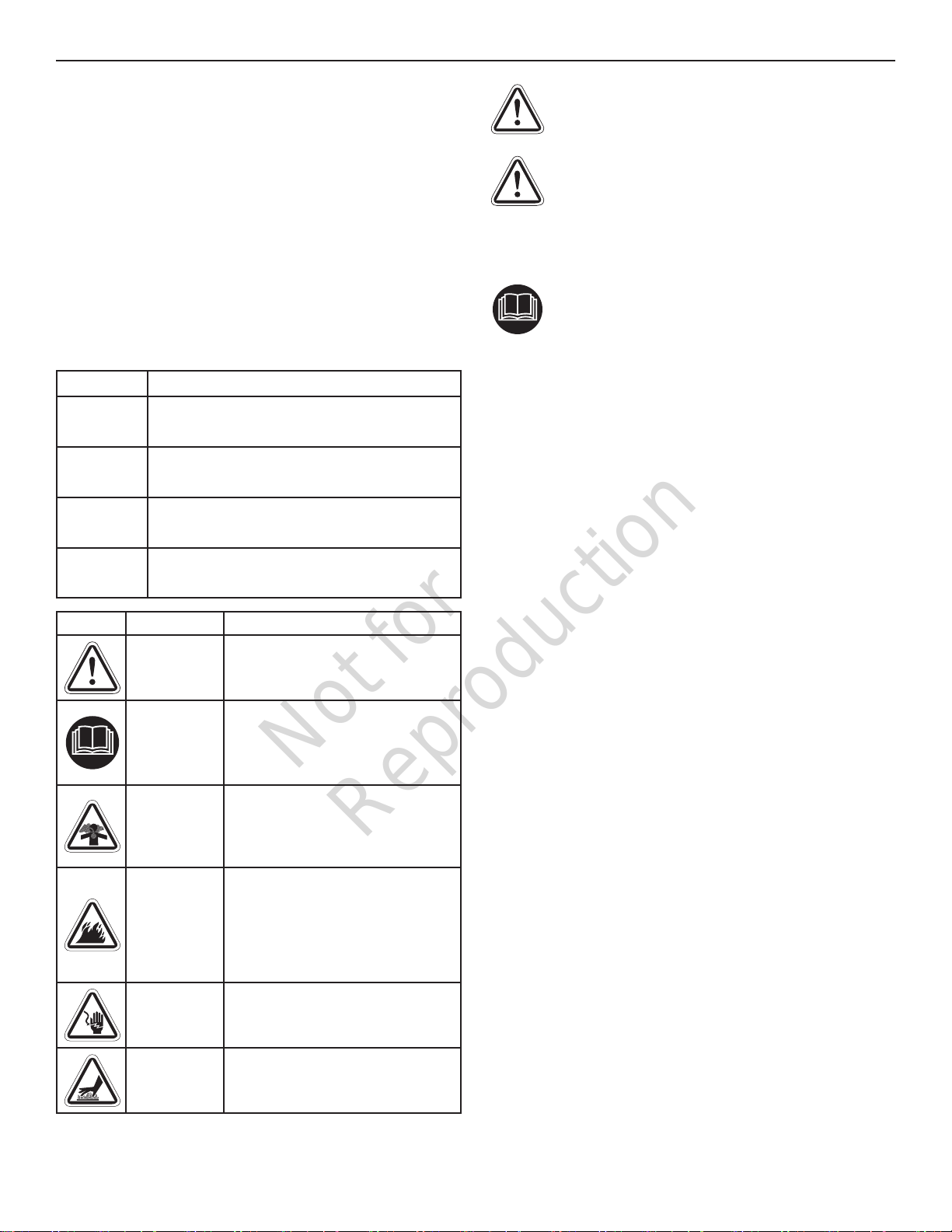
Symbols and Meanings
Signal Meaning
DANGER
WARNING
CAUTION
NOTICE
Symbol Name Explanation
Indicates a hazard which, if not avoided, will
result in death or serious injury.
Indicates a hazard which, if not avoided, could
result in death or serious injury.
Indicates a hazard which, if not avoided, could
result in minor or moderate injury.
Addresses practices not related to personal
injury.
Safety Alert
Symbol
Operator’s
Manual
Toxic Fumes
Fire
Electric
Shock
Hot Surface
Indicates a potential personal injury
hazard.
Failure to follow warnings,
instructions and operator’s manual
could result in death or serious
injury.
Engine exhaust contains carbon
monoxide, a poisonous gas that
could kill you in minutes. You
cannot smell it or see it.
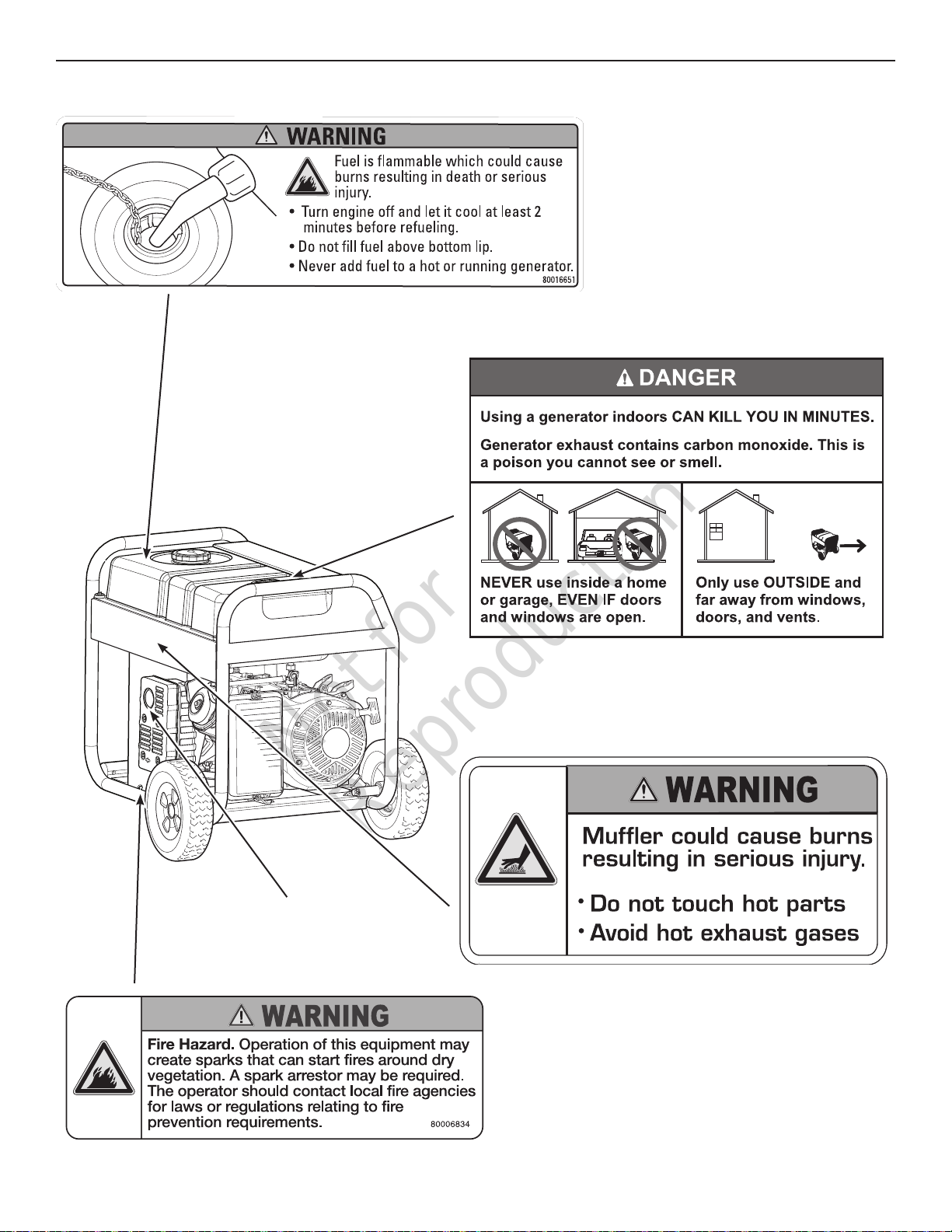
Fuel and its vapors are extremely
flammable which could cause
burns or fire resulting in death or
serious injury.
Engine exhaust could cause fire
resulting in death or serious injury.
Generator could cause electrical
shock resulting in death or serious
injury.
Muffler could cause burns or
resulting in serious injury.
WARNING! The engine exhaust from this product
contains chemicals known to the State of California to
cause cancer, birth defects, or other reproductive harm.
WARNING! Certain components in this product and
related accessories contain chemicals known to the
State of California to cause cancer, birth defects or
other reproductive harm. Wash hands after handling.
Equipment Description
Read this manual carefully and become familiar
with your outdoor generator. Know its applications,
its limitations, and any hazards involved. Save
these instructions for future reference.
The outdoor generator is an engine-driven, revolving field,
alternating current (AC) generator equipped with a voltage
regulator. The generator is designed to supply electrical power
for operating compatible electrical lighting, appliances, tools
and motor loads. The voltage regulator within the generator is
designed to automatically maintain output voltage level.
The portable generator produces power that can be used for
outdoor items using the extension cords provided or for first
time temporary home power restoration. Before your next home
power outage, install a listed transfer switch. A transfer switch is
a separate device installed by a licensed electrician that allows
the portable generator to be cord connected, using the locking
receptacle, directly into your home’s electrical system. Extension
cords connected to the portable generator’s control panel are
not intended to be a long term solution when connected to items
inside your home.
Every effort has been made to ensure that the information in this
manual is both accurate and current. However, the manufacturer
reserves the right to change, alter or otherwise improve the
generator and this documentation at any time without prior notice.
NOTICE If you have questions about intended use, contact an
authorized service dealer. This equipment is designed to be used
with Briggs & Stratton Power Products authorized parts only.
System Ground
The generator has a system ground that connects the generator
frame components to the ground terminals on the AC output
receptacles. The system ground is connected to the AC neutral
wire (the neutral is bonded to the generator frame).
Special Requirements
There may be Federal or State regulations, local codes, or
ordinances that apply to the intended use of the generator.
Please consult a qualified electrician,
the local agency having jurisdiction.
This generator is not intended to be used at a construction
site or similar activity as defined by NFPA 70-2014 (NEC)
section 590.6.
electrical inspector, or
2 BRIGGSandSTRATTON.COM
Not for
Reproduction
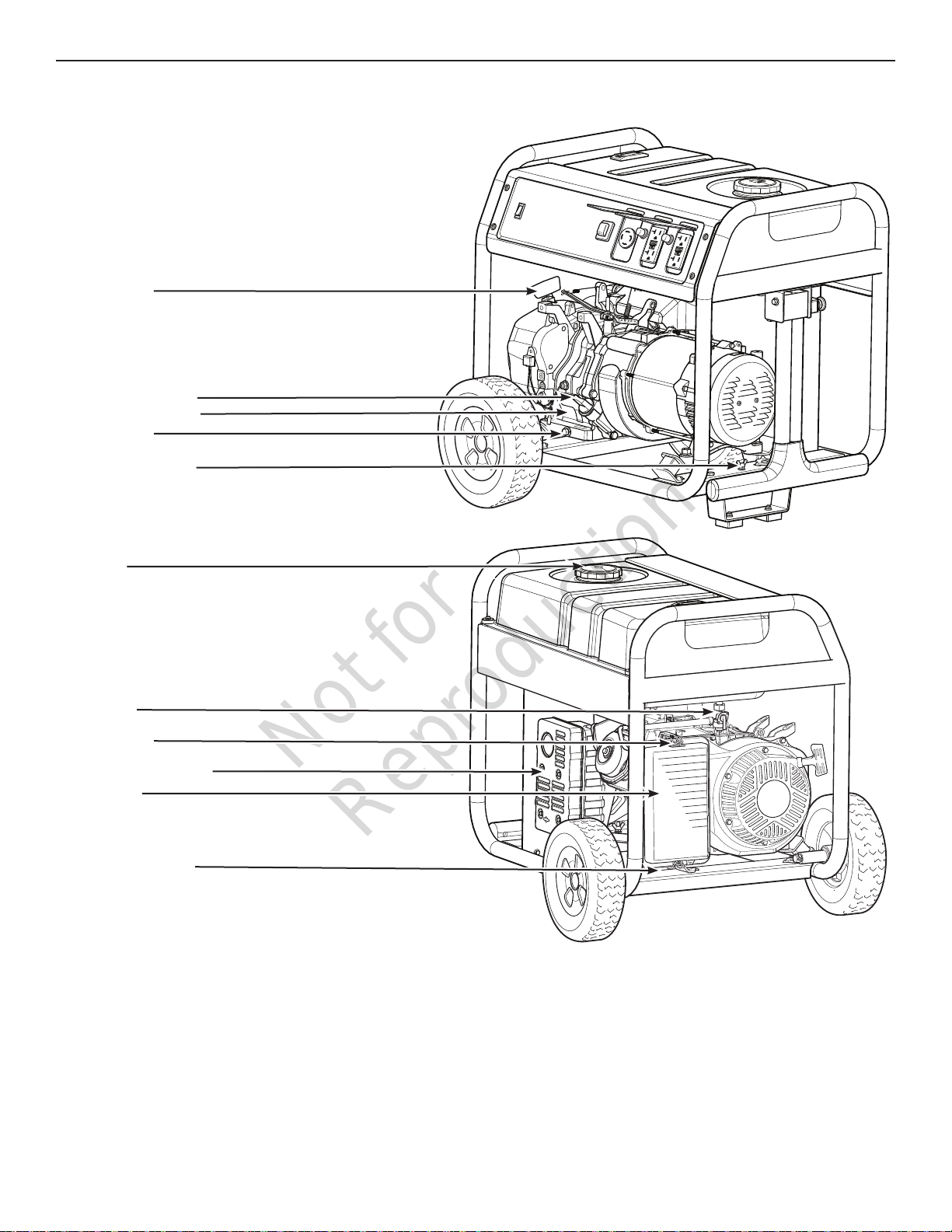
Recoil Starter
Oil Fill Cap/Dipstick
Engine Identification
Oil Drain Plug
Grounding Fastener
Equipment Description
Fuel Cap
Fuel Valve
Choke Lever
Spark Arrester Muffler
Air Cleaner
Identification Label
Air Cleaner — Filters engine intake air.
Choke Lever — Used when starting a cold engine.
Engine Identification — Provides model, type and code of engine.
Fuel Cap — Add unleaded fuel here.
Fuel Valve — Used to turn fuel supply on and off to engine.
Grounding Fastener — Consult your local agency having
jurisdiction for grounding requirements in your area.
Identification Label — Provides model and serial number of
generator.
Oil Drain Plug — Drain engine oil here.
Oil Fill Cap/Dipstick — Check and add engine oil here.
Recoil Starter — Used to start the engine manually.
Spark Arrester Muffler — Exhaust muffler lowers engine noise and
is equipped with a spark arrester screen.
3
Not for
Reproduction
Equipment Description
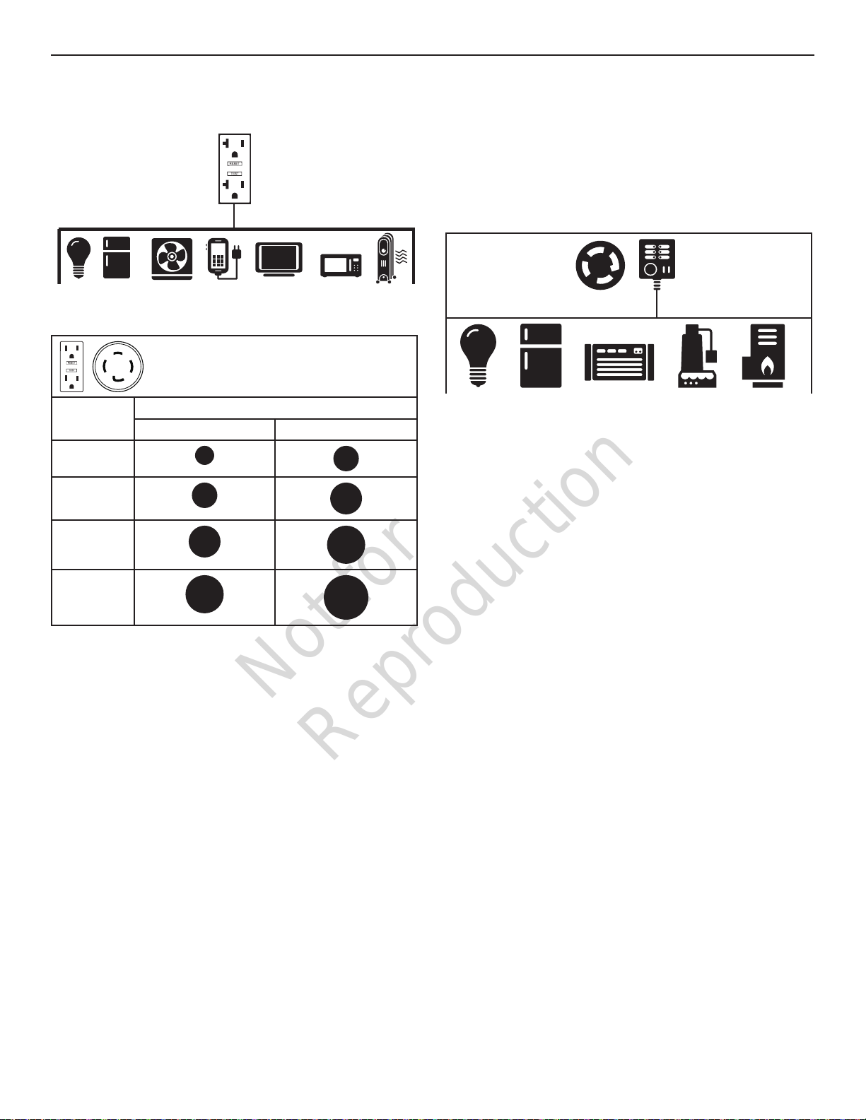
To Temporarily Restore Power
Using Extension Cords
120V
OUTLET
1. Only use cords marked for outdoor use rated for your
loads.
To Temporarily provide power
Total
Amperage
Up to 13A
Up to 15A
using extension cords
Minimum Guage, Outdoor Rated
Up to 50 FT (15 M) Up to 100 FT (30 M)
16
14
14
12
To Restore Home Power Using a Listed
Transfer Switch
Connections to your home’s electrical system must use a
listed transfer switch installed by a licensed electrician. The
connection must isolate the generator power from the utility
power and comply with all applicable laws and electrical
codes. Power your home with a 30 Amp transfer switch
system.
120/240V
Outlet
Typical Indoor Items
—
Transfer
Switch
Up to 20A
Up to 30A
2. Follow cord safety instructions.
3. Extension cords running directly into the home
increase your risk of carbon monoxide poisoning
through openings. Install carbon monoxide alarm(s).
4. Before your next home power outage, install a listed*
transfer switch.
12
10
10
8
* Certified by a Nationally Recognized Testing Laboratory
4 BRIGGSandSTRATTON.COM
that the product complies to appropriate product safety test
standards.

Not for
Reproduction
Features and Controls
Compare the illustrations with your generator to familiarize yourself with the locations of various
controls and product warnings.
Low Oil Shutdown
Engine Switch
Main Breaker
120/240 Volt AC, 30 Amp
Locking Receptacle
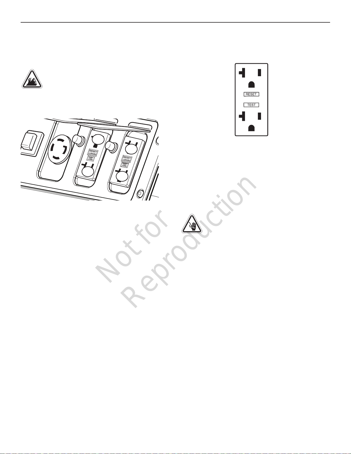
Circuit Breakers
120 Volt AC, 20 Amp
GFCI Duplex Receptacles
120 Volt AC, 20 Amp, GFCI Duplex Receptacles — Used
to supply 120 Volt AC, single phase, 60 Hz power for
electrical lighting, appliance, tool and motor loads.
120/240 Volt AC, 30 Amp Locking Receptacle — Used to
supply 120 / 240 Volt AC, single phase, 60 Hz power for
electrical lighting, appliance, tool and motor loads.
Circuit Breakers (AC) — The 120 Volt AC, 20A GFCI
duplex receptacles are provided with “push to reset” 20
Amp circuit breakers to protect the generator against
electrical overload.
Engine Switch — Set this switch to on (I) before starting
engine. Set switch to off (0) to shut off engine.
Low Oil Shutdown — This unit is equipped with a low oil
protection device. Oil must be at proper level for engine
to run. If the engine oil drops below a preset level, an oil
switch will stop the engine. Check oil level with dipstick.
Main Breaker — The receptacles are provided with a
21 Amp rocker switch main circuit breaker to protect the
generator against electrical overload.
5
Not for
Reproduction
Features and Controls
Muffler
Point away from home
202997
6 BRIGGSandSTRATTON.COM
Not for
Reproduction
Operation
Operation
Step 1: Safe Location
Before starting the portable generator there are two equally
important safety concerns regarding carbon monoxide
poisoning and fire that must be addressed.
Operation Location to Reduce the Risk of
Carbon Monoxide Poisoning
The engine exhaust of all fossil fuel burning equipment,
such as a portable generator, contains carbon monoxide,
a poisonous gas that could kill you in minutes. You cannot
smell it, see it, or taste it. Even if you do not smell exhaust
fumes, you could still be exposed to carbon monoxide gas.
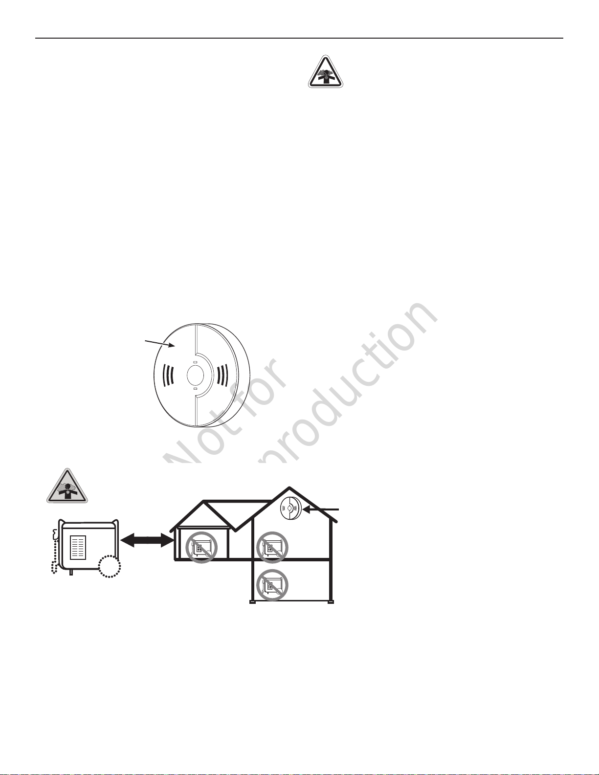
By law it is required in many states to have a carbon
monoxide alarm in operating condition in your home. A
carbon monoxide alarm is an electronic device that detects
hazardous levels of carbon monoxide. When there is
a buildup of carbon monoxide, the alarm will alert the
occupants by flashing visual indicator light and alarm.
Smoke alarms cannot detect carbon monoxide gas.
Carbon monoxide alarm
DANGER! Engine exhaust contains carbon
monoxide, a poisonous gas that could kill you in
minutes. You cannot smell it, see it, or taste it.
Even if you do not smell exhaust fumes, you could still be
exposed to carbon monoxide gas.
• Operate this product only outdoors far away from
windows, doors and vents to reduce the risk of carbon
monoxide gas from accumulating and potentially being
drawn towards occupied spaces.
• Install battery-operated carbon monoxide alarms or
plug-in carbon monoxide alarms with battery back-up
according to the manufacturer’s instructions. Smoke
alarms cannot detect carbon monoxide gas.
• Do not run this product inside homes, garages,
basements, crawlspaces, sheds, or other partiallyenclosed spaces even if using fans or opening doors
and windows for ventilation. Carbon monoxide can
quickly build up in these spaces and can linger for
hours, even after this product has shut off.
• Always place this product downwind and point the
engine exhaust away from occupied spaces.
If you start to feel sick, dizzy, or weak while using this
product, get to fresh air right away. See a doctor. You may
have carbon monoxide poisoning.
USE OUTDOORS - AVOID CARBON MONOXIDE POISONING
MUFFLER
point away
from home
CARBON MONOXIDE ALARM(S)
Install carbon monoxide alarms inside
your home. Without working carbon
monoxide alarms, you will not realize
you are getting sick and dying from
carbon monoxide poisoning.
7
Not for
Reproduction
Operation
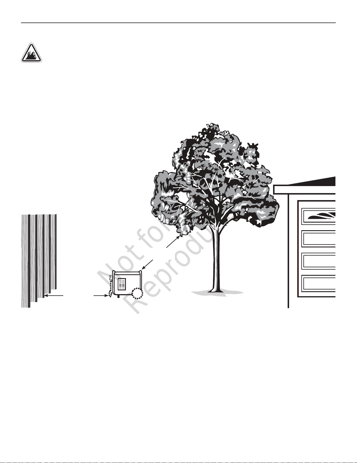
Operation Location to Reduce the Risk of Fire
WARNING!
combustibles, structures or damage fuel tank
causing a fire, resulting in death or serious injury.
• Portable generator must be at least 5 ft. (1.5 m) from
any structure, overhang, trees, windows, doors, any wall
opening, shrubs, or vegetation over 12 in. (30.5 cm) in
height.
Exhaust heat/gases could ignite
• Do not place portable generator under a deck or other
type of structure that may confine airflow. Smoke alarm(s)
must be installed and maintained indoors according to the
manufacturer’s instructions/recommendations.
• Carbon monoxide alarms cannot detect smoke.
• Do not place portable generator in manner other than
shown.
5 ft. (1.5 m)
min.
5 ft. (1.5 m)
min.
MUFFLER
8 BRIGGSandSTRATTON.COM
Not for
Reproduction
Operation
Step 2: Oil and Fuel
The generator engine is shipped from the factory filled with
10W30 oil. This allows for generator operation in a wide
range of temperature and climate conditions. For checking/
adding or changing oil see Maintenance.
Fuel must meet these requirements:
• Clean, fresh, unleaded fuel with a minimum of 87
octane.
• Gasoline with an ethanol content up to 10% is
acceptable.
E10
NOTICE Do not mix oil in fuel or modify engine to run on
alternate fuels. Use of unapproved fuels could damage
engine and will not be covered under warranty.
See High Altitude for 5,000 ft. and above.
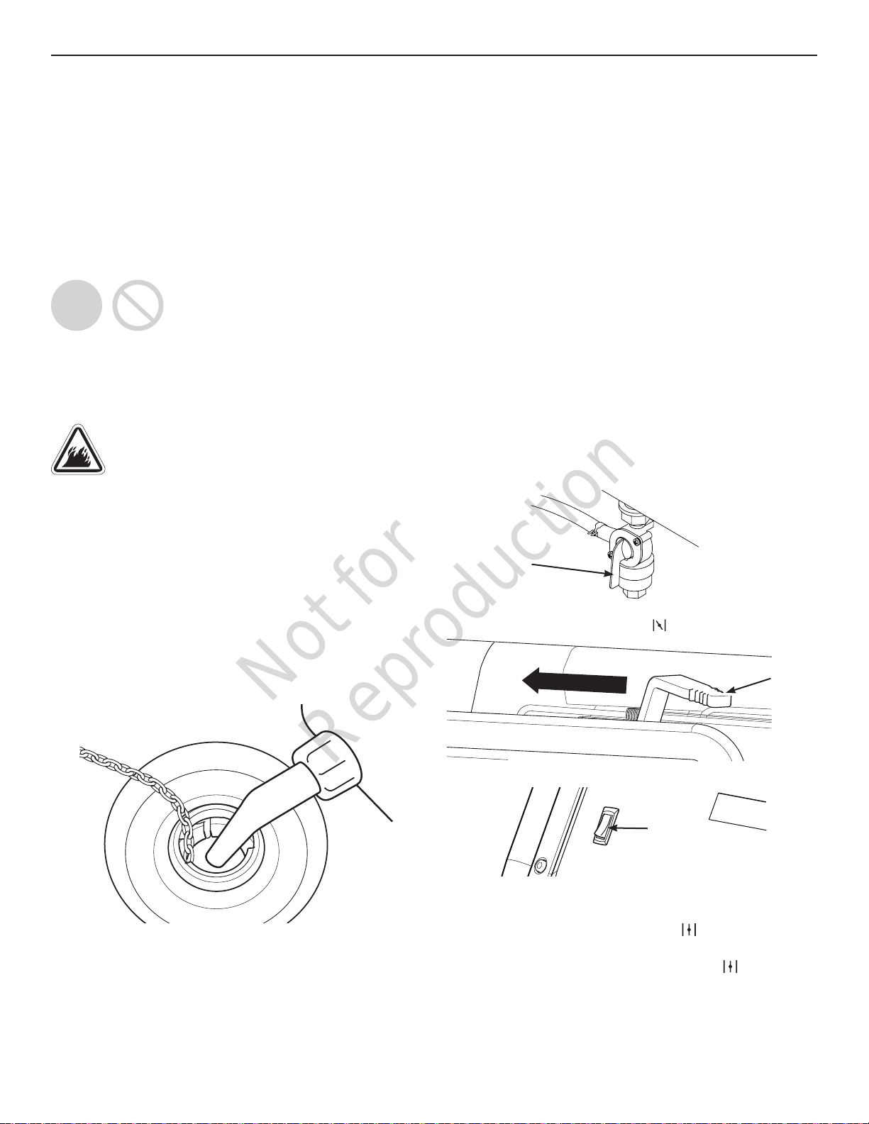
• Do not refuel during operation.
• Turn engine off and let it cool at least 2 minutes before
removing fuel cap.
• Fill fuel tank outdoors. Keep fuel away from sparks, open
flames, pilot lights, heat, and other ignition sources.
Check fuel lines, tank, cap and fittings frequently for
cracks or leaks. Replace if necessary.
1. Slowly remove fuel cap to relieve pressure in tank.
2. Slowly add unleaded fuel to fuel tank. Be careful not
E15
WARNING! Fuel and its vapors are extremely
flammable which could cause burns or fire
resulting in death or serious injury.
to fill above lip. This allows adequate space for fuel
expansion.
High Altitude
At altitudes over 5,000 ft. (1524 m), a minimum 85 octane
fuel is acceptable. To remain emissions compliant, high
altitude adjustment is required. Operation without this
adjustment will cause decreased performance, increased
fuel consumption,
See an authorized Briggs & Stratton dealer for high altitude
adjustment information. Operation of the engine at altitudes below
2,500 ft. (762 m) with the high altitude kit is not recommended.
Transporting
When transporting equipment with a vehicle or trailer, turn fuel
shutoff valve to off (0) position. Do not tip engine or equipment at
an angle which causes fuel to spill.
and increased emissions.
Step 3: Generator Start Up
Disconnect all electrical loads from the generator. Use the
following start instructions:
1. Make sure unit is outdoors on a level surface.
NOTICE Failure to operate the unit on a level surface may
cause the unit to shut down.
2. Turn the fuel valve to the on (I) position.
Fuel Valve
3. Push choke lever to choke ( ) position.
Choke Lever
3. Install fuel cap and let any spilled fuel evaporate
before starting engine.
4. Set engine switch to on (I) position.
Engine
Switch
5. Grasp recoil handle and pull slowly until slight
resistance is felt. Then pull rapidly to start engine.
6. Slowly move choke lever to run ( ) position. If engine
falters, move choke lever to half choke position until
engine runs smoothly, and then to run ( ) position.
NOTICE If engine starts but fails to run, see Low Oil
Shutdown in Features and Controls.
9
Not for
Reproduction
Operation
Step 4: Connecting Electrical Loads
Using Extension Cords
Use only grounded extension cords marked for outdoor
use rated for your loads. Follow cord safety instructions.
WARNING! Damaged or overloaded extension
cords could overheat, arc, and burn resulting in
death or serious injury.
NOTICE For best results when plugging into the 120 Volt
receptacles, plug items to be powered in sequence as
shown.
1
2
3
4
NOTICE For generator output required see Generator
Capacity. Connect electrical loads in off position then turn
on for operation.
120 Volt AC, 20 Amp, GFCI Duplex Receptacles
Use each receptacle to operate 120 Volt AC, single-phase,
60 Hz electrical loads requiring up to 2,400 Watts (2.4 kW)
at 20 Amps of current.
Ground Fault Protection
The duplex receptacles are equipped with Ground Fault
Circuit Interrupter (GFCI) protection. The GFCI protects
against electrical shock that may be caused if your body
becomes a path which electricity travels to reach ground.
When protected by a GFCI, one may still feel a shock, but
the GFCI is intended to cut current off quickly enough so
that a person in normal health should not suffer any serious
electrical injury.
WARNING! Generator voltage could cause
electrical shock or burn resulting in death or
serious injury. Contact with the hot and neutral
conductor at the same time could cause electrical shock
or burn, even if the circuit is GFCI protected.
Testing the GFCI
Test your GFCI outlet prior to each use, as follows:
• Push the “Test” button. The “Reset” button should pop
out, which should allow no power to reach the outlet.
• Press the “Reset” button firmly until it is fully in place
and locks in that position. If the GFCI outlet does not
reset properly, do not use the outlet. Call or take your
generator to a local service center.
• If the GFCI trips by itself at any time, reset and test the
outlet.
10 BRIGGSandSTRATTON.COM
Not for
Reproduction
Operation
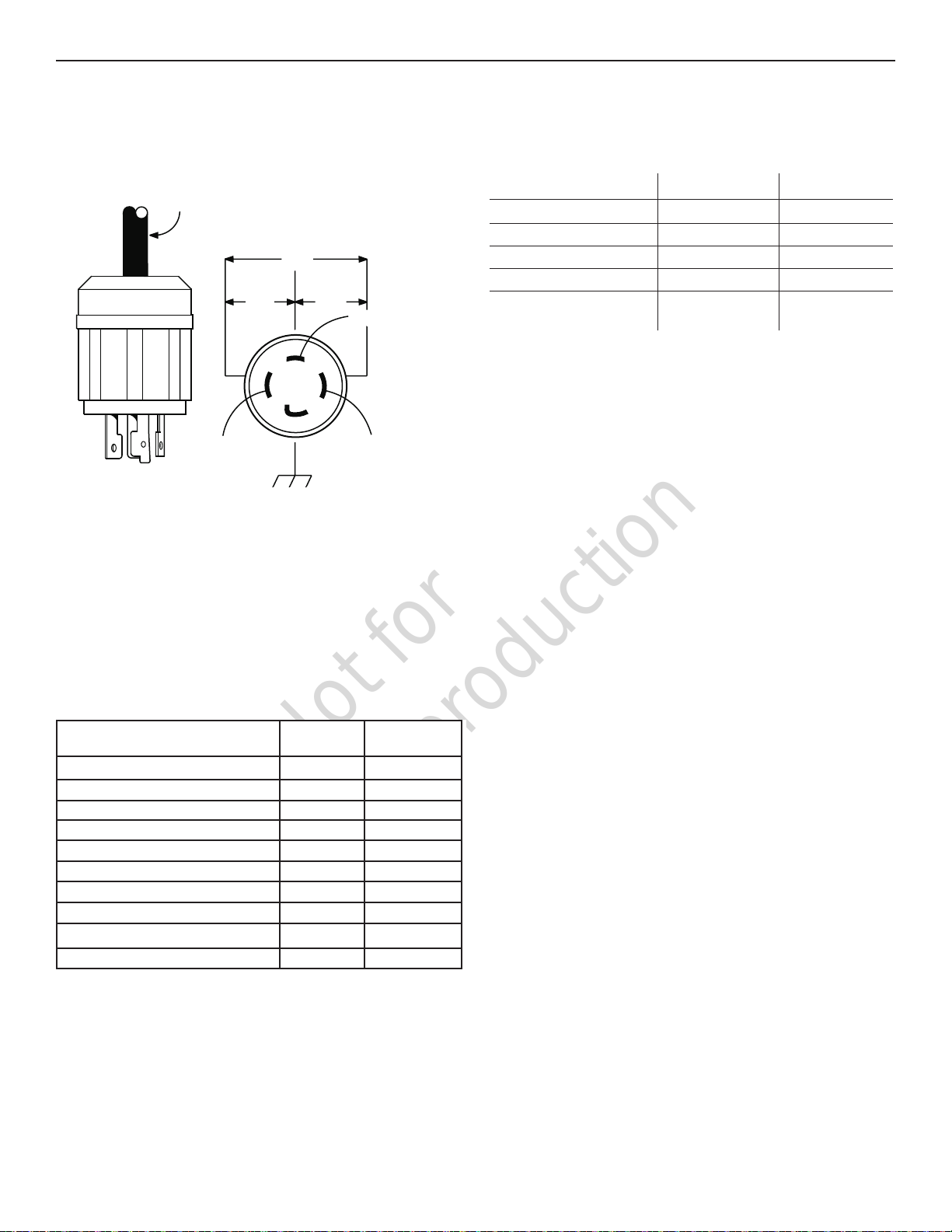
120/240 Volt AC, 30 Amp, Locking Receptacle
Use a NEMA L14-30 plug with this receptacle. Connect a
4-wire cord set rated for 250 Volt AC loads at 30 Amps.
The generator’s locking receptacle is not protected by a
GFCI.
4-Wire Cord Set
240V
120V
Y (Hot)
NEMA L14-30
This receptacle powers 120/240 Volt AC, 60 Hz, single
phase loads requiring up to 5,000 Watts of power (5.0 kW)
at 20.8 Amps for 240 Volts or two independent 120 Volt
loads at 20.8 Amps each.
120V
W (Neutral)
X (Hot)
Ground (Green)
Generator Capacity
To make sure your generator can supply enough running
watts and starting watts for the items you will power at the
same time, follow these simple steps:
1. Select the items you will power at the same time. See
following list for typical wattages.
Tool or Appliance
Light Bulb - 75 Watt 75 Sump Pump 800 1200
Refrigerator/Freezer 800 2000
Water Well Pump - 1/3 HP 1000 2000
Window AC - 10,000 BTU 1200 1800
Furnace Fan Blower - 1/2 HP 800 1300
Microwave Oven - 1000 Watt 1000 Color Television - 42” 280 -
Personal Computer w/17” monitor 800 Garage Door Opener - 1/2 HP 480 520
* Typical wattages listed are approximate only. Check tool
or appliance for actual wattage.
Running
Watts*
Starting
Watts
2. Total the running watts. This is the amount of power
your generator must produce to keep your items
running. See following example:
Example
Tool or Appliance Running Watts Starting Watts
Window air conditioner
Refrigerator 800 2000
Television 280 —
Light (75 Watts) 75 —
Total running watts = 2355
Highest starting watts = 2000
Total generator watts required = 4355
3. Estimate the starting watts you will need. Because not
all motors start at the same time, total starting wattage
can be estimated by adding only the item with the
highest additional starting watts requirements to the
total running watts from step 2.
Power Management
To manage generator power, sequentially add loads as
follows:
1. With nothing connected to generator, start the engine
outdoors.
2. Plug in and turn on the first load, preferably the largest
load you have.
3. Permit the generator output to stabilize (engine runs
smoothly and attached device operates properly).
4. Plug in and turn on the next load.
5. Again, permit the generator to stabilize.
6. Repeat steps 4 and 5 for each additional load.
Never add more loads than the generator capacity. Take
special care to consider surge loads in generator capacity.
1200 1800
2355 Total
Running Watts
2000 Highest
Starting Watts
Step 5: Generator Shutdown
1. Turn off and unplug all electrical loads from generator
panel receptacles. Never stop engine with electrical
devices plugged in and turned on.
2. Let engine run at no-load for one minute to stabilize
internal temperatures of engine and generator.
3. Push engine switch to off (0) position.
4. Move fuel valve to off (0) position.
11
 Loading...