

Briggs & Stratton 030319, 030320 Owner’s Manual
BRiGGS & STRATTON
I_!_J_WARNING
Before using this product, read this manual and follow all
Safety Rules and Operating Instructions.
BP,IGGS & STRATTON POWER PRODUCTS GROUP, LLC
JEFFERSON,WiSCONSiN, U.S.A.
ADVERTENCIA
Antes de utilizar el producto, lea este manual y siga todas [as
Reglas de Segur[dad e Instrucc[ones de Uso.
Manual No, [99399GS
Revision - (04/05/2006)
SAVE THESE INSTRUCTIONS
TABLE OF CONTENTS
Safety Rules .................................... 2-4
Features and Controls ............................. 5
Assembly ...................................... 6-7
Operation .................................... 8-II
Specifications ................................... 12
Maintenance ................................. 13-16
Storage ........................................ 17
Troubleshooting ................................. [8
Notes .................................... 19 & 22
Emissions Control _¢arranties ................... 20-2 [
_¢arranty ...................................... 23
Espa_o[ ..................................... 24-44
EQUIPMENT
DESCRmPTiON
Read this manual carefully and become
v- familiar with your generator. Know its
applications, its limitations and any hazards
invomved.
The generators are an engine-driven, revolving field,
alternating current (AC) generator. It was designed to
supply electrical power for operating compatible electrical
lighting, appliances, tools and motor loads.The generator's
revolving field is driven at about 3,600 rpm by a single°
cylinder engine.
SAFETY RULES
This isthe safety alertsymbol. Itisused to
alertyou to potential personal iniury hazards.
Obey all safety messages that follow this
symbol to avoid possible iniury or death.
The safety alert symbol (_) is used with a signal word
(DANGER, CAUTION,WARNING), a pictorial and/or a
safety message to alert you to hazards. DANGER indicates
a hazard which, if not avoided, will result in death or serious
iniury. WARNING indicates a hazard which, if not avoided,
could result in death or serious iniury. CAUTION
indicates a hazard which, if not avoided, might result in
minor or moderate iniury. CAUTION, when used
without the alert symbol, indicates a situation that could
result in equipment damage. Follow safety messages to
avoid or reduce the risk of iniury or death.
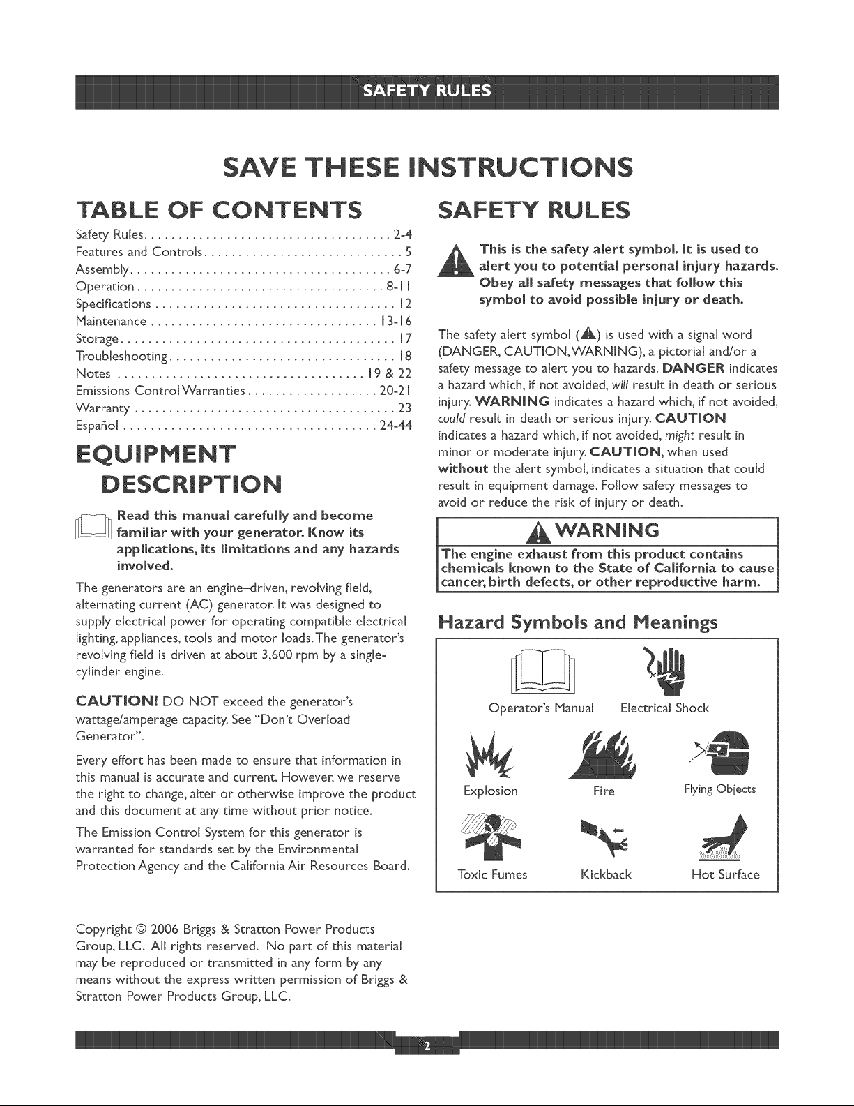
Hazard Symbols and Meanings
CAUTION! DO NOT exceed the generator's
wattage/amperage capacity. See '°Don't Overload
Generator".
Every effort has been made to ensure that information in
this manual is accurate and current. However, we reserve
the right to change, alter or otherwise improve the product
and this document at any time without prior notice.
The Emission Control System for this generator is
warranted for standards set by the Environmental
Protection Agency and the California Air Resources Board.
Copyright © 2006 Brigs & Stratton Power Products
Group, LLC. All rights reserved. No part of this material
may be reproduced or transmitted in any form by any
means without the express written permission of Briggs &
Stratton Power Products Group, LLC.
Operator's Nanual Electrical Shock
Explosion Fire FlyingObjects
Toxic Fumes Kickback Hot Surface
WARNING
WARNING
Operate generator ONLY outdoors.
Keep exhaust gas from entering a confined area through
windows, doors, ventilation intakes or other openings.
. DO NOT operate generator inside any building or enclosure
(even if doors or windows are open), including the generator
compartment of a recreational vehicle (RV).
WARNmNG
, When using generator for backup powea notify utihty
company. Use approved transfer equipment to isolate
generator from electric utility.
Use a ground fault circuit interrupter (GFC[) in any damp or
highly conductive area, such as metal decking or steel work.
DO NOT touch bare wires or receptacles.
DO NOT use generator with electrical cords which are worn,
frayed, bare or otherwise damaged.
DO NOT operate generator in the rain or wet weathe[:
DO NOT handle generator or electrical cords while standing
in watelq while barefoot, or while hands or feet are wet.
DO NOT allow unqualified persons or children to operate or
service generatol:
WARNING
WHEN ADDING OR DRAINING FUEL
Turn generator OFF and let it coo[ at [east 2 minutes before
removing fuel cap. Loosen cap slowly to relieve pressure in
tan[<.
Fill or drain fuel tan[< outdoors.
DO NOT overfill tank°Allow space for fuel expansion.
_%/ait for spilled fuel to evaporate before starting engine.
Keep fuel away from sparks, open flames, pilot lights, heat, and
other ignition sources.
DO NOT light a cigarette or smoke.
NHEN STARTING EQUIPNENT
Ensure spark plug, muff[era:fuel cap and air cleaner are in place.
DO NOT crank engine with spar[< plug removed.
WHEN OPERATING EQUIPNENT
DO NOT tip engine or equipment at angle which causes fuel
to spill
This generator is not for use in mobile equipment or marine
applications,
NHEN TRANSPORTING OR REPAIRING
EQUIPNENT
IN TANK
Store away from furnaces, stoves, water heaters, clothes
dryers or other appliances that have pilot light or other
ignition source because they can ignite fuel vapors.
When starting engine, pull cord slowly until resistance is felt
and then pull rapidly to avoid kickback°
NEVER start or stop engine with electrical devices plugged in
and turned on.
WARNING
This generator does not meet U. S.Coast Guard Regulation
33CFR-[83 and should not be used on marine applications.
Failure to use the appropriate U. S.Coast Guard approved
generator could result in death or serious injury and/or
property damage.
WARNING
WHEN ADJUSTING OR MAKING REPAIRSTO¥OUR
GENERATOR
Disconnect the spar[< plug wire from the spar[< plug and place
the wire where it cannot contact spark plug.
WNENTESTING FOR ENGINE SPARK
* Use approved spar[< plug testen
DO NOT check for spark with spark plug removed.
CAUTION
DO NOT tamper with governed speed. Generator supplies
correct rated frequency and voltage when running at governed
spee&
DO NOT modify generator in am/way.
WARNING
DO NOT touch hot surfaces and avoid hot exhaust gases.
Allow equipment to cool before touching.
Keep at [east 5 ft. ([ 52 cm) clearance on at[ sides of generator
including overhea&
Code of Federal Regulation (CFR) Title 36 Parks, Forests, and
Public Property require equipment powered by an internal
combustion engine to have a spar[< arrester, maintained in
effective working ordemqcomplying to USDA Forest service
standard 5100-1C or later revision. In the State of California a
spar[< arrester is required under section 4442 of the California
Public resources code. Other states may have similar laws.
See "Don't Overload Generator".
Start generator and let engine stabilize before connecting
electrical loads.
Connect electrical loads in OFF position, then turn ON for
operation.
Turn electrical loads OFF and disconnect from generator
before stopping generaton
Use generator only for intended uses.
[f you have questions about intended use, as[< dealer or ca[[
[-800-743-4115.
Operate generator only on [eve[ surfaces.
DO NOT expose generator to excessive moisture, dust, dirt,
or corrosive vapors.
DO NOT insert any objects through cooling slots.
If connected devices overheat, turn them off and disconnect
them from generatom:
Shut off generator if:
-e[ectrica[ output is lost;
-equipment sparks, smokes, or emits flames;
-unit vibrates excessive[y_
1
KNOWYOUR GENERATOR
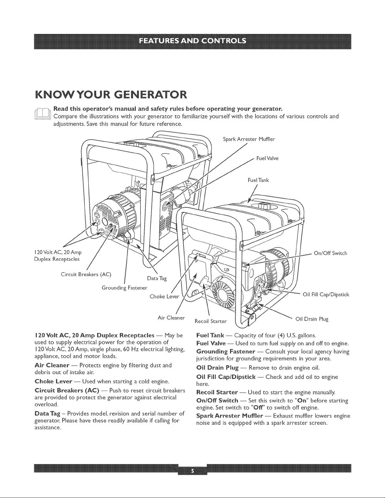
Read this operator's manua[ and safety fumes before operating your generator.
Compare the illustrations with your generator to famiIhrize yourself with the locations of various controls and
adjustments. Save this manual for future reference°
SparkArrester Muffler
Fue[Valve
Fuel Tank
120 Volt AC, 20 Amp
Duplex Receptacles
Circuit Breakers (AC)
Data Tag
Grounding Fastener
Choke Lever
Air Cleaner
[ 20 Volt AC, 20 Amp Duplex Receptacles -- May be
used to supply electrical power for the operation of
[ 20Volt AC, 20 Amp, single phase, 60 Hz electrical lighting,
app[hnce, too[ and motor loads.
Air Cleaner -- Protects engine by fi[terhg dust and
debris out of intake air.
Choke Lever -- Used when starting a cold engine.
Circuit Breakers (AC) -- Push to reset circuit breakers
are provided to protect the generator against electrical
overload.
DataTag - Provides model, revision and serial number of
generator. Please have these readily available if calling for
assistance.
On/Off Switch
Oil Fill Cap/Dipstick
Recoil Starter
Oil Drain Plug
Fuel Tank -- Capacity of four (4) U.& gallons.
Fuel Valve -- Used to turn fuel supply on and off to engine.
Grounding Fastener -- Consult your local agency having
jurisdiction for grounding requirements in your area,
Oim Drain Pmug -- Remove to drain engine oil.
Oil Fill Cap/Dipstick -- Check and add oil to engine
here.
Recoil Starter -- Used to start the engine manually.
On/Off Switch -- Set this switch to "On" before starting
engine. Set switch to "Off' to switch off engine.
Spark Attester Muffler- Exhaust muffler lowers engine
noise and is equipped with a spark arrester screen.
ASSENBL¥
Your generator requires some assembly and is ready for
use after it has been properly serviced with the
recommended oil and fuel.
If you have any problems with the assembly of your
generator, please call the generator heIpJine at
[°800°743°4 [ [ 5. If calling for assistance, please have the
model, revision, and serial number from the data tag available.
See "KnowYour Generator" for data tag location.
Unpacking the Generator
1. Set the carton on a rigid flat surface.
2. Open carton completely by cutting each corner from
top to bottom.
3. Cut ties holding accessory kit and axle to generator
and remove everything from carton.
4. Leave generator on carton to install wheel kit.
[nstallWheel Kit
NOTE: Wheel kit is not intended for over-the-road use.
You will need the following tools to install these
components:
I3ram wrench
Socket wrench with a I 3mm socket
o 9/16" wrench
o Pliers
o Safety glasses
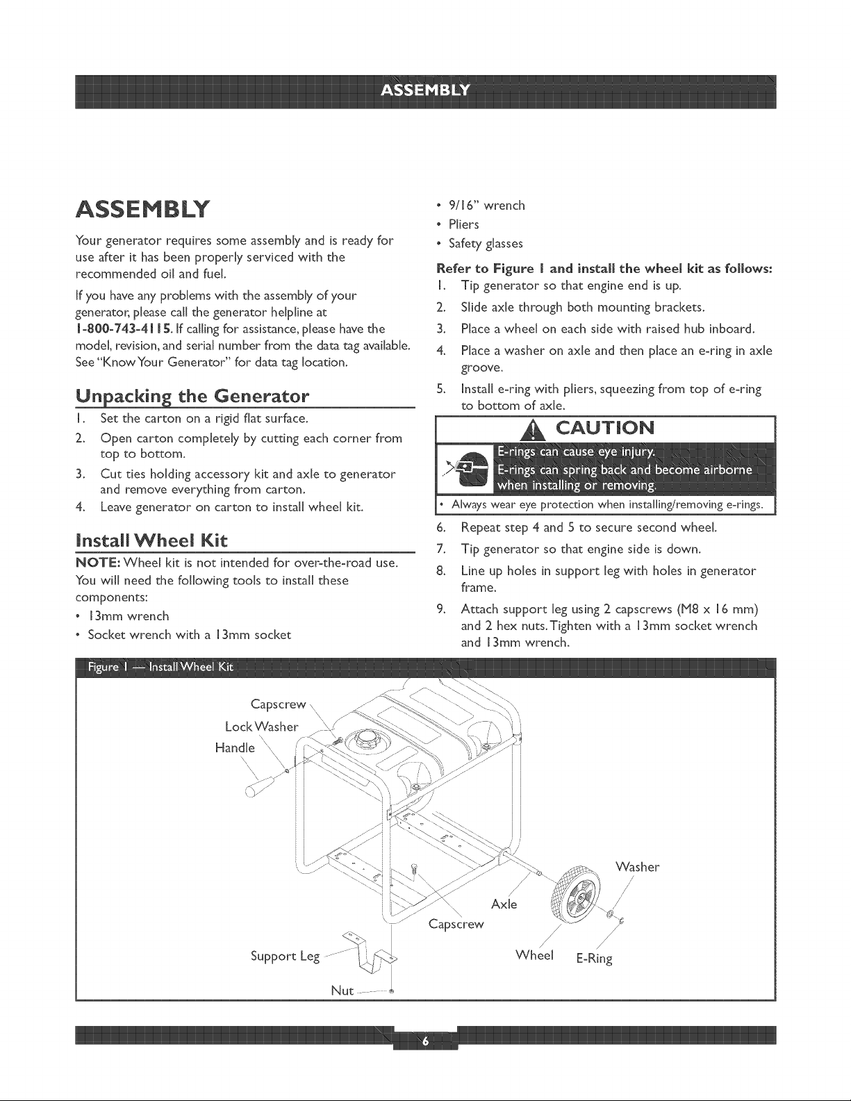
Refer to Figure ( and install the wheel kit as follows:
I. Tip generator so that engine end is up.
2. Slide axle through both mounting brackets.
3. Place a wheel on each side with raised hub inboard.
4. Place a washer on axle and then place an e-ring in axle
groove.
5. Install e-ring with pliers, squeezing from top of e-ring
to bottom of axle.
CAUTmON
Always wear eye protection when installing/removing e-rings,
6. Repeat step 4 and 5 to secure second wheel.
7. Tip generator so that engine side is down.
8. Line up holes in support leg with holes in generator
frame.
.
Attach support leg using 2 capscrews (b18 x 16 mm)
and 2 hex nuts.Tighten with a 13ram socket wrench
and 13mm wrench.
Capscrew \\
Lock 'v_/asher
Handle _\,
\
\\
_asher
/
/
Capscrew
/ /
Axle /
/
/ /
/ j/
Wheel E-Ring
I0. Returngeneratortonormaloperatingposition(resting
onwheelsandsupportleg).
I I. Attach handle using a long (M8 x 45mm) cap screw
and lock washer.Tighten with a 9/16" wrench.
BEFORE STARTING THE
ENGINE
Add Engine Oil
CAUTION! Any attempt to crank or start the engine
before it has been properly serviced with the
recommended oil may result in an engine failure.
I. Place generator on a flat, level surface.
2. Clean area around oil fill and remove yellow oil fill cap.
NOTE: See the section °°Oil" on page 14 to review oil
recommendations.Verify provided oil bottle is correct
viscosity for current ambient temperature.
3. Using oil funnel (optional), slowly pour contents of
provided oil bottle into oil fill opening.
4. Replace oil fill cap and fully tighten.
Add Fuel
All fuel is not the same. If a starting or performance
problem is encountered immediately after new fuel has
been used, try another service station or change brands.
NOTE: This engine is certified to operate on gasoline.
Exhaust Emissions Control System: EM (Engine Modifications).
WANNING
WNEN ADDING FUEL
Turn generator OFF and let it coo[ at least 2 minutes before
removing fuel cap. Loosen cap slowly to relieve pressure in tan[<.
Fill fuel tank outdoors.
DO NOT overfill tank.Allow space for fuel expansion_
Wait for spilled fuel to evaporate before starting engine.
Keep fuel away from sparks, open flames, pilot lights, heat, and
other ignition sources.
DO NOT light a cigarette or smoke_
Type of Fuel
I. Always use clean, fresh, UNLEADED gasoline with a
minimum of 87 octane/87 AKI (91 RON). DO NOT
mix oil with fuel. DO NOT modify the engine fuel
system or carburetor to run on alternative fuels.
NOTE: Fuel with up to 10% ethanol (gasohol) or up to
15% MTBE (methyl tertiary butyl ether), is acceptable.
IMPORTANT: Use of any fuel other than those approved
above will void warranty. Some areas require that fuel
pumps be marked if the fuel contains alcohols or ethers. If
you are not sure if your fuel contains alcohol or ethers that
are different than those approved above, then check with
the service station operator.
2. Clean area around fuel fill cap, remove cap.
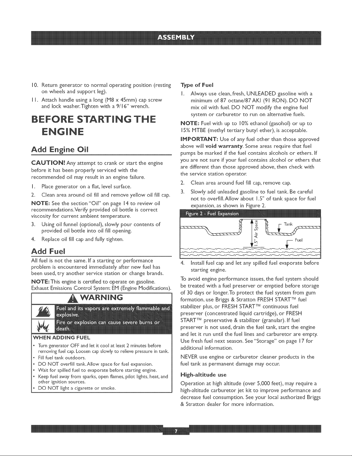
3. Slowly add unleaded gasoline to fuel tank. Be careful
not to overfill.Allow about 1.5" of tank space for fuel
expansion, as shown in Figure 2.
_,_ _ Fuel
4. Install fuel cap and let any spilled fuel evaporate before
starting engine.
To avoid engine performance issues, the fuel system should
be treated with a fuel preserver or emptied before storage
of 30 days or longer.To protect the fuel system from gum
formation, use Briggs & Stratton FRESH START TMfuel
stabilizer plus, or FRESH START TMcontinuous fuel
preserver (concentrated liquid cartridge), or FRESH
START TMpreservative & stabilizer (granular). Iffuel
preserver is not used, drain the fuel tank, start the engine
and let it run until the fuel lines and carburetor are empty.
Use fresh fuel next season. See "Storage" on page 17 for
additional information.
NEVER use engine or carburetor cleaner products in the
fuel tank as permanent damage may occur.
Nigh-altitude use
Operation at high altitude (over 5,000 feet), may require a
high-altitude carburetor iet kit to improve performance and
decrease fuel consumption. See your local authorized Briggs
& Stratton dealer for more information.
1
USING THE GENERATOR
System 6; round
The generator has a system ground that connects the
generator frame components to the ground terminals on
the AC output receptacles.The system ground is connected
to the AC neutral wire (see '°Equipment Description",
earlier in this manual).
Speciam Requirements
There may be Federal or State Occupational Safety and
Health Administration (OSHA) regulations, local codes, or
ordinances that apply to the intended use of the generator.
Please consult a qualified electridan, electrical inspector, or
the local agency having jurisdiction.
o In some areas, generators are required to be registered
with local utility companies.
o If the generator Jsused at a construction site, there may
be additional regulations which must be observed.
Connecting to a Buimding's Electrical
System
Connections for standby power to a building's electrical
system must be made by a qualified electrician.The
connection must isolate the generator power from utility
power, and must comply with all applicable laws and
electrical codes.
Generator Location
Generator Clearance
WANNmNG
Keep at least 5 ft. (152 cm) clearance on all sidesof generator
including overhead°
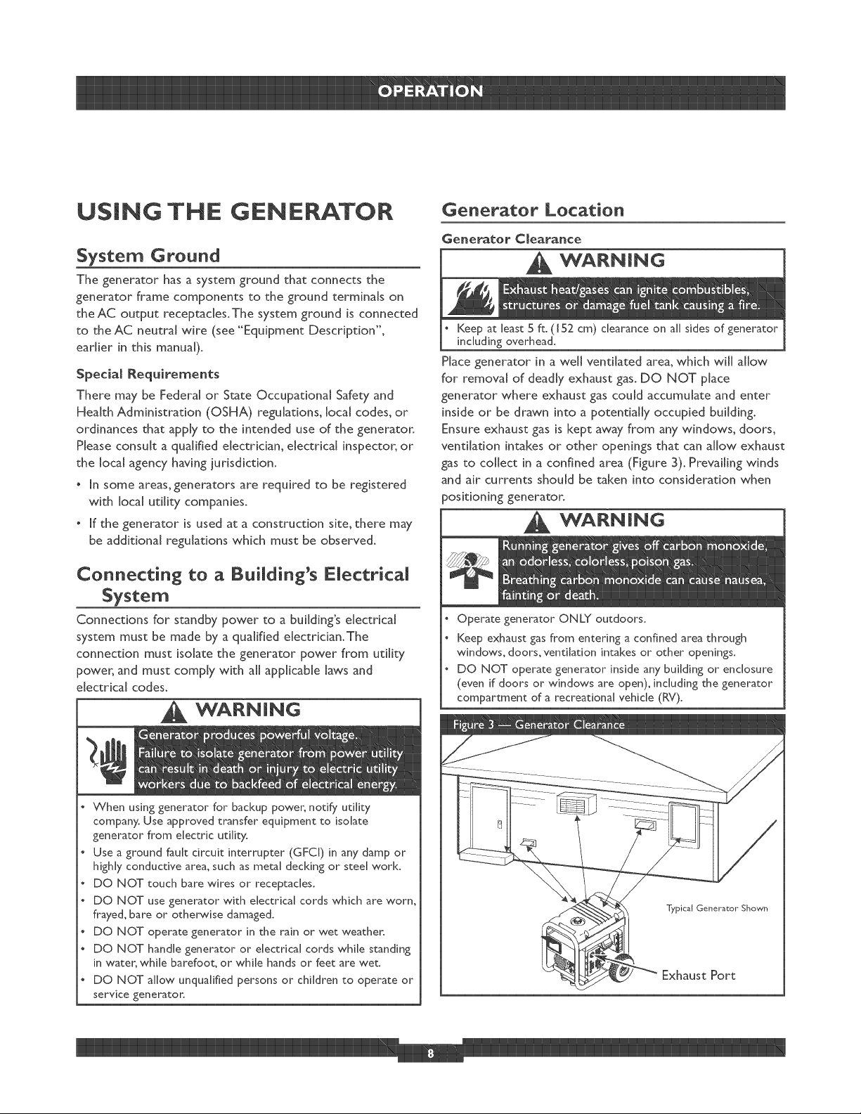
Place generator in a well ventilated area, which will allow
for removal of deadly exhaust gas. DO NOT place
generator where exhaust gas could accumulate and enter
inside or be drawn into a potentially occupied building.
Ensure exhaust gas is kept away from any windows, doors,
ventilation intakes or other openings that can allow exhaust
gas to collect Jna confined area (Figure 3). Prevailing winds
and air currents should be taken into consideration when
positioning generator.
WANNmNG
Operate generator ONLY outdoors.
Keep exhaust gasfrom entering aconfined area through
windows, doors, ventilation intakes or other openings.
DO NOT operate generator inside any building or enclosure
(even if doors or windows are open), including the generator
compartment of a recreational vehicle (RV).
service generatol:
Typical Generator Shown
Exhaust Port
OPERATING THE
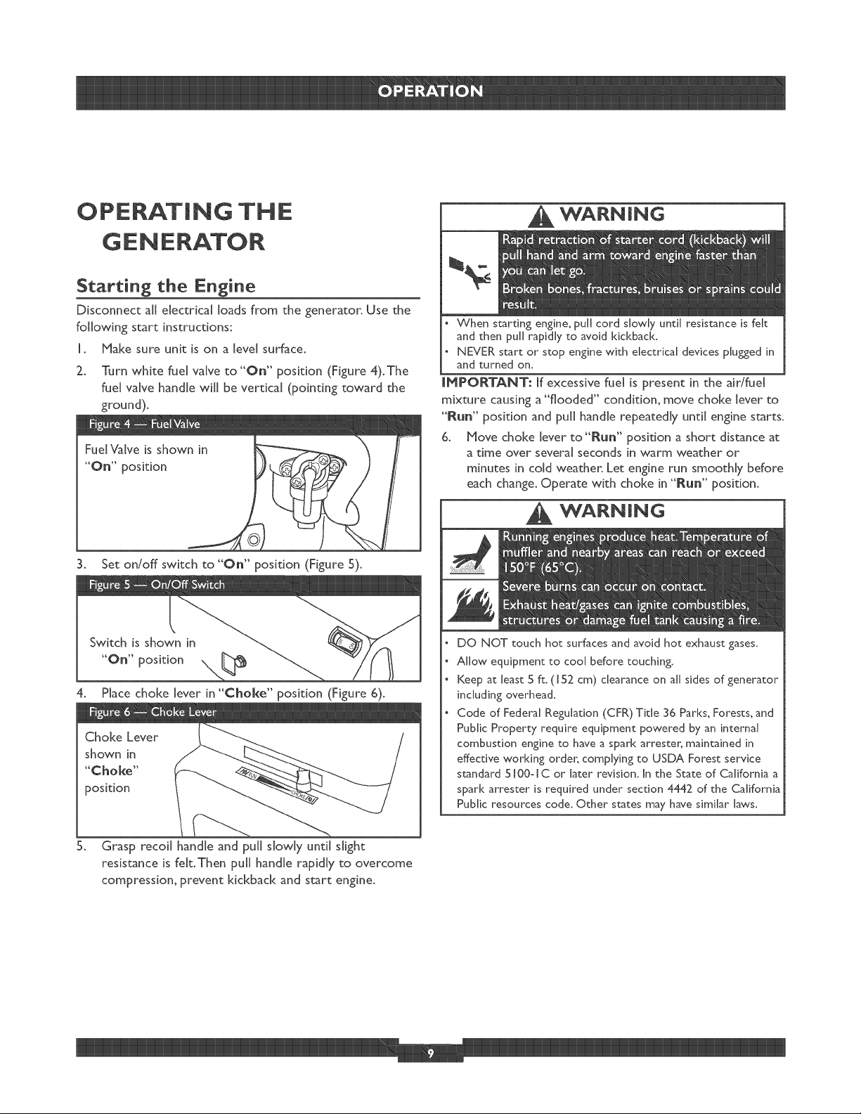
Starting the Engine
Disconnect all electrical loads from the generator. Use the
following start instructions:
I. Make sure unit is on a level surface.
2. Turn white fuel valve to"On" position (Figure 4).The
fuel valve handle will be vertical (pointing toward the
ground).
3. Set on!off switch to"On" position (Figure 5).
WARNmNG
When starting engine, pull cord slowly until resistance is felt
and then pull rapidly to avoid kid<bad<.
NEVERstart or stop engine with electrical devices plugged in
and turned on,
IMPORTANT: if excessive fuel is present in the air/fuel
mixture causing a "flooded" condition, move choke [ever to
"Run" position and pull handle repeatedly until engine starts.
B. Move choke lever to"P_un" position a short distance at
a time over several seconds in warm weather or
minutes in cold weather. Let engine run smoothly before
each change. Operate with choke in "[_un" position.
WARNING
5. Grasp recoil handle and pull slowly until slight
resistance is felt.Then pull handle rapidly to overcome
compression, prevent kickback and start engine.
DO NOT touch hot surfaces and avoid hot exhaust gases.
Allow equipment to cool before touching.
Keep at least 5 ft. (152 cm) clearance on all sides of generator
including overhead.
Code of Federal Regulation (CFR) Title 36 Parks, Forests, and
Public Property require equipment powered by an internal
combustion engine to have a spar[< attester, maintained in
effective working order, complying to USDA Forest service
standard 5[00-IC or later revision. In the State of California a
spar[< attester is required under section 4442 of the California
Public resources code. Other states may have similar laws.
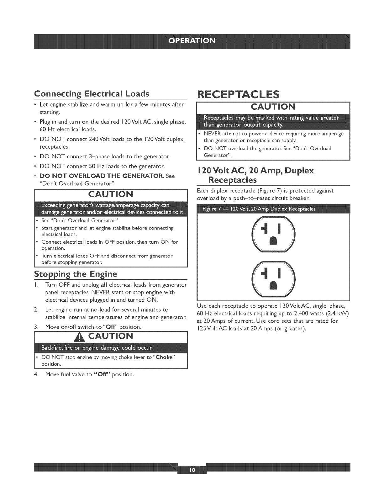
Connecting Electrical Loads
Let engine stabilize and warm up for a few minutes after
starting.
o Plug in and turn on the desired J2OVokAC, single phase,
60 Hz electrical loads.
o DO NOT connect 240Voff loads to the J20Vok duplex
receptacles.
o DO NOT connect 3-phase loads to the generator.
o DO NOT connect 50 Hz loads to the generator.
o DO NOT OVERLOAD THE GENERATOR° See
"Don't Overload Generator".
See"Don't Overload Generator"°
Start generator and let engine stabilize before connecting
electrical loads.
Connect electrical loads in OFF position, then turn ON for
operation.
Turn electrical loads OFF and disconnect from generator
before stopping generator.
Stopping the Engine
I. Turn OFF and unplug all electrical loads from generator
panel receptacles. NEVER start or stop enghe with
electrical devices plugged in and turned ON.
2. Let engine run at no°load for several minutes to
stabilize internal temperatures of engine and generator.
3. Move on/off switch to "Off" position.
CAUTION
than generator or receptacle can supply.
DO NOT overload the generator, See "Don't Overload
NEVER attempt to power a device requiring more amperage
Generator",
[ 20 Volt AC, 20 Amp, Duple×
Receptacles
Each duplex receptacle (Figure 7) is protected against
overload by a push-to-reset circuit breaker.
Use each receptacle to operate 120Volt AC, single-phase,
60 Hz electrical loads requiring up to 2,400 watts (2.4 k_¢)
at 20Amps of current. Use cord sets that are rated for
125 Volt AC loads at 20 Amps (or greater).
DO NOT stop engine by moving choke [ever to "Choke"
position.
4. Move fuel valve to "Off" position.
DON'T OVERLOAD
C adty
You must make sure your generator can supply enough
rated (running) and surge (starting) watts for the items you
will power at the same time. Follow these simple steps:
I. Select the items you will power at the same time.
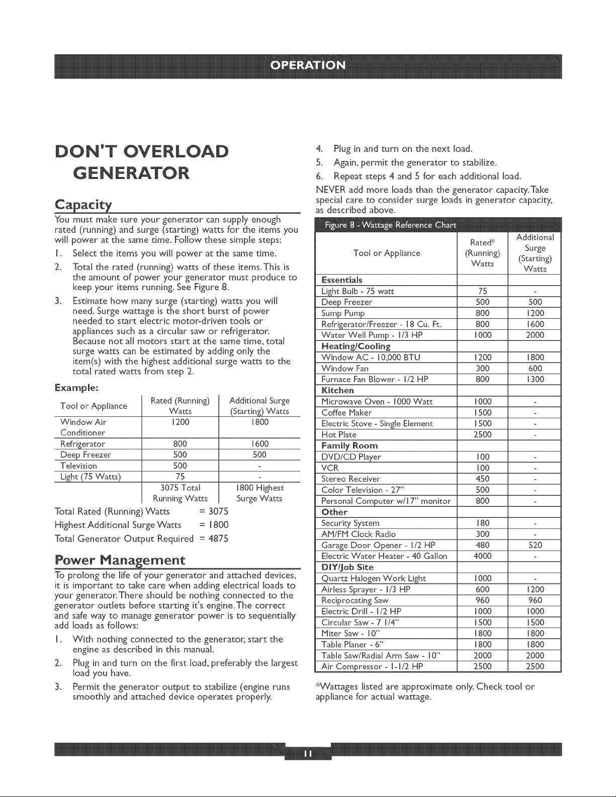
2. Total the rated (running) watts of these items.This is
the amount of power your generator must produce to
keep your items running. See Figure 8.
3. Estimate how many surge (starting) watts you will
need. Surge wattage is the short burst of power
needed to start electric motor-driven tools or
appliances such as a circular saw or refrigerator.
Because not aJJmotors start at the same time, total
surge watts can be estimated by adding only the
item(s) with the highest additional surge watts to the
total rated watts from step 2.
Tool or Appliance
Window Air
Rated (Running)
Watts
1200
Conditioner
Refrigerator
Dee_ Freezer
Television
8OO
5OO
5OO
75
3075 Total
Running Watts
Total Rated (Running)_atts -- 3075
HighestAdditiona[ Surge_atts -- 1800
Total Generator Output Required -- 4875
Power Manasement
To prolong the JJfeof your generator and attached devices,
it is important to take care when adding electrical loads to
your generator.There should be nothing connected to the
generator outlets before starting it's engine.The correct
and safe way to manage generator power is to sequentially
add loads as follows:
I. With nothing connected to the generator, start the
engine as described in this manual.
2. Plug in and turn on the first load, preferably the largest
load you have.
3. Permit the generator output to stabilize (engine runs
smoothly and attached device operates properly.
Additional Surge
(Starting) Watts
1800
1600
5OO
1800 Highest
Surge Watts
4. Plug in and turn on the next load.
5. Again, permit the generator to stabilize.
6. Repeat steps 4 and 5 for each additional load.
NEVER add more loads than the generator capacity.Take
special care to consider surge loads in generator capacity,
as described above.
Rated*
Tool or Appliance (Running) Surge
Watts (Starting)
Essentiams
Light Bulb - 75 watt 75
Deep Freezer 500 500
Sump Pump 800 1200
Refrigerator/Freezer - 18 Cu. Ft. 800 1600
Water Well Pump - 1/3 HP 1000 2000
Neating/Cooming
Window AC - 10,000 BTU 1200 1800
Window Fan 300 600
Furnace Fan Blower- 1/2 HP 800 1300
Kitchen
Microwave Oven - 1000 Watt 1000
Coffee Maker 1500
Electric Stove - Single Element 1500
Hot Plate 2500
FamiRy Room
DVDiCD Player 100
VCR 100
Stereo Receiver 450
Color Television - 27" 500
Personal Computer w/l 7" monitor 800
Other
Security System J80
AM/FM Clock Radio 300
Garage Door Opener - 1/2 HP 480 520
Electric Water Heater - 40 Gallon 4000
DJYtjob Site
Quartz Halogen Work Light JO00
Airless Sprayer - J/3 HP 600 J200
Reciprocating Saw 960 960
Electric Drill - 1/2 HP i 000 i 000
Circular Saw - 7 1/4" 1500 1500
Miter Saw - J0" J800 J800
TaMe Planer - 6" J800 J800
Table Saw/Radia[ Arm Saw - 10" 2000 2000
Air Compressor - i-i/2 HP 2500 2500
%_Tattages listed are approximate only. Check tool or
appliance for actual wattage.
Additional
VVatts
ENGINE TECHNICAL
PRODUCT
INFORMATION
This is a single cylinder, overhead vaIve(OHV), air cooled
engine. [t is a low emissions engine.
In the State of California, Model Series J20000 engines are
certified by the Ca[ffornh Air Resources Board to meet
emissions standards for 125 hours. Such certification does
not grant the purchaser, owner or operator of this engine
any additional warranties with respect to the performance
or operational life of this engine.The engine is warranted
solely according to the product and emissions warranties
stated elsewhere in this manual
Power Ratings
_The power ratings for an individual engine model are
initially developed by starting with SAE (Society of
Automotive Engineers) code J[ 940 (Small Engine Power &
Torque Rating Procedure) (Revision 2002-05). Given both
the wide array of products on which our engines are
placed, and the variety of environmental issues applicable to
operating the equipment, it may be that the engine you
have purchased will not develop the rated horsepower
when used in a piece of power equipment (actual "on-site"
power).This difference is due to a variety of factors
including, but not limited to, the following: differences in
altitude, temperature, barometric pressure, humidity, fuel,
engine lubrication, maximum governed engine speed,
individual engine to engine variability, design of the
particular piece of power equipment, the manner in which
the engine is operated, engine run-in to reduce friction and
clean out of combustion chambers, adjustments to the
valves and carburetor, and other factors.The power ratings
may also be adiusted based on comparisons to other
similar engines utilized in similar applications, and will
therefore not necessarily match the values derived using
the foregoing codes.
SPECIFICATIONS
Generator Specifications
Starting _attage ........................ 5,000 Watts
_attage .............................. 4,000 _atts
Rated AC Load Current:
At 120Voks ........................... 33.3 Amps
Phase .................................... I-phase
Rated Frequency ........................... 60 Hertz
Shipping Weight ............................ 140 Ibs.
Gross _ Horsepower ................. 6.5 at 3600 rpm
Bore .............................. 2.69 in. (68ram)
Stroke ............................. 2.20 in. (56mm)
Displacement ...................... 12.57 in. (206 cc)
SparkPlug
Type: ............ Champion RCI2YC or Equivalent
Set Gap To: ................... O.030inch (0.76ram)
Armature Air Gap: .................... 0.010-0.014 in.
(0.25-0.36mm)
Valve clearance with valve springs installed and piston I/4 in.
(6 mm) past top dead center (check when engine is cold).
Intake .............................. 0.004-0.006 in.
(0.10-0.1S mm)
Exhaust ............................. 0.009-0.01 I in.
(0.23-0.28 mm)
Fuel Capacity ......................... 4 U.S. gallons
Oil Capacity .................... 20 Ounces (.6 Liters)
NOTE: For practical operation, the generator load should
not exceed 85% of rated wattage. Engine gross horsepower
will decrease 3-1/2% for each I,O00 feet (300 meters) above
sea level and 1% for each 10° F (5.6 ° C) above 77 ° F
(25 ° C). It should operate satisfactorily at an angle up to 15°.
GENERAL
R :COMMENDAT[ONS
ReguJar maintenance will improve the performance and
extend the life of the generator. See any authorized dealer
for service.
The generator's warranty does not cover items that have
been subjected to operator abuse or negligence.To receive
fu[Jvalue from the warranty, the operator must maintain
generator as instructed in this manua[.
Some adjustments wiJl need to be made periodically to
properly maintain your generator.
All service and adjustments should be made at [east once
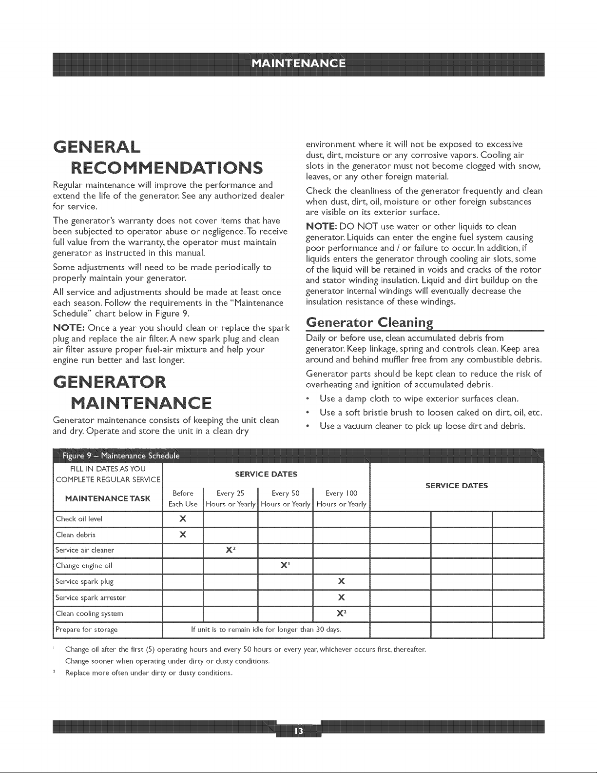
each season. Follow the requirements in the "bqaintenance
Schedule" chart below in Figure 9.
NOTE; Once a year you should clean or replace the spar[4
plug and replace the air fi[ter.A new spar[( plug and dean
air filter assure proper fuebair mixture and help your
engine run better and last longer.
GS:NS:RATOR
MAINTENANCE
Generator maintenance consists of [Keeping the unit clean
and dry. Operate and store the unit in a clean dry
environment where it will not be exposed to excessive
dust, dirt, moisture or any corrosive vapors. Cooling air
slots in the generator must not become dogged with snow,
[eaves,or any other foreign material
Check the cleanliness of the generator frequently and dean
when dust, dirt, oil, moisture or other foreign substances
are visible on its exterior surface.
NOTE: DO NOT use water or other liquids to dean
generator. Liquids can enter the engine fuel system causing
poor performance and / or failure to occur. [n addition, ff
liquids enters the generator through cooling air slots, some
of the liquid will be retained in voids and cracks of the rotor
and stator winding insulation. Liquid and dirt buildup on the
generator internal windings will eventually decrease the
insulation resistance of these windings.
Generator Cleaning
DaJJyor before use, dean accumulated debris from
generator. Keep linkage, spring and controls clean. Keep area
around and behind muffler free from any combustible debris.
Generator parts should be kept dean to reduce the risk of
overheating and ignition of accumulated debris.
o Use a damp cloth to wipe exterior surfaces dean.
o Use a soft brisde brush to loosen caked on dirt, oil etc.
o Use a vacuum cleaner to pick up bose dirt and debris.
FILL IN DATESASYOU
COMPLETE REGULAR SERVICE
MA|NTENANCE TASK
Before Every 25 Every 50 Every 100
SERVICE DATES
EachUse Hours orYearly Hours orYeary HoursorYeady
Check oil level
Clean debris
Service air cleaner
Change engine oil
Service spar[< plug
Service spar[< arrester
Clean cooling system
Prepare for storage
E Change oil after the first (5) operating hours and every 50 hours or every year, whichever occurs first, thereafter,
Change sooner when operating under dirt}" or dust}" conditions,
2 Replace more often under dirt}" or dust}" conditions,
X
X
X2
X _
x
x
x 2
If unit is to remain idle for longer than 30 days,
SERVICE DATES
Use low pressure air (not to exceed 25 psi) to blow
away dirt. Inspect cooling air slots and openings on the
generator.These openings must be kept clean and
unobstructed.
J
DO NOT expose generator to excessive moisture, dust, dirt,
or corrosivevapors.
DO NOT insert any objects through cooling slots.
ENGINE MAINTENANCE
WARN(NG
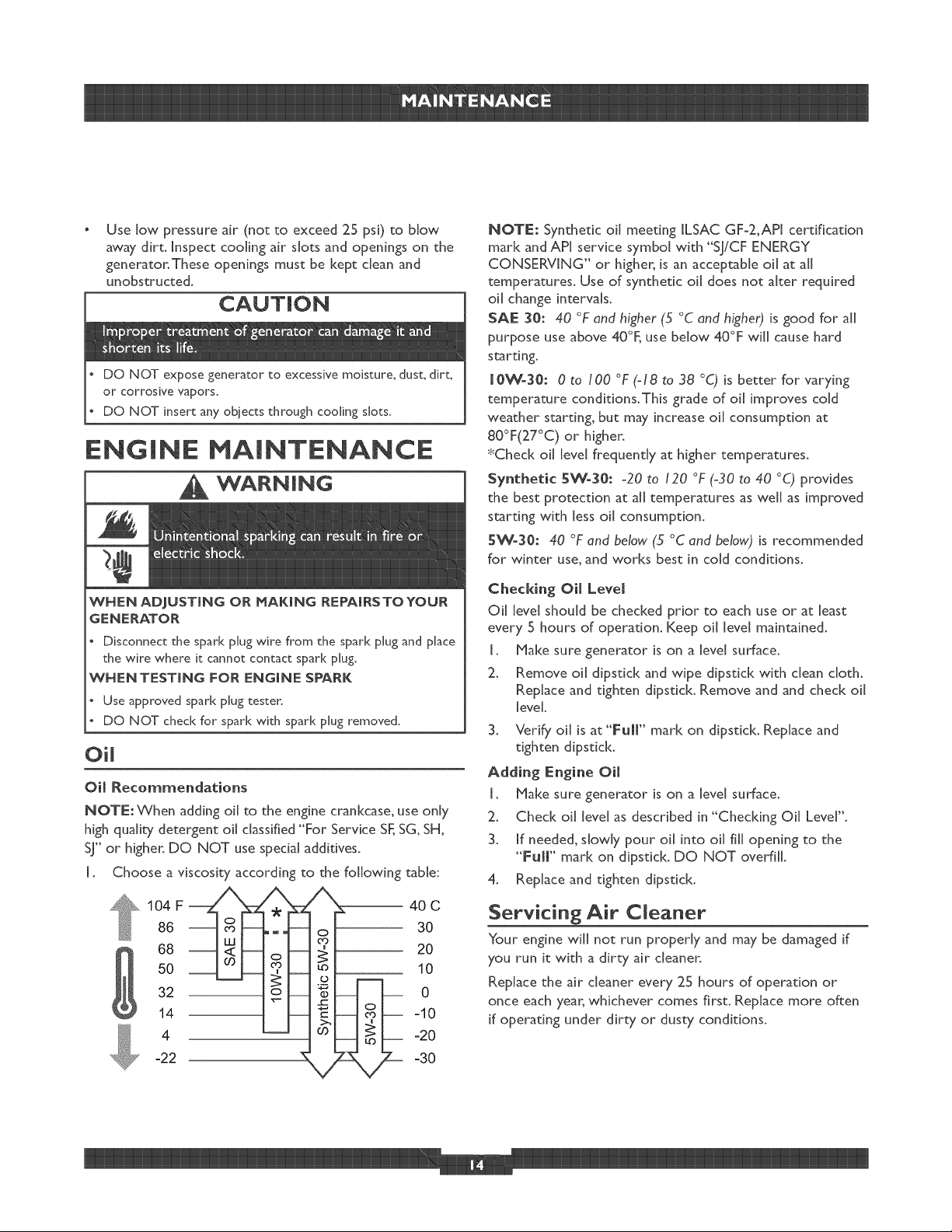
NOTE: Synthetic oil meeting ILSAC GF-2,API certification
mark and API service symbol with "SJiCF ENERGY
CONSERVING" or higher, is an acceptable oil at all
temperatures. Use of synthetic oil does not alter required
oil change intervals.
J
SAE 30:40 °F and higher G °C and higher) is good for all
purpose use above 40°F, use below 40°F will cause hard
starting.
J0Wo30:0 to 100 °F (-18 to 38 °C) is better for varying
temperature conditions.This grade of oil improves cold
weather starting, but may increase oil consumption at
80°F(27°C) or higher.
*Check oil level frequently at higher temperatures.
Synthetic BW-30:-20 to I20 °F (-30 to 40 o© provides
the best protection at all temperatures as well as improved
starting with less oil consumption.
SWo30:40 °F and below (5 °C and below,) is recommended
for winter use, and works best in cold conditions.
WNEN ADJUSTING OR MAKING REPAJRSTOYOUR
GENERATOR
Disconnect the spar[< plug wire from the spar[< plug and place
the wire where it cannot contact spar[< plug.
WNENTESTJNG FOR ENGINE SPARK
Use approved spar[< plug testen
DO NOT check for spark with spark plug removed,
Oil
Oil Recommendations
NOTE: When adding oil to the engine crankcase, use only
high quality detergent oil classified "For Service SF, SG, SH,
SJ" or higher. DO NOT use special additives.
I. Choose a viscosity according to the following table:
104 F
86
68
50
32
14
4
-22
) 30
i
)
40 C
10
0
-10
-20
-30
Checking Oil Level
Oil level should be checked prior to each use or at least
every 5 hours of operation. Keep oil level maintained.
I. Make sure generator is on a level surface.
2. Remove oil dipstick and wipe dipstick with clean cloth.
Replace and tighten dipstick. Remove and and check oil
level.
3. Verify oil is at"Full" marl< on dipstick. Replace and
tighten dipstick.
Adding Engine Oil
I. Make sure generator is on a level surface.
2. Check oil level as described in "Checking Oil Level".
3. If needed, slowly pour oil into oil fill opening to the
°°Full" marl< on dipstid<. DO NOT overfill.
4. Replace and tighten dipstick.
Servicing Air Cleaner
Your engine will not run properly and may be damaged if
you run it with a dirty air cleaner.
Replace the air cleaner every 25 hours of operation or
once each year, whichever comes first. Replace more often
if operating under dirty or dusty conditions.
 Loading...