

Briggs & Stratton 01935 Owner’s Manual
Husqvarna
01935 1365GN
Owner's Manual / Manual del Propietario
_Read this manual carefully and become familiar with your generator.
Know the applications, the limitations and any hazards involved.
_Lea este manual de manera cuidadosa y familiaricese con su generador.
Conozca sus usos, sus limitaciones y cualquier peligro relacionado con el mismo.
0 3 Part Number 531 30 00-69
Safety Rules
TABLE OF CONTENTS
SafetyRules.................................. 2-4
Know Your Generator ........................... 5
Assembly.................................... 6-7
Operation .................................. 8-13
Maintenance.................................. 14
Storage...................................... 15
Notes ....................................... 16
Troubleshooting ............................... 17
Schematic/Wiring Diagram .................... 18-19
Replacement Parts........................... 20-24
Warranty .................................... 25
EQUIPMENT
DESCRIPTION
_Read this manual carefully and become familiar
with your generator. Know the applications, the
limitations and any hazards involved.
This generator is an engine-driven, revolving field,
alternating current (AC) generator.It wasdesignedto
supply electrical power for operating compatible electrical
lighting,appliances,tools andmotor loads.Thegenerator's
revolving field isdriven at about 3,600rpm by a single-
cylinder engine.
SAFETY RULES
A his is the safety alert symbol. It is used to
alert you to potential personal injury hazards.
Obey all safety messages that follow this
symbol to avoid possible injury or death.
The safety alert symbol (_.) isused with a signalword
(DANGER, CAUTION,WARNING), a pictorial and/or a
safety messageto alert you to hazards.DANGER indicates
a hazard which, if not avoided,will result indeath or
serious injury.WARNING indicatesa hazardwhich, if not
avoided,could result in death or serious injury.
CAUTION indicatesa hazardwhich, if not avoided,might
result in minor or moderate injury.CAUTION, when used
without the alert symbol,indicatesasituation that could
result in equipment damage.Follow safety messagesto
avoid or reduce the risk of injuryor death.
WARNING
The engine exhaust from this product contains I
chemicals known to the State of California to cause
cancer, b rth defects, or other reproduct ve harm.
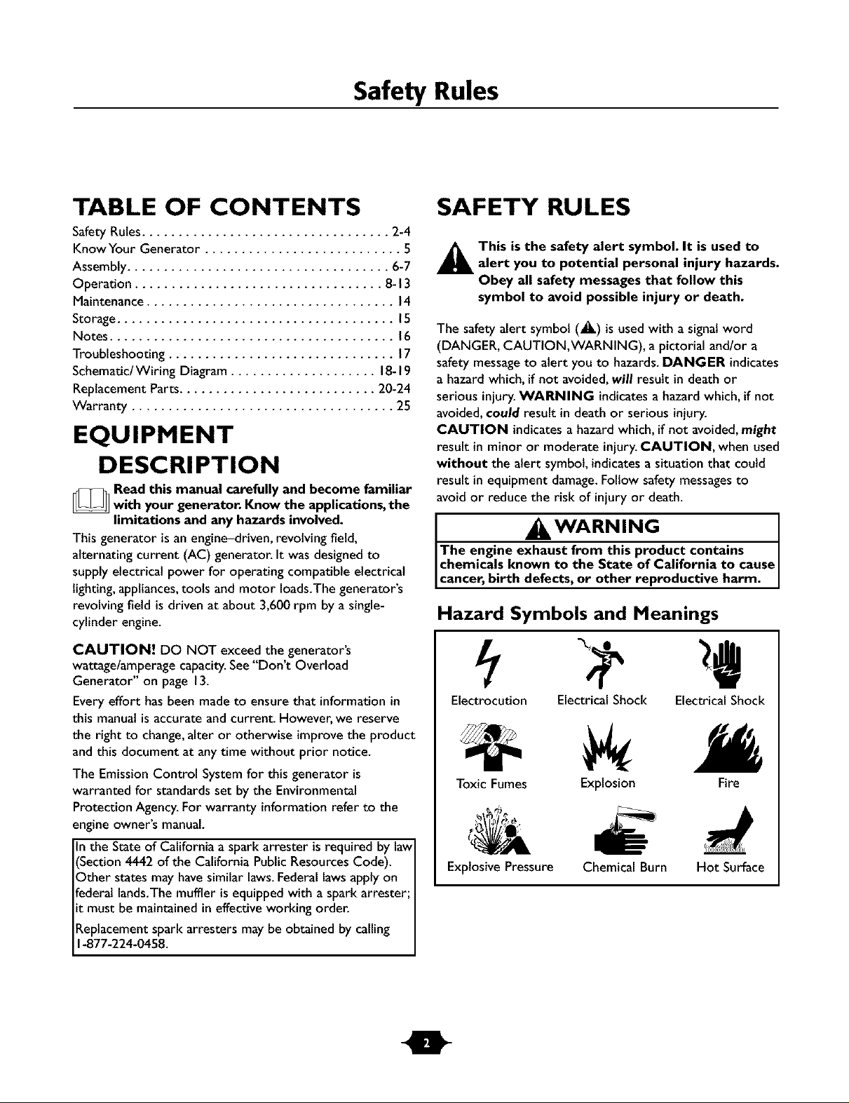
Hazard Symbols and Meanings
CAUTION! DO NOT exceed the generator's
wattage/amperage capacity.See"Don't Overload
Generator" on page 13.
Every effort has been madeto ensure that informationin
this manualisaccurate and current. However,we reserve
the right to change,alter or otherwise improvethe product
and this document at anytime without prior notice.
The Emission Control System for this generator is
warranted for standards set by the Environmental
Protection Agency.For warranty information refer to the
engine owner's manual.
the State of California a spark arrester isrequired by law
Section 4442 of the California PublicResourcesCode).
)ther states may havesimilar laws.Federal lawsapply on
Federallands.Themuffler isequipped with aspark arrester:
t must be maintained ineffective working order.
Replacementspark arresters may be obtained by calling
1-877-224-0458.
Electrocution Electrical Shock Electrical Shock
Toxic Fumes
Explosive Pressure
Explosion Fire
Chemical Burn Hot Surface
Safety Rules
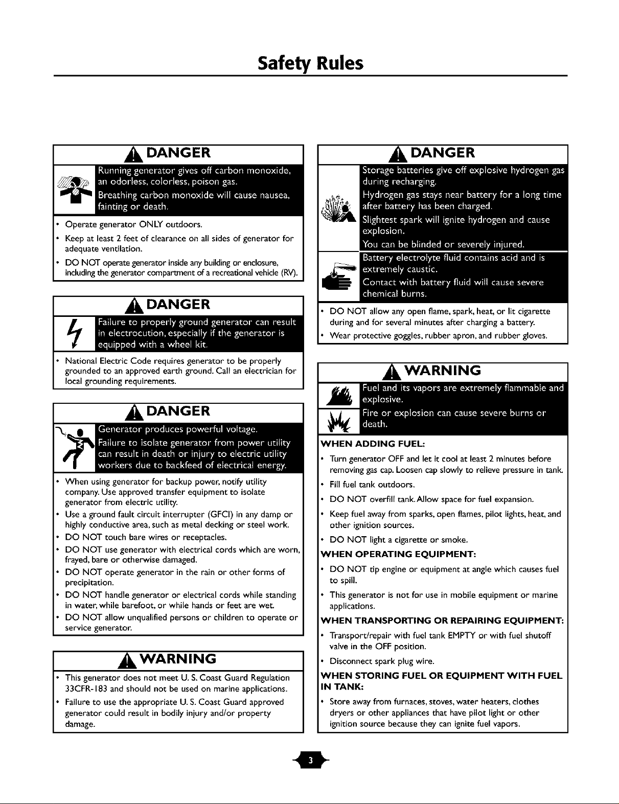
DANGER
Operate generator ONLY outdoors.
Keepat least 2 feet of clearance on all sides of generator for
adequate ventilation.
DO NOT operategenerator insideanybuildingor enclosure,
includingthegenerator compartmentof a recreationalvehicle(RV).
DANGER
National Electric Code requires generator to be properly
grounded to anapproved earth ground. Call an electrician for
localgrounding requirements.
DANGER
When usinggenerator for backuppower, notify utility
company.Use approved transfer equipment to isolate
generator from electric utility.
Use aground fault circuit interrupter (GFCi) inanydamp or
highly conductive area,such as metal decking or steel work.
DO NOT touch bare wires or receptacles.
DO NOT use generator with electrical cords which are worn
frayed,bare or otherwise damaged.
DO NOT operate generator in the rain or other forms of
precipitation.
DO NOT handle generator or electrical cords while standing
inwater, while barefoot, or while hands or feet are wet.
DO NOT allow unqualified persons or children to operate or
service generator.
IKWARNING
Thisgenerator does not meet U. S.Coast Guard Regulation
33CFR-183and should not be used on marine applications.
Failureto use the appropriate U.S.Coast Guard approved
generator could result in bodily injury and/or property
damage.
DANGER
DO NOT allow any open flame, spark, heat,or lit cigarette
during andfor several minutes after charginga battery.
Wear protective goggles,rubber apron, and rubber gloves.
WARNING
WHEN ADDING FUEL:
Turn generator OFF and let it cool at least 2 minutes before
removing gas cap. Loosen cap slowly to relieve pressure in tank_
Fill fuel tank outdoors.
DO NOT overfill tank.Allow space for fuel expansion.
Keep fuel away from sparks, open flames, pilot lights, heat, and
other ignition sources.
DO NOT light a cigarette or smoke.
eVHEN OPERATING EQUIPMENT:
DO NOT tip engine or equipment at angle which causes fuel
to spill.
This generator is not for use in mobile equipment or marine
applications.
'HEN TRANSPORTING OR REPAIRING EQUIPMENT:
Transportlrepair with fuel tank EMPTY or with fuel shutoff
valve in the OFF position.
Disconnect spark plug wire.
eVHEN STORING FUEL OR EQUIPMENT WITH FUEL
IN TANK:
Store away from furnaces, stoves, water heaters, clothes
dryers or other appliances that have pilot light or other
ignition source because they can ignite fuel vapors.
Safety Rules
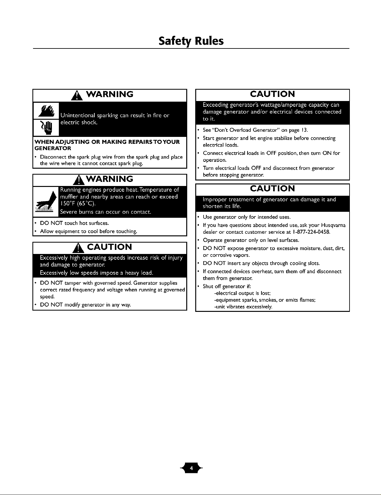
WARNING
;ENERATOR
Disconnect the spark plug wire from the spark plug and place
the wire where it cannot contact spark plug.
, WARNING
DO NOT touch hot surfaces.
Allow equipment to cool before touching.
CAUTION
DO NOT tamper with governed speed.Generator supplies
correct rated frequency and voltage when running at governed
speed.
DO NOT modify generator in any way.
CAUTION
See"Don't Overload Generator" on page 13.
Start generator and let engine stabilize before connecting
electrical loads.
Connect electrical loads in OFF position, then turn ON for
operation.
Turn electrical loads OFF and disconnect from generator
before stopping generator.
CAUTION
Use generator onlyfor intended uses.
tf you have questions about intended use,askyour Husqvarna
dealer or contact customer service at 1-877-224-0458.
Operate generator only on level surfaces.
DO NOT expose generator to excessive moisture, dust, dirt,
or corrosive vapors.
DO NOT insertany objects through cooling slots.
tf connected devices overheat, turn them off and disconnect
them from generatoc
Shut off generator if.'
-electrical output is lost;
-equipment sparks,smokes,or emits flames;
-unit vibrates excessively.
Features and Controls
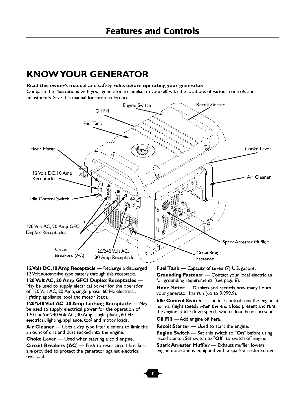
KNOWYOUR GENERATOR
Read this owner's manual and safety rules before operating your generator.
Compare the illustrations with your generator, to familiarize yourself with the locations of various controls and
adjustments. Save this manual for future reference.
OilFill
FuelTank
Engine Switch Recoil Starter
Choke Lever
12Volt DC,10Amp
Receptacle
Idte Control Switch
120Volt AC, 20 Amp GFCI
Duplex Receptacles
Circuit
Breakers (AC)
12Volt DC, I0 Amp Receptacle -- Rechargeadischarged
12Volt automotive type battery through this receptacle.
120Volt AC, 20 Amp GFCI Duplex Receptacles --
May be usedto supplyelectrical power for the operation
of 120VoltAC, 20 Amp, single phase,60 Hz electrical,
lighting,appliance,tool and motor loads.
120/240 Volt AC, 30 Amp Locking Receptacle -- May
be usedto supply electrical power for the operation of
120and/or 240Vott AC, 30Amp, single phase,60 Hz
electrical, lighting,appliance,tool and motor loads.
Air Cleaner -- Uses a dry type filter element to limit the
amount of dirt and dust suckedinto the engine.
Choke Lever -- Used when starting a cold engine.
Circuit Breakers (AC) -- Pushto reset circuit breakers
are provided to protect the generator againstelectrical
overload.
120/240Volt AC,
30Amp Receptacle
Air Cleaner
Spark Arrester Muffler
Grounding
Fastener
FuelTank -- Capacity of seven (7) U.S.galtons.
Grounding Fastener -- Contact your local electrician
for grounding requirements (see page8).
Hour Meter -- Displaysand records how many hours
your generator hasrun (up to 9,999.9).
Idle Control Switch --The idle control runs the engineat
normal (high) speedswhen there isa load present and runs
the engineat idle (low) speedswhen a load is not present.
Oil Fill --Add engineoil here.
Recoil Starter-- Used to start the engine.
Engine Switch -- Set this switch to "On" before using
recoil starter. Set switch to "Off" to switch off engine.
Spark Arrester Muffler -- Exhaust muffler lowers
engine noise and isequipped with a spark arrester screen.
Assembly
ASSEMBLY
Your generator requires some assembly and isready for
use after it hasbeen properly serviced with the
recommended oil and fuel.
If you have any problems with the assembly of your
generator, please call the generator helpline at
1-877-224-0458.
Remove Generator From Carton
I. Set carton on a rigid fiat surface with "This Side Up"
arrows pointing upward.
2. Carefully open top flapsof shippingcarton.
3. Cut down corners at one end of carton from top to
bottom and laythat side of carton down fiat
4. Removeall packing material, carton fillers, etc.
5. Removegenerator from shipping carton.
Carton Contents
Check all contents. If any parts are missingor damaged,call
the generator helpline at 1-877-224-0458.
The generator
Generator and engine owner's manuals
Locking 30 Amp plug
Battery chargecables
Engineoil
Wheel kit
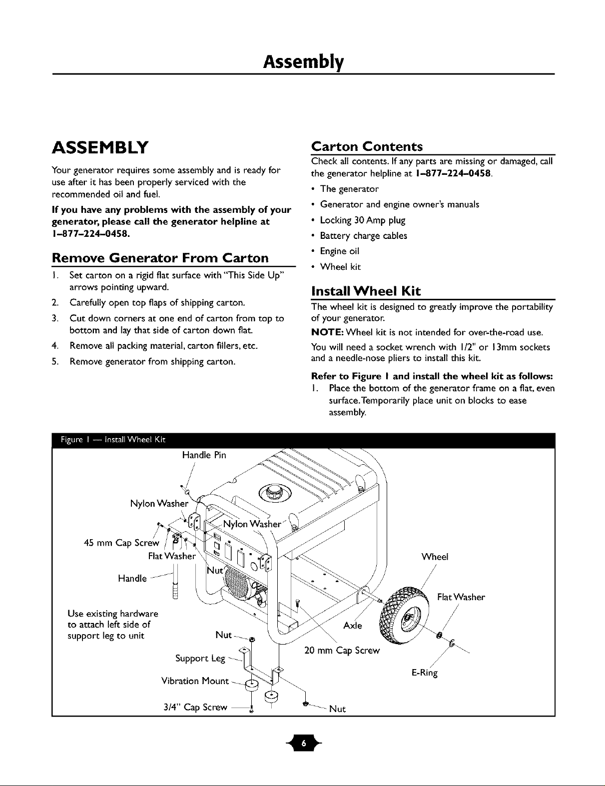
Install Wheel Kit
The wheel kit is designedto greatly improvethe portability
of your generator.
NOTE: Wheel kit is not intendedfor over-the-road use.
You will need a socket wrench with I/2" or 13mm sockets
and a needle-nose pliers to install this kit.
Refer to Figure I and install the wheel kit as follows:
I. Placethe bottom of the generator frame on a fiat, even
surface.Temporarily place unit on blocks to ease
assembly.
Nylon Washer
45 mm Ca
Handle
Use existing hardware
to attach left side of
support legto unit
Handle Pin
Flat Washer
Nut
20 mm Cap Screw
Vibration Mount
3/4" Cap Screw Nut
Wheel
FlatWasher
Axle
/
E-Ring
Assembly
2. Slide axle through both axle mounting brackets on
cradle frame, as shown in Figure I.
3. Slide a wheel over the axle.
NOTE: Be sure to install both wheels with the air
pressure valve on the outboard side.
4. Placethe e-ring onto the groove in the axle.You may
add the fiat washer if desired.
NOTE: Use retaining pins insteadof e-clip, if applicable.
5. Placeone end of the needle nose pliers on the bottom
of the axle and the other end of the pliers on top of
the e-ring.Seatthe e-ring by pressing the pliers closed.
6. Repeat step 3 through 5 to secure second wheel.
7. Removethe temporary blocks.
8. Attach the vibration mounts to the support leg with
3/4" capscrewsand lock nuts.
9. To aid support legassembly,rest generator on cradle,
engine end down. Removethe existing hardware from
the left unit vibrationmount with 13mmwrench. Use
the samehardware to attach the support leg.
10. Attach the other side of the support legwith a 20 mm
cap screw and lock nut. Restgenerator on wheels and
support leg.
I I. Attach handlesto handle brackets on generator frame,
as shown in Figure I,with 45 mm capscrews,flat
washers,nylon washers,and lock nuts.
12. Loop handle pins to generator frame as shown in
Figure I. Raise handles and insert handle pins to move
generator.
13. Check eachfastener to ensure it is secure and the
tires are inflated between 15-40 PSI.
BEFORE STARTING THE
ENGINE
Add Engine Oil and Fuel
• Placegenerator on a levelsurface.
• Refer to engineowner's manualand follow oil and fuel
recommendations and instructions.
CAUTION
• Refer to engine manualfor oil andfuel fill information.
• Damage to equipment resulting from failure to follow this
instruction will void warranty.
NOTE: Check oil often during enginebreak-in. Refer to
engine owner's manualfor recommendations.
NOTE:The generator assemblyrotates on a pretubricated
and sealed baitbearing that requires no additional
lubricationfor the life of the bearing.
Operation
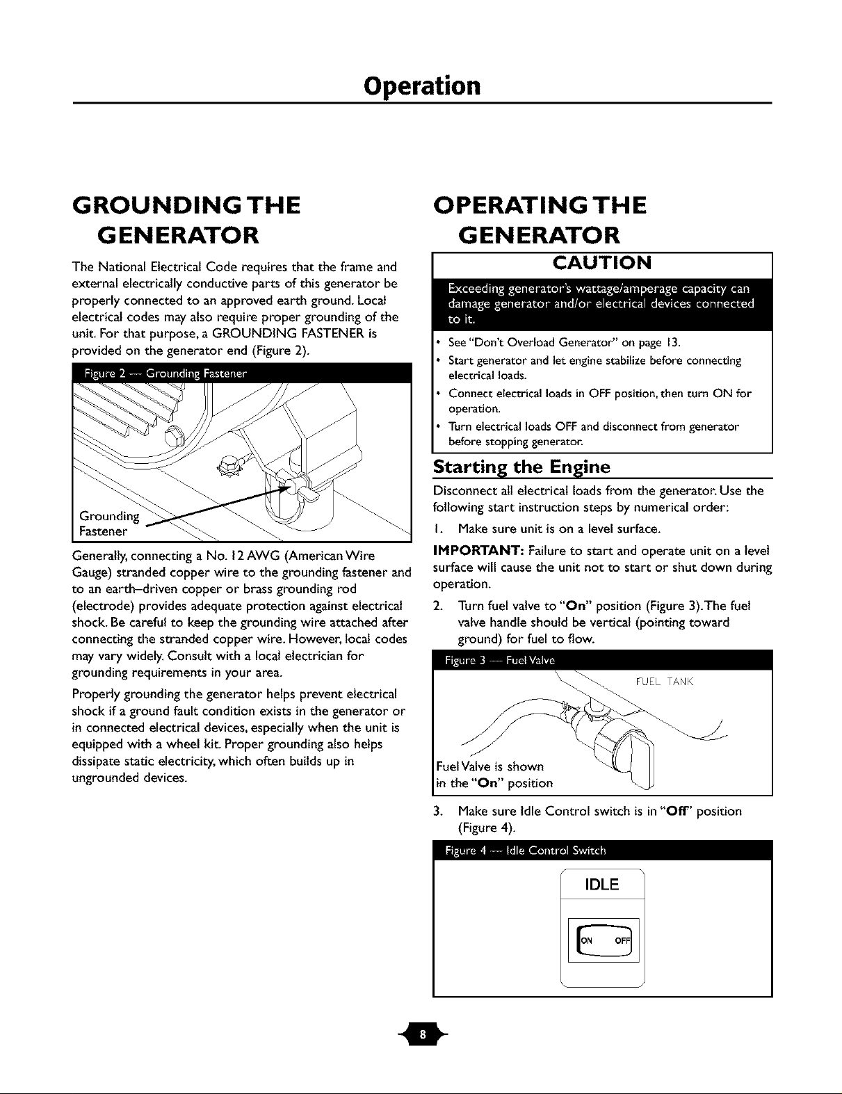
GROUNDING THE
G EN ERATO R
The National Electrical Code requires that the frame and
external electrically conductive parts of this generator be
properly connected to anapproved earth ground. Local
electrical codes mayalso require proper grounding of the
unit. For that purpose, a GROUNDING FASTENERis
provided on the generator end (Figure 2).
Fastener
Generally,connecting aNo. 12AWG (American Wire
Gauge) stranded copper wire to the grounding fastener and
to anearth-driven copper or brassgrounding rod
(electrode) provides adequate protection against electrical
shock. Be careful to keepthe grounding wire attached after
connecting the stranded copper wire. However, local codes
may vary widely. Consult with alocalelectrician for
grounding requirements in your area.
Properly grounding the generator helpsprevent electrical
shock if aground fault condition exists in the generator or
in connected electrical devices,especiallywhen the unit is
equipped with a wheel kit. Proper grounding also helps
dissipate static electricity, which often buildsup in
ungrounded devices.
OPERATING THE
G EN ERATO R
CAUTION
See"Don't Overload Generator" on page 13.
Start generator and let engine stabilize before connecting
electrical loads.
Connect electrical loads in OFF position, then turn ON for
operation.
Turn electrical loads OFF and disconnect from generator
before stopping generator.
Starting the Engine
Disconnectall electrical loads from the generator. Use the
following start instructionsteps by numerical order:
I. Make sure unit is on a levelsurface.
IMPORTANT: Failureto start and operate uniton a level
surface will causethe unit not to start or shut down during
operation.
2. Turn fuel valve to "On" position (Figure 3).The fuel
valve handle should be vertical(pointing toward
ground) for fuel to flow.
Fuel Valve is shown
in the "On" position
3. Make sure Idle Control switch is in"Off" position
(Figure 4).
I_ImE_L_Ill [IL_l _"_a
IDLE
Operation
4. Start engine according to instructions given in engine
owner's manual
NOTE: If engine starts after 3 pulls but failsto run, or if
unit shutsdown during operation, make sure unit is on a
level surface and check for proper oll level in crankcase.
This unit may be equipped with a low oil protection device.
See engine manual.
Connecting Electrical Loads
• Let engine stabilize and warm up for afew minutes after
starting.
• Plugin and turn on the desired 120and/or 240VottAC,
single phase,60 Hz electrical loads.
• DO NOT connect 240Vott loads to the 120Volt duplex
receptacles.
• DO NOT connect 3-phase loads to the generator.
• DO NOT connect 50 Hz loads to the generator.
• DO NOT OVERLOADTHE GENERATOR. See
"Don't Overload Generator" on page 13.
Stopping the Engine
I. Unplug ALL electrical loadsfrom generator panel
receptacles.NEVER start or stop engine with electrical
devices plugged in and turned ON.
2. Move idle control switch to "Off" position.
3. Let engine run at no-load for several minutes to
stabilize internal temperatures of engine and generator.
4. Turn engine off according to instructions given in the
engine owner's manual.
5. Move fuel valve to "Off" position.
Operating Automatic Idle Control
This switch isdesigned to greatly improvefuel economy.
When this switch is turned ON, the enginewill only
run at its normal high governed engine speed when an
electrical load is connected.When an electrical load is
removed,the enginewill run at a reduced speed.With the
switch off, the engine will run at the normal highengine
speed.Always have the switch off when starting and
stopping the engine.
Charging a Battery
Your generator hasthe capability of recharging a discharged
12Volt automotive or utility style storage battery. DO
NOT use the unit to chargeany 6Volt batteries. DO NOT
usethe unit to crank an engine having a discharged battery.
DANGER
DO NOT allow any open flame, spark, heat,or lit cigarette
during andfor several minutes after charginga battery.
Wear protective goggles,rubber apron, and rubber gloves.
To recharge 12Volt batteries, proceed as follows:
I. Check fluid levelin all battery cells.If necessary,add
ONLY distilled water to cover separators in battery
cells.DO NOT use tap water.
2. If battery isequipped with vent caps,make sure they
are installedand are tight.
3. If necessary,clean battery terminals.
4. Connect battery charge cable connector plug to panel
receptacle identifiedby the words "12-VOLTS D.C".
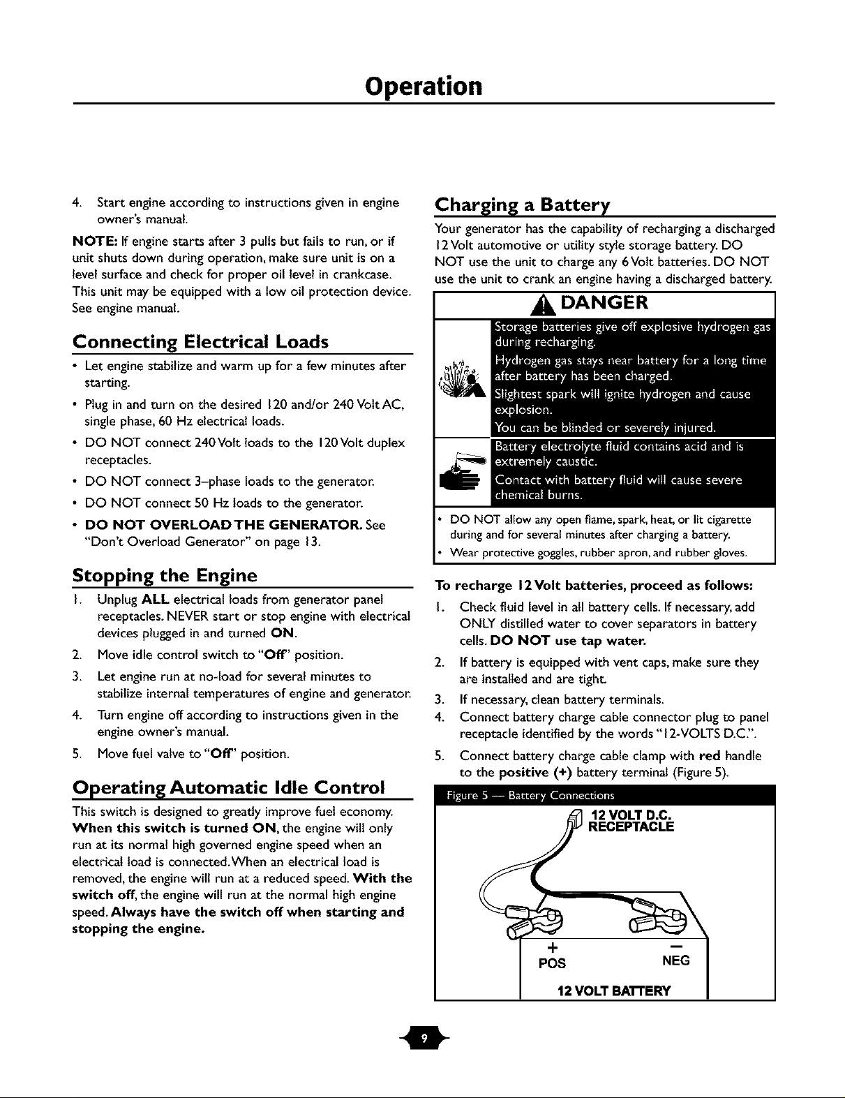
5. Connect battery charge cable clamp with red handle
to the positive (+) battery terminal (Figure5).
12 VOLT D.C.
RECEPTACLE
+
POS NEG
12 VOLT BA'R'ERY
Operation
6. Connect battery chargecable clamp with black handle
to the negative (-) battery terminal (Figure5).
7. Start engine.Let engine run while battery recharges.
8. When battery hascharged,shut down engine
NOTE: Use an automotive hydrometer to test battery
state of charge and condition. Follow the hydrometer
manufacturer's instructionscarefully.Generally,a battery is
considered to be at 100%state of chargewhen specific
gravity of itsfluid (as measured by hydrometer) is 1.260or
higher.
COLD WEATH ER
OPERATION
Under certain weather conditions (temperatures below
40°F [4°C] and a high dew point), your generator may
experience icingof the carburetor and/or the crankcase
breather system.
Build a structure that wilt enclose three sidesand the top
of the generator:
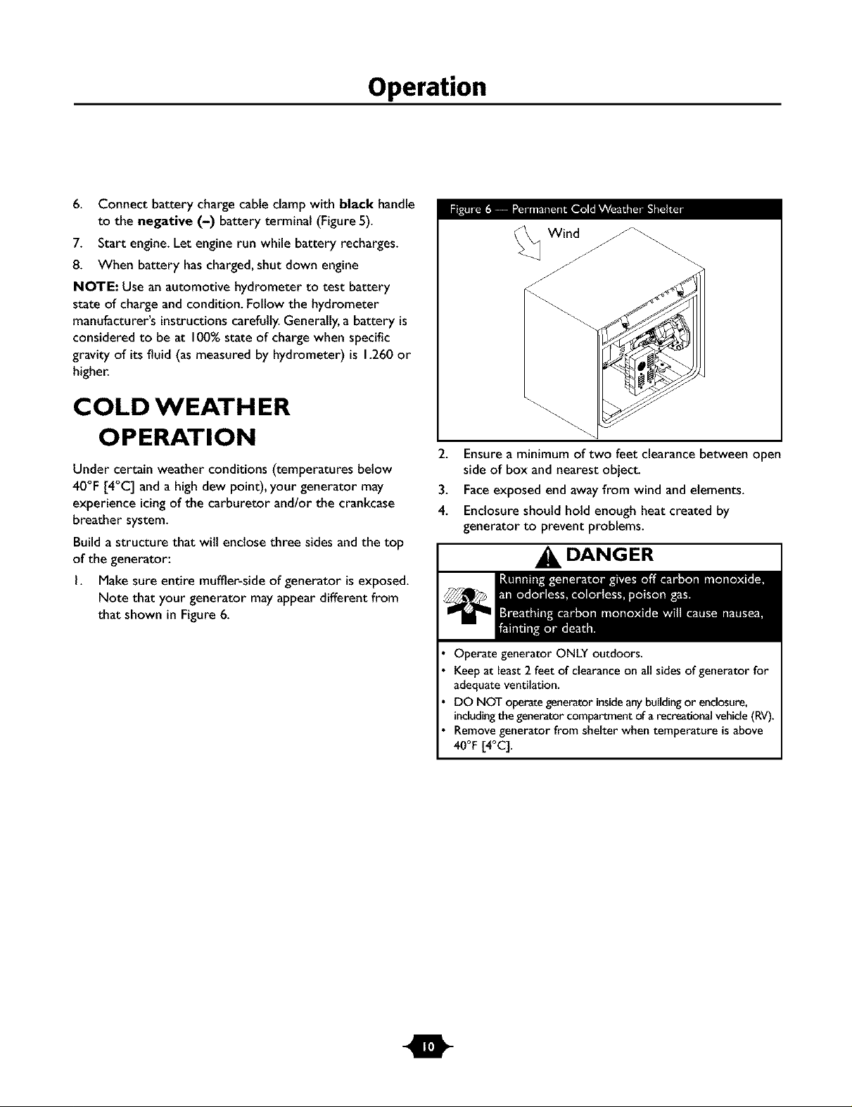
I. Make sure entire muffler-side of generator is exposed.
Note that your generator mayappear different from
that shown in Figure 6.
Wind
2. Ensure a minimum of two feet clearance between open
side of box and nearest object.
3. Face exposed end away from wind and elements.
4. Enclosure should hold enough heat created by
generator to prevent problems.
DANGER
m
OperategeneratorONLYoutdoors.
Keepat least2 feet of clearanceon all sidesof generatorfor
adequateventilation.
DO NOT operategeneratorinsideanybuildingor enclosure,
includingthegeneratorcompartmentof arecreationalvehicle(RV).
Removegeneratorfrom shelterwhentemperatureisabove
40°F[4°q.
Operation
RECEPTACLES
CAUTION
NEVERattempt to power a device requiring more amperage
than generator or receptacle can supply.
DO NOT overload the generator. See"Don't Overload
Genera_r'.
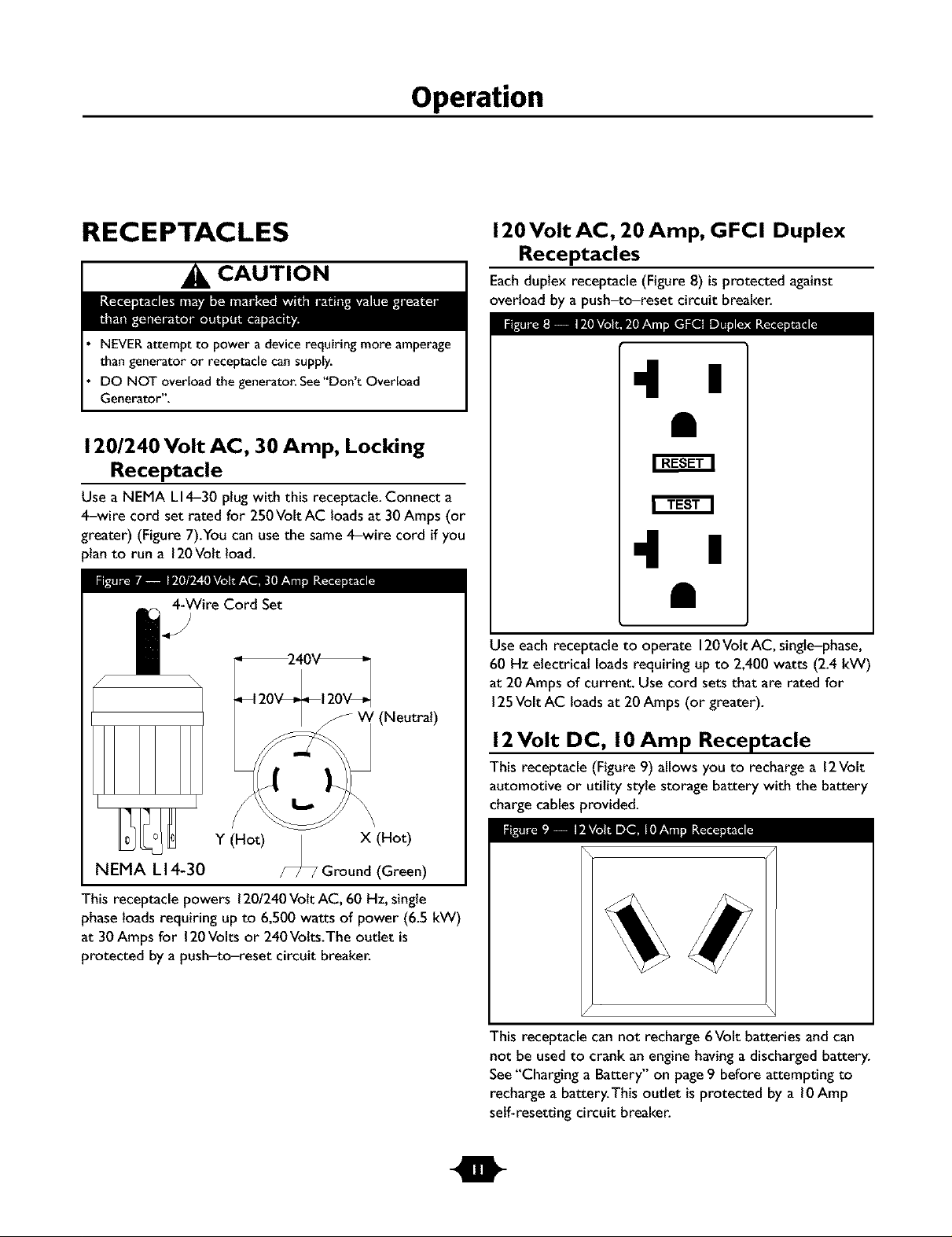
120/240 Volt AC, 30 Amp, Locking
Receptacle
Use a N EMA LI4-30 plug with this receptacle.Connect a
4-wire cord set rated for 250Volt AC loads at 30 Amps (or
greater) (Figure7).You can usethe same 4-wire cord if you
)lan to run a 120Volt load.
4-WireCord Set
/-
' (Neutral)
Y (Hot) | X (Hot)
NEMA L 14-30 /-_ Ground (Green)
120 Volt AC, 20 Amp, GFCI Duplex
Receptacles
Eachduplex receptacle (Figure 8) is protected against
overload by a push-to-reset circuit breaker.
_:I P_tkv_ e* • • , " , m
•l I
•l I
Use each receptacle to operate 120Volt AC, single-phase,
60 Hz electrical loadsrequiring up to 2,400 watts (2.4 kW)
at 20Amps of current. Usecord sets that are rated for
125Volt AC loads at 20Amps (or greater).
12Volt DC, I 0 Amp Receptacle
Thisreceptacle (Figure 9) allows you to recharge a 12Volt
automotive or utility style storage battery with the battery
chargecables provided.
IPE_ _ 1[*TA_m
This receptacle powers 1201240Volt AC, 60 Hz,single
phaseloadsrequiring upto 6,500 watts of power (6.5 kW)
at 30 Amps for 120Volts or 240Volts.The outlet is
protected bya push-to-reset circuit breaker.
Thisreceptacle can not recharge 6Volt batteries and can
not be used to crank an engine having a discharged battery.
See"Charging a Battery" on page9 before attempting to
recharge a battery.This outlet isprotected by a l0 Amp
self-resetting circuit breaker.
I
Operation
Ground Fault Protection
This unit is equipped with a Ground Fault Circuit
Interrupter (GFCI).This device meets applicablefederal,
state and local codes.
The GFCI protects againstelectrical shock that may be
caused if your body becomes a path which electricity
travels to reach the ground.This could happen if you touch
a "Live" appliance or wire, or are touching plumbing or
other materials that connect to the ground.
When protected by a GFCI, one maystill feel a shock, but
the GFCIshould cut current off quickly enough so that a
person in normal health should not suffer any serious
electrical injury.
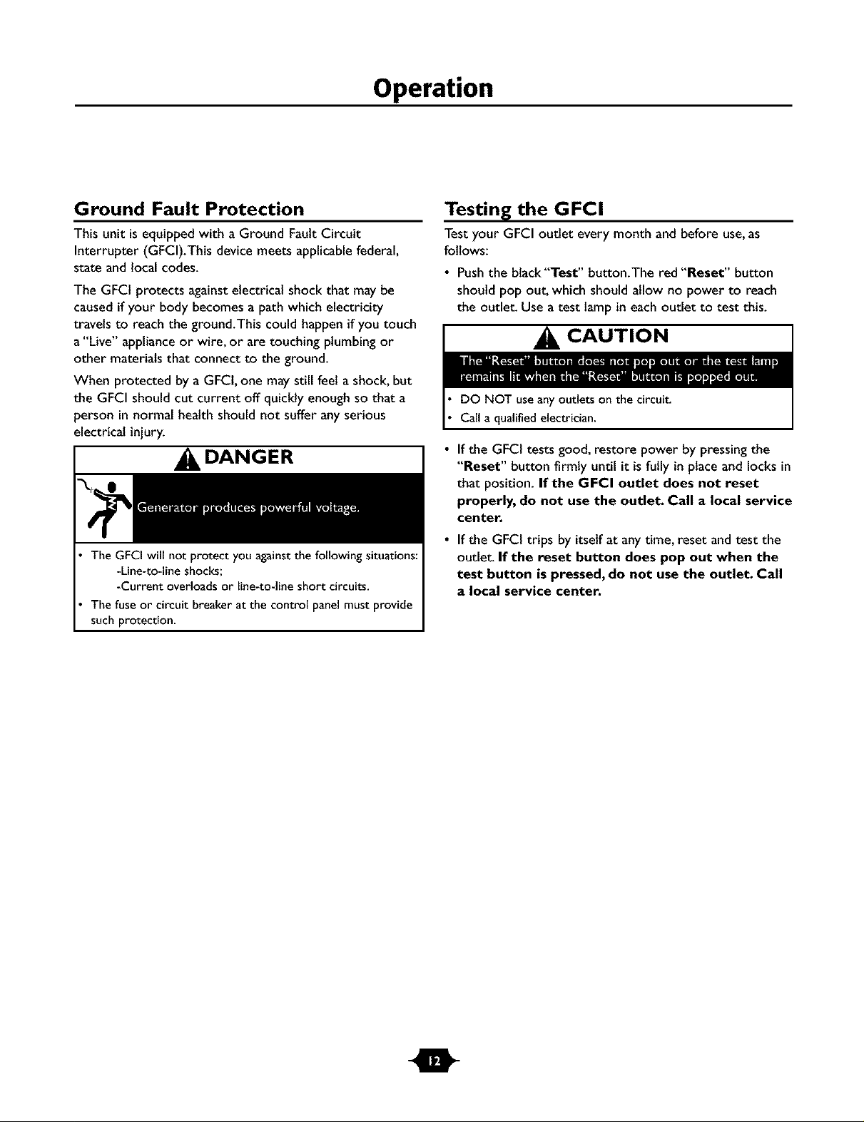
DANGER
The GFCI will not protect you againstthe following situations:
-Line-to-line shocks;
-Current overloads or line-to-line short circuits.
The fuse or circuit breaker at the control panel must provide
such protection.
Testing the GFCI
Testyour GFCI outlet every month and before use,as
follows:
• Pushthe black"Test" button.The red "Reset" button
should pop out, which should allow no power to reach
the outlet. Use a test lamp in each outlet to test this.
CAUTION
DO NOT useanyoutletson the circuit.
Callaqualifiedelectrician.
If the GFCI tests good, restore power by pressingthe
"Reset" button firmly until it is fully in placeand locks in
that position. If the GFCI outlet does not reset
properly, do not use the outlet. Call a local service
center.
If the GFCI trips by itself at anytime, reset and test the
outlet. If the reset button does pop out when the
test button is pressed, do not use the outlet. Call
a local service center.
m
 Loading...