

Page 1

Parts ManualParts ManualParts ManualParts Manual
Mfg. No: 1696741-00
1222EE, B&S 11.5 Gross TP 22" Single
Copyright © Briggs and Stratton. All Rights reserved
12-Mar-2019
Page 2

Page 3

Table Of ContentsTable Of ContentsTable Of ContentsTable Of Contents
Model ComponentsModel ComponentsModel ComponentsModel Components PagePagePagePage
Auger Drive Group. . . . . . . . . . . . . . . . . . . . . . . . . . . . . . . . . . . . . . . . . . . . . . . . . . . . . . . . . . . . . . . . . . . . . . . . . . . . . . . . . . . . 4
Auger Group. . . . . . . . . . . . . . . . . . . . . . . . . . . . . . . . . . . . . . . . . . . . . . . . . . . . . . . . . . . . . . . . . . . . . . . . . . . . . . . . . . . . . . . . . 6
Chute Group - Electric. . . . . . . . . . . . . . . . . . . . . . . . . . . . . . . . . . . . . . . . . . . . . . . . . . . . . . . . . . . . . . . . . . . . . . . . . . . . . . . . . 8
Chute Rotation Group - Electric. . . . . . . . . . . . . . . . . . . . . . . . . . . . . . . . . . . . . . . . . . . . . . . . . . . . . . . . . . . . . . . . . . . . . . . . . 10
Decals Group. . . . . . . . . . . . . . . . . . . . . . . . . . . . . . . . . . . . . . . . . . . . . . . . . . . . . . . . . . . . . . . . . . . . . . . . . . . . . . . . . . . . . . . . 12
Engine Group. . . . . . . . . . . . . . . . . . . . . . . . . . . . . . . . . . . . . . . . . . . . . . . . . . . . . . . . . . . . . . . . . . . . . . . . . . . . . . . . . . . . . . . . 14
Frame Group. . . . . . . . . . . . . . . . . . . . . . . . . . . . . . . . . . . . . . . . . . . . . . . . . . . . . . . . . . . . . . . . . . . . . . . . . . . . . . . . . . . . . . . . . 16
Handles & Controls Group - Electric. . . . . . . . . . . . . . . . . . . . . . . . . . . . . . . . . . . . . . . . . . . . . . . . . . . . . . . . . . . . . . . . . . . . . 18
Light Panel Group. . . . . . . . . . . . . . . . . . . . . . . . . . . . . . . . . . . . . . . . . . . . . . . . . . . . . . . . . . . . . . . . . . . . . . . . . . . . . . . . . . . . . 20
Wheel & Body Covering Group. . . . . . . . . . . . . . . . . . . . . . . . . . . . . . . . . . . . . . . . . . . . . . . . . . . . . . . . . . . . . . . . . . . . . . . . . 22
Torque Specification Chart. . . . . . . . . . . . . . . . . . . . . . . . . . . . . . . . . . . . . . . . . . . . . . . . . . . . . . . . . . . . . . . . . . . . . . . . . . . . . 24
Not For
Reproduction
Copyright © Briggs and Stratton. All Rights reserved
3 12-Mar-2019
Page 4

Auger Drive GroupAuger Drive GroupAuger Drive GroupAuger Drive Group
Mfg. No: 1696741-00Note: Unless noted otherwise, use the standard torque specifications
Not For
Reproduction
Copyright © Briggs and Stratton. All Rights reserved
4 12-Mar-2019
Page 5

Auger Drive GroupAuger Drive GroupAuger Drive GroupAuger Drive Group
REF NOREF NOREF NOREF NO PART NOPART NOPART NOPART NO QTYQTYQTYQTY DESCRIPTIONDESCRIPTIONDESCRIPTIONDESCRIPTION
0010 707379 1 PULLEY, Driven
0020 1739179YP 1 PULLEY, Driver
0030 1739526YP 1 ARM, Idler, Drive
0040 1502120MA 1 IDLER, Plastic Ball Bearing
0050 1739338YP 1 BELT, Drive
0060 703406 1 CAPSCREW, Hex Head, 3/8-16 x 1-1/2
0070 703117 1 NUT, Nylock, 3/8
0080 1739709YP 1 SPACER, Idler Arm
0090 1931318SM 1 BOLT, Carriage, Short Neck, 1/4-20 x 7/8 G5
0100 7091253YP 1 WASHER, Flat, .281 X 3/4 x 1/2
0110 703232 1 NUT, Nylock, 1/4
0120 1502113MA 1 CABLE, Handle
0130 1739935YP 1 BOOT, Clutch Spring
0140 1750226YP 1 SPRING, Idler
0150 1750315YP 1 SPRING, Extension
0160 1750329YP 1 BRACKET, Cable Guide
0170 704130 2 SCREW, Hex Washer Head, 1/4-20 x 1/2
0180 1750594YP 1 CAPSCREW, Hex Shoulder, 1/4 x 3/4
0190 703937 1 NUT, Locking, #10
0200 579860MA 1 SPOOL CABLE, Auger Control
0210 001X20MA 1 CAPSCREW, Hex Head, 3/8-24 x 1
0220 706162 1 WASHER, Locking, 3/8
0240 703826 1 RETAINER, Pushnut, 1/4
Not For
Reproduction
Copyright © Briggs and Stratton. All Rights reserved
5 12-Mar-2019
Page 6
Auger GroupAuger GroupAuger GroupAuger Group
Mfg. No: 1696741-00Note: Unless noted otherwise, use the standard torque specifications
Not For
Reproduction
Copyright © Briggs and Stratton. All Rights reserved
6 12-Mar-2019
Page 7

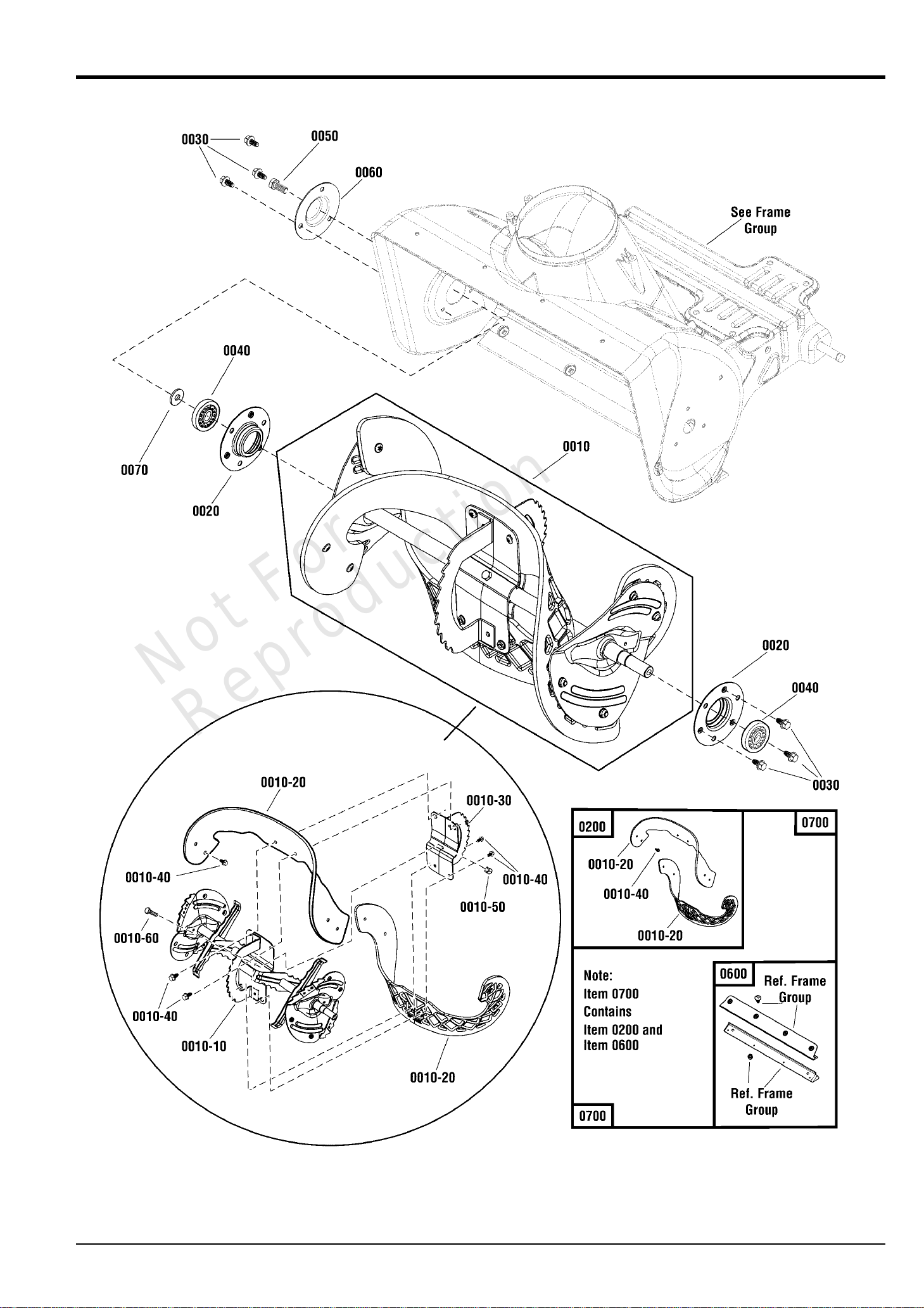
Auger GroupAuger GroupAuger GroupAuger Group
REF NOREF NOREF NOREF NO PART NOPART NOPART NOPART NO QTYQTYQTYQTY DESCRIPTIONDESCRIPTIONDESCRIPTIONDESCRIPTION
0010 1687814 1 AUGER ASSEMBLY, Complete
-(Incl. Ref. Nos. 0010-10, 0010-20, 0010-30, 0010-40, 0010-50 & 0010-60)
0010-10 ----- 1 * AUGER SHAFT ASSEMBLY
0010-20 ----- 2 ** FLIGHT, Auger
-(Included with Ref. No. 0200)
0010-30 ----- 2 * PLATE, Auger, Center
0010-40 770003 12 SCREW, Pan Head Torx, 1/4-20 x 3/4
-(Included with Ref. No. 0200)
0010-50 703232 1 NUT, Nylock, 1/4-20
0010-60 703234 1 CAPSCREW, Hex Head, 1/4-20 X 1 1/2, G5
0020 1739228YP 2 RETAINER, Bearing
0030 704130 6 SCREW, Hex Washer Head, Trilob, 1/4-20 x 1/2
0040 1705897SM 2 BEARING, Ball, 11/16 x 1-9/16 x 15/32
0050 704287 1 CAPSCREW, Hex Head, 5/16-18 x 3/4
0060 1739229AYP 1 CAP, BEARING
0070 703118 1 WASHER, Flat, 7/8 x 21/64
0200 1687804 1 KIT, AUGER FLIGHT
-(Incl. Ref. Nos. 0030 & 0010-40)
0600 1687805 1 KIT, Scraper Bar
-(Reference Frame group)
0700 1687806 1 KIT, Scraper Bar & Flight
-(Incl. Ref. Nos. 0200 & 0600)
Not ForNot ForNot ForNot For
ReproductionReproductionReproductionReproduction
Footnotes:Footnotes:Footnotes:Footnotes:
Note: ** Not a servicable part, order Auger Flight Kit.
Note: * Not a servicable part, order complete Auger Assembly.
Copyright © Briggs and Stratton. All Rights reserved
7 12-Mar-2019
Page 8

Chute Group - ElectricChute Group - ElectricChute Group - ElectricChute Group - Electric
Mfg. No: 1696741-00Note: Unless noted otherwise, use the standard torque specifications
Not For
Reproduction
Copyright © Briggs and Stratton. All Rights reserved
8 12-Mar-2019
Page 9

Chute Group - ElectricChute Group - ElectricChute Group - ElectricChute Group - Electric
REF NOREF NOREF NOREF NO PART NOPART NOPART NOPART NO QTYQTYQTYQTY DESCRIPTIONDESCRIPTIONDESCRIPTIONDESCRIPTION
0010 1751006YP 1 PARTS BAG
0010-20 1751399YP 3 SCREW, Hex Washer Head, HI-LO, 1/4-15 x 1-1/4
0020 1739522YP 1 CHUTE ASSEMBLY
Not For
Reproduction
Copyright © Briggs and Stratton. All Rights reserved
9 12-Mar-2019
Page 10

Chute Rotation Group - ElectricChute Rotation Group - ElectricChute Rotation Group - ElectricChute Rotation Group - Electric
Mfg. No: 1696741-00Note: Unless noted otherwise, use the standard torque specifications
Not For
Reproduction
Copyright © Briggs and Stratton. All Rights reserved
10 12-Mar-2019
Page 11

Chute Rotation Group - ElectricChute Rotation Group - ElectricChute Rotation Group - ElectricChute Rotation Group - Electric
REF NOREF NOREF NOREF NO PART NOPART NOPART NOPART NO QTYQTYQTYQTY DESCRIPTIONDESCRIPTIONDESCRIPTIONDESCRIPTION
0010 706509 1 GEAR, Chute Rotation
0020 706510 1 PLATE, Chute Mounting
0030 ----- 3 RETAINER, Chute
0040 7091594SM 1 PIN, Cotter, 1/2
0050 1739309YP 1 MOTOR, Chute Rotation
0060 1739621YP 3 SCREW, Torx Button Head, M5 x .8 x 14
0070 703054 3 SCREW, Hex Washer Head, 1/4-20 x 5/8
0080 706512 1 GEAR, 10T
0090 706513 1 GEAR, 19T
0100 706514 1 SCREW, Shoulder Button Washer Head, 1/4-20 x 1.00
0110 703463 1 NUT, Nylock Flanged, 1/4-20
0120 706516 2 SCREW, High-Low, 1/4-15 x 1.00
0130 7091552SM 3 WASHER, Flat, 1/4
0140 7024649YP 1 WIRE TIE,11 Inch Standard Black Nylon
Not For
Reproduction
Copyright © Briggs and Stratton. All Rights reserved
11 12-Mar-2019
Page 12

Decals GroupDecals GroupDecals GroupDecals Group
Mfg. No: 1696741-00Note: Unless noted otherwise, use the standard torque specifications
Not For
Reproduction
Copyright © Briggs and Stratton. All Rights reserved
12 12-Mar-2019
Page 13

Decals GroupDecals GroupDecals GroupDecals Group
REF NOREF NOREF NOREF NO PART NOPART NOPART NOPART NO QTYQTYQTYQTY DESCRIPTIONDESCRIPTIONDESCRIPTIONDESCRIPTION
0010 1739966YP 1 DECAL, Chute, FR/ENG
0020 1737865YP 1 DECAL, Danger, Chute, FR/ENG
0030 1739970YP 1 DECAL, Step 1-2-3
0040 1750734YP 1 DECAL, 4 Start, FR/ENG
0050 1750736YP 1 DECAL, 5 Start, FR/ENG
0060 1739977YP 1 DECAL, Bail Engagement
0070 770589 1 DECAL, Briggs & Stratton, 1222EE
0090 770590 2 DECAL, Briggs & Stratton
0130 1754247YP 1 DECAL, Assembled in USA
0190 706788 1 DECAL, Briggs & Stratton Logo
Not For
Reproduction
Copyright © Briggs and Stratton. All Rights reserved
13 12-Mar-2019
Page 14

Engine GroupEngine GroupEngine GroupEngine Group
Mfg. No: 1696741-00Note: Unless noted otherwise, use the standard torque specifications
Not For
Reproduction
Copyright © Briggs and Stratton. All Rights reserved
14 12-Mar-2019
Page 15

Engine GroupEngine GroupEngine GroupEngine Group
REF NOREF NOREF NOREF NO PART NOPART NOPART NOPART NO QTYQTYQTYQTY DESCRIPTIONDESCRIPTIONDESCRIPTIONDESCRIPTION
0010 15C107-0003-F8 1 * ENGINE, 11.5TP Briggs & Stratton
-(Engine Model: 15C107-0003-F8)
0010 15C107-0014-F8 1 * ENGINE, 11.5TP Briggs & Stratton
-(Engine Model: 15C107-0014-F8)
0010-10 793193 1 GUARD, Muffler, Wire
0010-20 699854 3 SCREW, Muffler Guard, Hex Washer Head
0010-30 ----- 1 ** STARTER, 110V
0020 1750032YP 1 HOUSING, Starter, 110V
0030 704130 1 SCREW, Hex Washer Head, Trilob, 1/4-20 x 1/2
0040 1750593YP 2 SCREW, Pan Head Phillips, Plast., 8-16 x 2-1/8
0050 032618MA 4 STRAP, Tie
Not ForNot ForNot ForNot For
ReproductionReproductionReproductionReproduction
Footnotes:Footnotes:Footnotes:Footnotes:
Note** See your local Briggs & Stratton distributor for parts and service.
Note* To verify your specific engine model, please reference the ID Tag located on your engine. See your local Briggs & Stratton distributor for parts and service.
Copyright © Briggs and Stratton. All Rights reserved
15 12-Mar-2019
Page 16

Frame GroupFrame GroupFrame GroupFrame Group
Mfg. No: 1696741-00Note: Unless noted otherwise, use the standard torque specifications
Not For
Reproduction
Copyright © Briggs and Stratton. All Rights reserved
16 12-Mar-2019
Page 17

Frame GroupFrame GroupFrame GroupFrame Group
REF NOREF NOREF NOREF NO PART NOPART NOPART NOPART NO QTYQTYQTYQTY DESCRIPTIONDESCRIPTIONDESCRIPTIONDESCRIPTION
0010 1756280AYP 1 FRAME ASSEMBLY
0020 1739100BMYP 1 HOUSING, Drive
0030 1752876YP 2 CAPSCREW, Hex Head, 5/16-24 x 5/8
0035 1917356SM 2 WASHER, Lock Helical Spring
0040 2828635SM 3 SCREW, Taptite, 3/8-16 X 1 1/4
0050 1739555YP 1 CHIMNEY
-Used without Service Kit 1687864, Refer to Chute Rotation Group
0050 707849 1 CHIMNEY
-Used with Service Kit 1687864, Refer to Chute Rotation Group
0060 1750444YP 5 SCREW, Hi-Low, 1/4-15 x 3/4
0070 ----- 1 SCRAPER BAR
-(Included with Ref. No. 0600)
0075 1752660AYP 1 SUPPORT, Scraper Blade
-(Included with Ref. No. 0600)
0080 ----- 4 SCREW, 1/4-20 x 5/8, Allen Head
-(Included with Ref. No. 0600)
0110 1752935YP 4 NUT, 1/4-20, Nylon Hex, CZ
-(Included with Ref. No. 0600)
0600 1687805 1 KIT, Scraper Bar
-(Includes Ref. Nos. 0070, 0075, 0080, 0110, Auger Flights & Hardware)
Not For
Reproduction
Copyright © Briggs and Stratton. All Rights reserved
17 12-Mar-2019
Page 18

Handles & Controls Group - ElectricHandles & Controls Group - ElectricHandles & Controls Group - ElectricHandles & Controls Group - Electric
Mfg. No: 1696741-00Note: Unless noted otherwise, use the standard torque specifications
Not For
Reproduction
Copyright © Briggs and Stratton. All Rights reserved
18 12-Mar-2019
Page 19

Handles & Controls Group - ElectricHandles & Controls Group - ElectricHandles & Controls Group - ElectricHandles & Controls Group - Electric
REF NOREF NOREF NOREF NO PART NOPART NOPART NOPART NO QTYQTYQTYQTY DESCRIPTIONDESCRIPTIONDESCRIPTIONDESCRIPTION
0010 703949 4 SCREW, Hex Washer Head, Taptite, 5/16-18 x 5/8
0020 770051 1 HANDLEBAR, Lower
0030 705750 1 HANDLEBAR, Upper
0040 1739361BNYP 1 BAIL, Engine Stop
0050 703059 2 BOLT, Carriage, Curved Head, 5/16 x 2, G2
0060 7105085YP 2 KNOB, Handle
0070 1739389YP 1 GUIDE, Rope
0080 703232 1 NUT, 1/4
Not For
Reproduction
Copyright © Briggs and Stratton. All Rights reserved
19 12-Mar-2019
Page 20

Light Panel GroupLight Panel GroupLight Panel GroupLight Panel Group
Mfg. No: 1696741-00Note: Unless noted otherwise, use the standard torque specifications
Not For
Reproduction
Copyright © Briggs and Stratton. All Rights reserved
20 12-Mar-2019
Page 21

Light Panel GroupLight Panel GroupLight Panel GroupLight Panel Group
REF NOREF NOREF NOREF NO PART NOPART NOPART NOPART NO QTYQTYQTYQTY DESCRIPTIONDESCRIPTIONDESCRIPTIONDESCRIPTION
0010 708157 1 PANEL
0020 1736176YP 1 HEADLIGHT ASSEMBLY
-(Includes Ref. Nos. 0020-10, 0020-20, 0020-40 & 0020-50)
0020-10 1736177YP 1 LENS, Twin Light
0020-20 1736178YP 1 DEFLECTOR
0020-40 1736180YP 2 SOCKET & GASKET ASSEMBLY, Headlight
0020-50 1736181YP 2 BULB, HEADLIGHT 12V 15W (1156)
0030 706481 1 COVER, Light Panel
0040 7091105YP 7 SCREW, Hex Washer Head, #10-16 x 1/2
0050 703232 3 NUT, Nylock, 1/4
0060 708701 3 SCREW, Allen Head, 1/4-20 X 1.5
0070 708158 1 WIRING HARNESS
0080 1754865YP 1 SWITCH, Chute Rotation
0090 7024649YP 4 WIRE TIE, 11 Inch Std Black Nylon
Not For
Reproduction
Copyright © Briggs and Stratton. All Rights reserved
21 12-Mar-2019
Page 22

Wheel & Body Covering GroupWheel & Body Covering GroupWheel & Body Covering GroupWheel & Body Covering Group
Mfg. No: 1696741-00Note: Unless noted otherwise, use the standard torque specifications
Not For
Reproduction
Copyright © Briggs and Stratton. All Rights reserved
22 12-Mar-2019
Page 23

Wheel & Body Covering GroupWheel & Body Covering GroupWheel & Body Covering GroupWheel & Body Covering Group
REF NOREF NOREF NOREF NO PART NOPART NOPART NOPART NO QTYQTYQTYQTY DESCRIPTIONDESCRIPTIONDESCRIPTIONDESCRIPTION
0010 770586 1 COVER, Top
0020 770587 1 COVER, Drive Case, Black
0025 770588 1 COVER, Side
0030 1750777YP 1 CAPSCREW, Hex Washer Head, 1/4 x 20 x 2
0040 703232 2 NUT, Nylock, 1/4
0050 7091081SM 2 SCREW, 1/4-15X3/4, Self-Tapping, BZ
0060 704130 7 SCREW, Hex Washer Head, Trilob,1/4-20 x 1/2
0070 311237YP 2 WHEEL, 2 x 8, Plastic 1/2
0100 703179 2 PUSHNUT, 1/2
0120 770056 2 CLIP NUT
0130 708735 1 COVER, Chute Moisture
0150 316042MA 1 SCREW, Hex Washer Head, #10-HL x 5/8
Not For
Reproduction
Copyright © Briggs and Stratton. All Rights reserved
23 12-Mar-2019
Page 24

in/lbs
ft/lbs
3
Torque Specification Chart
FOR STANDARD METRIC MACHINE HARDWARE (Tolerance ± 20%)
Property
Class
Class 8.8
Class 10.9
Class 12.9
Size Of
Hardware
Nm. Nm. Nm.
Nm.
M3 1.28
2.90
5.75
9.9
16.5
24
48
83
132
200
275
390
530
375
995
1350
1830
2360
3050
13.44 1.80
4.10
8.10
14
23
34
67
117
185
285
390
550
745
960
1400
1900
2580
3310
4290
19.2 22.92 2.15
M4 30.72 43.44 52.56 4.95
M5 60.96 5.97 7.15
16.5
9.7
M6 7.3 10.3 12.1
M7 12.1 16.9 19.9
27
M8 17.7
25
29
40
M10 35 50
59
81
M12 61 86.2 103 140
M14
101
136 162 220
M16 147 210 250 340
M18 202 287 346 470
M20 290 405 486 660
M22 390 559 656 890
M24 497
708
840 1140
M27 733 1032 1239 1680
M30 995 1401 1681 2280
M33
1349
1902 2278 3090
M36 1740 2441
3798
2935 3980
M39 2249 3163
Torque Specification Chart
FOR STANDARD MACHINE HARDWARE (Tolerance ± 20%)
Hardware
Grade
SAE Grade 2 SAE Grade 5 SAE Grade 8
Size Of
in/lbs
ft/lbs
in/lbs
ft/lbs
in/lbs
ft/lbs
in/lbs in/lbs
Hardware ft/lbs Nm. ft/lbs Nm. ft/lbs Nm.
8-32 19 2.1 30 3.4 41 4.6
8-36 20 2.3 31 3.5 43 4.9
10-24 27 3.1 43 4.9 60 6.8
10-32 31 3.5 49 5.5 68 7.7
1/4-20 66 7.6 8 10.9 12 16.3
1/4-28 76 8.6 10 13.6 14 19.0
5/16-18 11 15.0 17 23.1 25 34.0
5/16-24 12 16.3 19 25.8 29 34.0
3/8-16 20 27.2 30 40.8 45 61.2
3/8-24 23 31.3 35 47.6 50 68.0
7/16-14 30 40.8 50 68.0 70 95.2
7/16-20 35 47.6 55 74.8 80 108.8
1/2-13 50 68.0 75 102.0 110 149.6
1/2-20 55 74.8 90 122.4 120 163.2
9/16-12 65 88.4
110 149.6 150 204.0
9/16-18 75 102.0 120 163.2 170 231.2
5/8-11 90 122.4 150 204.0 220 299.2
5/8-18 100 136 180 244.8 240 326.4
3/4-10 160 217.6 260 353.6 386 525.0
3/4-16 180 244.8 300 408.0 420 571.2
7/8-9 140 190.4 400 544.0 600 816.0
7/8-14 155 210.8 440 598.4 660 897.6
1-8 220 299.2 580 788.8 900 1,244.0
1-12 240 326.4 640 870.4 1,000 1,360.0
Hex Head Capscrew
Hex Nut
Lockwasher
Washer
Carriage Bolt
NOTES
1. These torque values are to be used for all hardware
excluding: locknuts, self-tapping screws, thread forming
screws, sheet metal screws and socket head setscrews.
2. Recommended seating torque values for locknuts:
a. for prevailing torque locknuts - use 65% of grade 5
torques.
b. for flange whizlock nuts and screws - use 135% of
grade 5 torques.
3. Unless otherwise noted on assembly drawings, all torque
values must meet this specification.
Hardware Identification & Torque Specifications
Common Hardware Types
No
Marks
The guides and ruler furnished below are designed to
help you select the appropriate hardware.
8.8
10.9
12.9
Class 5.6
5.6
5150
13.44
1.28
5.88
26.4
2.50
44.64
4.3
5.2
7.1
7.7
10.5
15
21
988
1340
759
1030
590
800
435
590
320
435
217
295
169
230
126
171
89
121
64
88
42
58
26
36
.56
Thread
Diameter (mm)
Screw, 1/2- 16 x 2
Body
Diameter
Diameter
Inside
Diameter (in)
Nut, 1/2-16
0
1/4 3/4
1/2
21
1/4 3/4
1/2
1/4 3/4
1/2
1/4 3/4
1/2
4
90
100
70
80
50
60
30
40
010
20
Thread
Diameter (mm)
Nut, M8
Screw, M8- 1.25 x 25
Distance between
threads (mm)
Body
Length (in)
Body
Length (mm)
3/8” Bolt or Nut
Wrench—9/16”
5/16” Bolt or Nut
Wrench—1/2”
1/4” Bolt or Nut
Wrench—7/16”
1/2” Bolt or Nut
Wrench—3/4”
7/16” Bolt or Nut
Wrench (Bolt)—5/8”
Wrench (Nut)—11/16”
in/lbs
Threads
per inch
Threads
per inch
Body Length
Body
When a washer or nut is identified as
1/2”
(M8), this is
the Nominal size, meaning the inside diameter is 1/2 inch
(8mm metric thread diameter); if a second number is present
it represents the threads per inch (distance between threads).
When bolt or capscrew is identified as
1/2 - 16 x 2” (M8 - 1.25 x 50),
this means the Nominal size, or body diameter is 1/2 inch (8mm
metric thread diameter), the second number,16, represents the
threads per inch, (distance between threads). The final number
is the body length of the bolt or screw, 2 inches (50mm).
Standard Hardware Sizing
M6 Bolt or Nut
Wrench—10mm
M8 Bolt or Nut
Wrench—13mm
M10 Bolt or Nut
Wrench—17mm
M12 Bolt or Nut
Wrench—19mm
M14 Bolt or Nut
Wrench—22 mm
Wrench & Fastener Size Guide
Page 25

Copyright © Briggs and Stratton. All Rights reserved
12-Mar-2019
 Loading...