

Page 1

Not for
Reproduction
Outdoor Portable Generator
Operator’s Manual
Model Number _____________________________
Revision __________________________________
Serial Number ______________________________
Date Purchased ____________________________
Copyright © 2018. Briggs & Stratton Corporation
Milwaukee, WI, USA. All rights reserved.
800-743-4115
BRIGGSandSTRATTON.COM
Manual No. 80079367 Revision -
Page 2

Not for
Reproduction
Equipment Description
Table of Contents
Equipment Description.........................2
Features and Controls .........................5
Operation....................................7
Maintenance ................................12
Storage ....................................15
FCC Compliance Statement ...................15
Troubleshooting/Specifications .................16
Warranty ...................................18
Register Your Product
To ensure prompt and complete warranty coverage, register
your product online at www.onlineproductregistration.com.
Symbols and Meanings
Signal Meaning
DANGER
WARNING
CAUTION
NOTICE
Symbol Name Explanation
Indicates a hazard which, if not avoided, will
result in death or serious injury.
Indicates a hazard which, if not avoided, could
result in death or serious injury.
Indicates a hazard which, if not avoided, could
result in minor or moderate injury.
Indicates information considered important, but
not hazard-related.
Safety Alert
Symbol
Operator’s
Manual
Toxic Fumes
Fire
Electric
Shock
Indicates a potential personal injury
hazard.
Failure to follow warnings,
instructions and operator’s manual
could result in death or serious
injury.
Engine exhaust contains carbon
monoxide, a poisonous gas that
will kill you in minutes. You cannot
smell it or see it.
Fuel and its vapors are extremely
flammable which could cause
burns or fire resulting in death or
serious injury.
Engine exhaust could cause fire
resulting in death or serious injury.
Generator could cause electrical
shock resulting in death or serious
injury.
WARNING! This product can expose you to
chemicals including gasoline engine exhaust,
which is known to the State of California to cause
cancer, and carbon monoxide, which is known to the State
of California to cause birth defects or other reproductive
harm. For more information go to www.P65Warnings.ca.gov.
Equipment Description
Read this manual carefully and become familiar
with your outdoor generator. Know its applications,
its limitations, and any hazards involved. Save
these instructions for future reference.
The outdoor generator is an engine-driven, revolving
field, alternating current (AC) generator equipped with
a voltage regulator. The generator is designed to supply
electrical power for operating compatible electrical lighting,
appliances, tools and motor loads. The voltage regulator
within the generator is designed to automatically maintain
output voltage level.
The portable generator can be used to power outdoor
items using extension cords or to restore home power
using a transfer switch. A transfer switch is a separate
device installed by a licensed electrician that allows the
portable generator to be cord connected, using the locking
receptacle, directly into your home’s electrical system.
Install a listed transfer switch as soon as possible if
generator will be used to provide home power restoration.
Every effort has been made to ensure that the information
in this manual is both accurate and current. However,
the manufacturer reserves the right to change, alter or
otherwise improve the generator and this documentation at
any time without prior notice.
NOTICE If you have questions about intended use, contact
an authorized service dealer. This equipment is designed to
be used with Briggs & Stratton® authorized parts only.
System Ground
The generator has a system ground that connects the
generator frame components to the ground terminals on the
AC output receptacles. The system ground is connected to
the AC neutral wire (the neutral is bonded to the generator
frame).
Special Requirements
There may be Federal or State regulations, local codes, or
ordinances that apply to the intended use of the generator.
Please consult a qualified electrician, electrical inspector, or
the local agency having jurisdiction.
This generator is not intended to be used at a construction
site or similar activity as defined by NFPA 70-2017 (NEC)
section 590.6.
Hot Surface
Muffler could cause burns or
resulting in serious injury.
EN2 BRIGGSandSTRATTON.COM
Page 3
Not for
Reproduction
Equipment Description
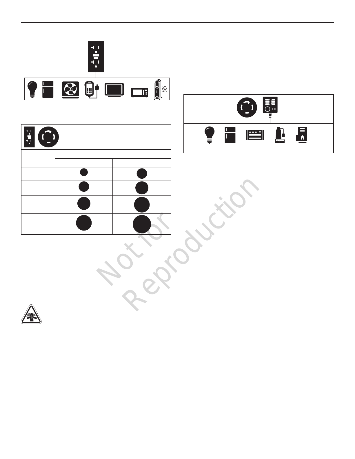
To Restore Power Using Extension Cords
120V
OUTLET
1. Only use grounded cords marked for outdoor use
rated for your loads.
To provide power using
Total
Amperage
Up to 13A
Up to 15A
Up to 20A
extension cords
Minimum Guage, Outdoor Rated
Up to 50 FT (15 M) Up to 100 FT (30 M)
16
14
12
14
12
10
To Restore Home Power Using a Listed
Transfer Switch
Connections to your home’s electrical system must use a
listed* transfer switch installed by a licensed electrician.
The connection must isolate the generator power from
the utility power and comply with all applicable laws and
electrical codes. Power your home with a 30 Amp transfer
switch system.
120/240V
Outlet
Typical Indoor Items
—
Transfer
Switch
Up to 30A
2. Follow cord safety instructions.
3. Install carbon monoxide alarm(s).
4. When operating generator with extension cords, make
sure it is located in an open, outdoor area, at least 20
ft. (6.1 m.) from occupied spaces with exhaust pointed
away.
5. Extension cords running directly into home, powering
indoor items IS NOT RECOMMENDED.
DANGER! Engine exhaust contains carbon
monoxide, a poisonous gas that will kill you in
minutes. You cannot smell it, see it, or taste it.
Even if you do not smell exhaust fumes, you could still be
exposed to carbon monoxide gas.
• Extension cords running directly into the home
increase your risk of carbon monoxide poisoning
through openings.
• If an extension cord running directly into the home is
used to power indoor items, the operator recognizes
that this increases the risk of CO poisoning to people
inside the home and assumes that risk.
6. Install a listed* transfer switch as soon as possible
if generator will be used to provide home power
restoration.
10
8
* Certified by a Nationally Recognized Testing Laboratory
that the product complies to appropriate product safety test
standards.
EN3
Page 4

Not for
Reproduction
Equipment Description
Choke Control
Engine Identification
Oil Fill Cap/Dipstick
Oil Drain Plug
Grounding Fastener
Fuel Cap
Fuel Valve
Spark Arrester Muffler/Exhaust
Recoil Starter
Air Cleaner
Identification Label
Air Cleaner — Filters engine intake air.
Choke Control — Used when starting a cold engine.
Engine Identification — Provides model, type and code of
engine.
Fuel Cap — Add unleaded fuel here.
Fuel Valve — Used to turn fuel supply on and off to engine.
Grounding Fastener — Consult your local agency having
jurisdiction for grounding requirements in your area.
Identification Label — Provides model and serial number of
generator.
Oil Drain Plug — Drain engine oil here.
Oil Fill Cap/Dipstick — Check and add engine oil here.
Recoil Starter — Used to start the engine manually.
Spark Arrester Muffler/Exhaust — Exhaust muffler lowers
engine noise and is equipped with a spark arrester screen.
EN4 BRIGGSandSTRATTON.COM
Page 5

Not for
Reproduction
Features and Controls
Compare the illustrations with your generator to familiarize yourself with the locations of various
controls and product warnings.
120/240 Volt AC, 30 Amp
CO Guard™
Carbon Monoxide
(CO) Shutdown
Indicator Light
Locking Receptacle
202997
Start
Switch
Hour Meter
Rocker Switch
Circuit Breaker
Low Oil
Shutdown
120 Volt AC, 20 Amp, GFCI Duplex Receptacles — Used
to supply 120 Volt AC, single phase, 60 Hz power for
electrical lighting, appliance, tool and motor loads.
120/240 Volt AC, 30 Amp Locking Receptacle — Used to
supply 120 / 240 Volt AC, single phase, 60 Hz power for
electrical lighting, appliance, tool and motor loads.
Circuit Breakers (AC) — The 120 Volt AC, 20A GFCI duplex
receptacles are provided with “push to reset” 20 Amp
circuit breakers to protect the generator against electrical
overload.
CO Guard™ Carbon Monoxide (CO) Shutdown Indicator
Light — Indicates the engine shutdown due to carbon
monoxide accumulation around the generator or a CO
Guard system fault occurred.
Circuit Breakers
120 Volt AC, 20 Amp
GFCI Duplex Receptacles
Hour Meter — Displays and records how many hours your
generator has run (up to 9,999.9).
Low Oil Shutdown — This unit is equipped with a low oil
protection device. Oil must be at proper level for engine
to run. If the engine oil drops below a preset level, an oil
switch will stop the engine. Check oil level with dipstick.
Rocker Switch Circuit Breaker — The 30 Amp locking
receptacle is provided with a 2 pole rocker switch circuit
breaker to protect the generator against electrical overload.
Start Switch — Turn key to START position to start engine.
Turn key to OFF position to switch off engine.
EN5
Page 6
Not for
Reproduction
Features and Controls
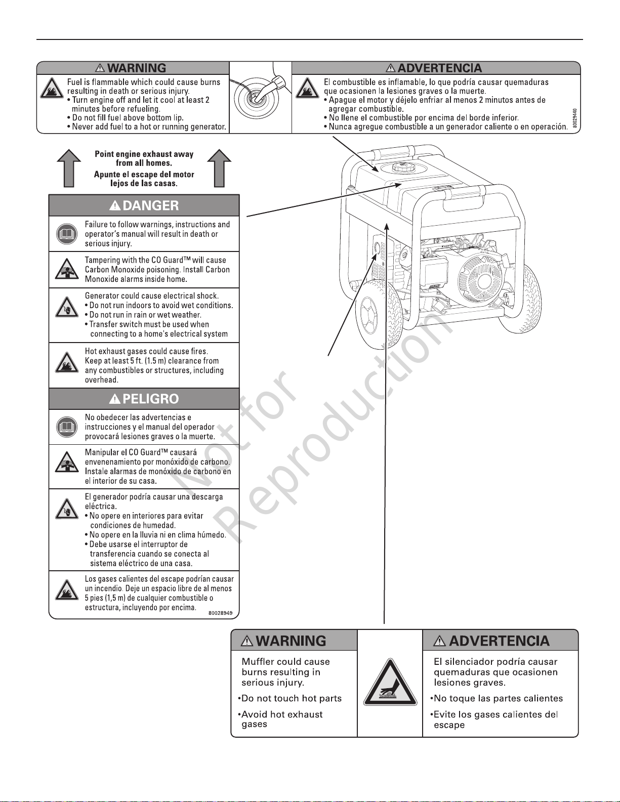
Exhaust/muffler
Point away from home
EN6 BRIGGSandSTRATTON.COM
Page 7
Not for
Reproduction
Operation
Operation
Step 1: Safe Location
Before starting the portable generator there are two equally
important safety concerns regarding carbon monoxide
poisoning and fire that must be addressed.
Operation Location to Reduce the Risk of
Carbon Monoxide Poisoning
The engine exhaust of all fossil fuel burning equipment,
such as a portable generator, contains carbon monoxide, a
poisonous gas that will kill you in minutes. You cannot smell
it, see it, or taste it. Even if you do not smell exhaust fumes,
you could still be exposed to carbon monoxide gas.
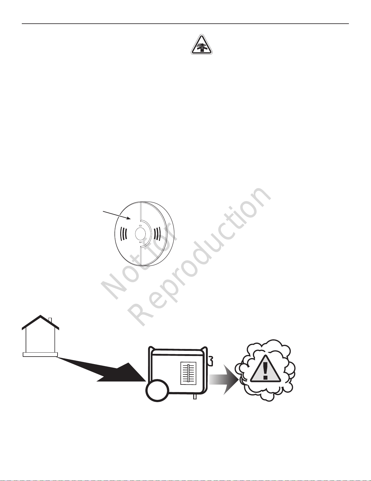
By law it is required in many states to have a carbon
monoxide alarm in operating condition in your home.
A carbon monoxide alarm is an electronic device that
detects hazardous levels of carbon monoxide. When there
is a buildup of carbon monoxide, the alarm will alert the
occupants by flashing visual indicator light and alarm.
Smoke alarms cannot detect carbon monoxide gas.
Carbon Monoxide Alarm(s)
Install carbon monoxide alarm
inside your home. Without
working carbon monoxide alarms,
you will not realize you are getting
sick and dying from carbon
monoxide poisoning.
DANGER! Engine exhaust contains carbon
monoxide, a poisonous gas that will kill you in
minutes. You cannot smell it, see it, or taste it.
Even if you do not smell exhaust fumes, you could still be
exposed to carbon monoxide gas.
• Operate portable generator only outdoors, at least
20 ft. (6.1 m) from occupied spaces with exhaust
pointed away to reduce the risk of carbon monoxide
accumulating.
• Install battery-operated carbon monoxide alarms or
plug-in carbon monoxide alarms with battery back-up
according to the manufacturer’s instructions. Smoke
alarms cannot detect carbon monoxide gas.
• Do not run portable generator inside homes, garages,
basements, crawlspaces, sheds, or other partiallyenclosed spaces even if using fans or opening doors
and windows for ventilation. Carbon monoxide can
quickly build up in these spaces and can linger for
hours, even after this product has shut off.
If you start to feel sick, dizzy, weak, or your homes carbon
monoxide alarm sounds while using this product, get to
fresh air right away. Call emergency services. You may have
carbon monoxide poisoning.
Prevent Carbon Monoxide (CO) Poisoning
• Use outdoors at least 20 ft. (6.1 m) from
any home.
• Point exhaust away from all homes and
occupied spaces.
• Install CO alarms inside your home.
20 ft. (6.1 m) min.
To better educate yourself about all carbon monoxide risks,
go to www.takeyourgeneratoroutside.com.
EN7
Page 8

Not for
Reproduction
Operation
Operation Location to Reduce the Risk of Fire
WARNING!
combustibles, structures or damage fuel tank
causing a fire, resulting in death or serious injury.
• Portable generator must be at least 5 ft. (1.5 m) from any
structure, overhang, trees, shrubs, or vegetation over 12
in. (30.5 cm) in height.
Exhaust heat/gases could ignite
• Do not place portable generator under a deck or other
type of structure that may confine airflow. Smoke alarm(s)
must be installed and maintained indoors according to the
manufacturer’s instructions/recommendations.
• Carbon monoxide alarms cannot detect smoke.
• Do not place portable generator in manner other than
shown.
5 ft. (1.5 m)
min.
5 ft. (1.5 m)
min.
MUFFLER
20 ft. (6.1 m) min.
EN8 BRIGGSandSTRATTON.COM
Page 9

Not for
Reproduction
Operation
Step 2: Oil and Fuel
The generator engine is shipped from the factory filled with
10W30 oil. This allows for generator operation in a wide
range of temperature and climate conditions. For checking/
adding or changing oil see Maintenance.
Fuel must meet these requirements:
•
Clean, fresh, unleaded fuel with a minimum of 87
octane.
• Gasoline with an ethanol content up to 10% is
acceptable.
E10
NOTICE Do not mix oil in fuel or modify engine to run on
alternate fuels. Use of unapproved fuels could damage
engine and will not be covered under warranty.
See High Altitude for 5,000 ft. and above.
• Do not refuel during operation.
• Do not smoke during refueling.
• Turn engine off and let it cool at least 2 minutes before
removing fuel cap.
• Fill fuel tank outdoors. Keep fuel away from sparks, open
flames, pilot lights, heat, and other ignition sources.
Check fuel lines, tank, cap and fittings frequently for
cracks or leaks. Replace if necessary.
1. Slowly remove fuel cap to relieve pressure in tank.
2. Slowly add unleaded fuel to fuel tank. Be careful not
E15
WARNING! Fuel and its vapors are extremely
flammable which could cause burns or fire
resulting in death or serious injury.
to fill above lip. This allows adequate space for fuel
expansion.
See an authorized Briggs & Stratton dealer for high altitude
adjustment information. Operation of the engine at altitudes
below 2,500 ft. (762 m) with the high altitude kit is not
recommended.
Transporting
When transporting equipment with a vehicle or trailer, turn
fuel shutoff valve to off (0) position. Do not tip engine or
equipment at an angle which causes fuel to spill.
Step 3: Generator Start Up
Disconnect all electrical loads from the generator. Use the
following start instructions:
1. Make sure unit is outdoors on a level surface.
NOTICE Failure to operate the unit on a level surface may
cause the unit to shut down.
2. Turn the fuel valve to the on (I) position.
Fuel Valve
3. Pull choke control out to close choke (
4. Turn and hold key in start switch to START position
until generator starts. DO NOT hold key in START
position for more than 5 seconds. Pause for at least
30 seconds between starting attempts.
).
3. Install fuel cap and let any spilled fuel evaporate
before starting engine.
High Altitude
At altitudes over 5,000 ft. (1524 m), a minimum 85 octane
fuel is acceptable. To remain emissions compliant, high
altitude adjustment is required. Operation without this
adjustment will cause decreased performance, increased
fuel consumption, and increased emissions.
Start Switch
NOTICE If battery is discharged, turn key in start switch
to RUN position, grasp recoil handle and pull slowly until
slight resistance is felt. Then pull rapidly one time only to
start engine.
5. Open choke gradually as engine warms up by pushing
in on choke handle.
NOTICE If engine starts but fails to run, see Low Oil
Shutdown in Features and Controls.
EN9
Page 10
Not for
Reproduction
Operation
Step 4: Connecting Electrical Loads
Using Extension Cords
Use only grounded extension cords marked for outdoor use
rated for your loads. Follow cord safety instructions.
WARNING! Damaged or overloaded extension
cords could overheat, arc, and burn resulting in
death or serious injury.
NOTICE For best results when plugging into the 120 Volt
receptacles, plug items to be powered in sequence as
shown.
1
3
NOTICE For generator output required see Generator
Capacity. Connect electrical loads in off position then turn
on for operation.
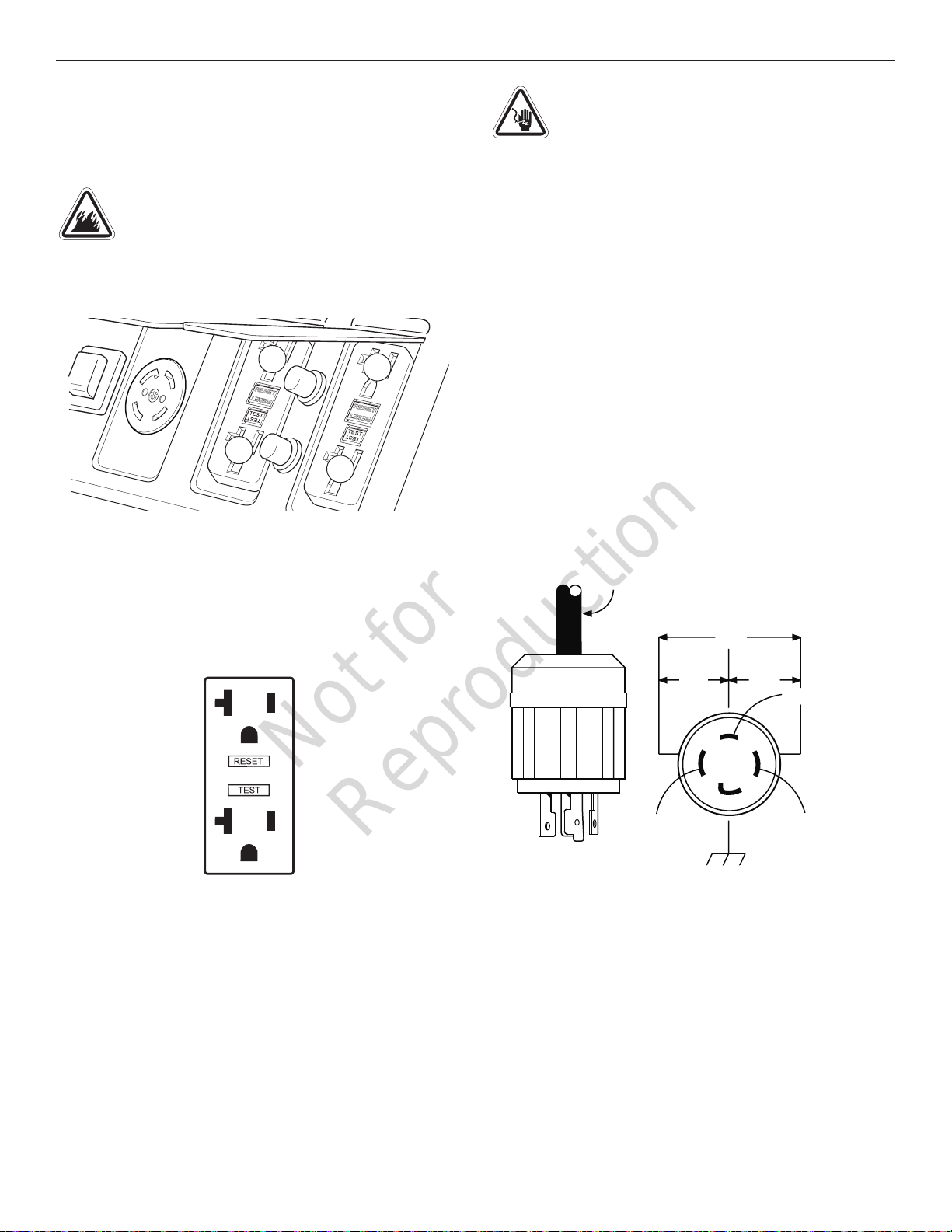
120 Volt AC, 20 Amp, GFCI Duplex Receptacles
Use each receptacle to operate 120 Volt AC, single-phase,
60 Hz electrical loads requiring up to 2,400 Watts (2.4 kW)
at 20 Amps of current.
2
4
WARNING! Generator voltage could cause
electrical shock or burn resulting in death or
serious injury. Contact with the hot and neutral
conductor at the same time could cause electrical shock
or burn, even if the circuit is GFCI protected.
Testing the GFCI
While generator is running, test each GFCI receptacle prior
to use, as follows:
• Push the “Test” button. The “Reset” button should
pop out, which should allow no power to reach the
receptacle.
• Press the “Reset” button firmly until it is fully in place
and locks in that position. If the GFCI receptacle does
not reset properly, do not use the receptacle. Call
or take your generator to a local Briggs & Stratton
authorized service dealer.
• If the GFCI trips by itself at any time, reset and test the
receptacle.
120/240 Volt AC, 30 Amp, Locking Receptacle
Use a NEMA L14-30 plug with this receptacle. Connect a
4-wire cord set rated for 250 Volt AC loads at 30 Amps. The
generator’s locking receptacle is not protected by a GFCI.
4-Wire Cord Set
240V
120V
120V
W (Neutral)
X (Hot)
Ground (Green)
Ground Fault Protection
The duplex receptacles are equipped with Ground Fault
Circuit Interrupter (GFCI) protection. The GFCI protects
against electrical shock that may be caused if your body
becomes a path which electricity travels to reach ground.
When protected by a GFCI, one may still feel a shock, but
the GFCI is intended to cut current off quickly enough so
that a person in normal health should not suffer any serious
electrical injury.
Y (Hot)
NEMA L14-30
This receptacle powers 120/240 Volt AC, 60 Hz, single
phase loads requiring up to 7,200 Watts of power (7.2kW)
at 30 Amps for 240 Volts or two independent 120 Volt loads
at 30 Amps each.
EN10 BRIGGSandSTRATTON.COM
Page 11

Not for
Reproduction
Operation
Generator Capacity
To make sure your generator can supply enough running
watts and starting watts for the items you will power at the
same time, follow these simple steps:
1. Select the items you will power at the same time. See
following list for typical wattages.
Tool or Appliance
Light Bulb - 75 Watt 75 Sump Pump - 1/3 HP 1140 2850
Refrigerator/Freezer 550 1350
Water Well Pump - 1/3 HP 575 1440
Window AC - 10,000 BTU 1000 2100
Furnace Fan Blower - 1/2 HP 800 2350
Microwave Oven - 1000 Watt 1000 Plasma Television - 50” 500 -
Laptop 250 Garage Door Opener - 1/2 HP 300 500
* Typical wattages listed are approximate only. Check tool
or appliance for actual wattage.
** Per Briggs & Stratton 628K, Starting Watts represents
the momentary electrical current the generator can
provide to start electric motors. Starting Watts does
not represent the power required to continuously run
electrical loads. Starting Watts is the maximum current
that can momentarily be supplied when starting a motor,
multiplied by the generator’s rated voltage.
2. Total the running watts. This is the amount of power
your generator must produce to keep your items
running. See following example:
Example
Tool or Appliance Running Watts Starting Watts
Window AC - 10000 BTU
Refrigerator/Freezer 550 1350
Plasma Television 500 —
Light (75 Watts) 75 —
Running Watts
Total running watts = 2125
Highest starting watts = 2100
Total generator watts required = 4225
3. Estimate the starting watts you will need. Because not
all motors start at the same time, total starting wattage
can be estimated by adding only the item with the
highest additional starting watts requirements to the
total running watts from step 2.
Running
Watts*
1000 2100
2125 Total
Starting
Watts**
2100 Highest
Starting Watts
Power Management
To manage generator power, sequentially add loads as
follows:
1. With nothing connected to generator, start the engine
outdoors.
2. Plug in and turn on the first load, preferably the largest
load you have.
3. Permit the generator output to stabilize (engine runs
smoothly and attached device operates properly).
4. Plug in and turn on the next load.
5. Again, permit the generator to stabilize.
6. Repeat steps 4 and 5 for each additional load.
Never add more loads than the generator capacity. Take
special care to consider surge loads in generator capacity.
CO Guard
Carbon Monoxide (CO) Shutdown System
CO Guard automatically shuts down the engine when
harmful levels of carbon monoxide accumulate around the
generator or a CO Guard fault occurs. After shutdown, the
CO Guard indicator light will blink for at least five minutes
per the chart below.
CO Guard DOES NOT replace carbon monoxide alarms.
Install battery-powered carbon monoxide alarm(s) in your
home. Don’t run generator in enclosed areas.
Color/Pattern Description
Red
•• ••
Blue
• • •
¥
Blue light will blink for five seconds at the startup of generator to
show CO Guard functioning properly.
Carbon monoxide accumulated around
generator. Move generator to an
open, outdoor area 20 ft. (6.1 m) from
occupied spaces with exhaust pointed
away. Automatic shutoff is an indication
generator was improperly located.
If you start to feel sick, dizzy, weak, or
your homes carbon monoxide alarm
sounds while using this product, get
to fresh air right away. Call emergency
services. You may have carbon
monoxide poisoning.
¥
CO Guard fault occured
See Briggs & Stratton authorized service
dealer.
.
Step 5: Generator Shutdown
1. Turn off and unplug all electrical loads from generator
panel receptacles. Never stop engine with electrical
devices plugged in and turned on.
2. Let engine run at no-load for one minute to stabilize
internal temperatures of engine and generator.
3. Turn key in start switch to 0FF position.
4. Move fuel valve to off (0) position.
EN11
Page 12

Not for
Reproduction
Maintenance
Maintenance
Maintenance Schedule
Follow the hourly or calendar intervals, whichever occurs
first. More frequent service is required when operating in
adverse conditions noted below.
First 5 Hours
• Change engine oil
Every 8 Hours or Daily
• Clean debris
• Check engine oil level
Every 25 Hours or Yearly
• Clean engine air filter
Every 100 Hours or Yearly
• Change engine oil
Yearly
• Replace engine air filter
• Service fuel valve
• Service spark plug
1
1
1
Cleaning
Daily or before use, look around and underneath
the generator for signs of oil or fuel leaks. Clean any
accumulated debris. Keep area around muffler free from
any debris.
• Use a soft bristle brush to loosen caked on dirt or oil.
• Use a damp cloth to wipe exterior surfaces clean.
NOTICE Improper treatment of generator could damage
it and shorten its life. Do not expose generator to excessive
moisture, dust, dirt, or corrosive vapors. Do not insert any
objects through cooling slots.
Fuel Valve Maintenance
The fuel valve is equipped with a fuel sediment cup,
screen, and o-ring that need to be cleaned.
1. Move fuel valve to off (0) position.
2. Remove sediment cup from fuel valve. Remove o-ring
and screen from fuel valve.
Screen
• Inspect muffler and spark arrester
1
Service more often under dirty or dusty conditions.
General Recommendations
Regular maintenance will improve the performance and
extend the life of the generator. See any authorized dealer
for service.
The generator’s warranty does not cover items that have
been subjected to operator abuse or negligence. To receive
full value from the warranty, the operator must maintain the
generator as instructed in this manual.
All service and adjustments should be made at least once
each season. A new spark plug and clean air filter assure
proper fuel-air mixture and help your engine run better and
last longer. Follow requirements in Maintenance Schedule.
Emissions Control
Maintenance, replacement, or repair of the emissions
control devices and systems may be performed by any
non-road engine repair establishment or individual.
However, to obtain ”no charge” emissions control service,
the work must be performed by a factory authorized dealer.
See Emissions Warranty.
O-Ring
Sediment Cup
3. Wash sediment cup, o-ring, and screen in a
nonflammable solvent. Dry them thoroughly.
4. Place screen and o-ring into fuel valve. Install
sediment cup and tighten securely.
5. Move fuel valve to on (I) position, and check for leaks.
Replace fuel valve if there is any leakage.
EN12 BRIGGSandSTRATTON.COM
Page 13

Not for
Reproduction
Maintenance
Engine Maintenance
Oil Recommendations
We recommend the use of Briggs & Stratton Warranty
Certified oils for best performance. Other high-quality
detergent oils are acceptable if classified for service SF or
higher. Do not use special additives. See Common Service
Parts.
Outdoor temperatures determine the proper oil viscosity for
the engine. Use the chart to select the best viscosity for the
outdoor temperature range expected.
* Below 4°C (40°F) the use of SAE 30 will result in hard starting.
** Above 27°C (80°F) the use of 10W30 may cause increased oil
consumption. Check oil level more frequently.
Checking/Adding Engine Oil
Oil level should be checked prior to each use or at least
every 8 hours of operation. Keep oil level maintained.
1. Make sure generator is on a level surface.
2. Clean area around oil fill, remove dipsitck and wipe
with clean cloth. Replace dipstick. Remove and check
oil level.
NOTICE Do not screw in dipstick when checking oil level.
3. Verify oil is at full mark on dipstick. Replace and
tighten dipstick.
Full
NOTICE Do not attempt to crank or start engine before
it has been properly serviced with recommended oil. This
could result in an engine failure.
CAUTION Avoid prolonged or repeated skin contact
with used motor oil. Used motor oil has been shown
to cause skin cancer in certain laboratory animals.
Thoroughly wash exposed areas with soap and water.
KEEP OUT OF REACH OF CHILDREN. DON’T
POLLUTE. CONSERVE RESOURCES. RETURN
USED OIL TO COLLECTION CENTERS.
Changing Engine Oil
If you are using your generator under extremely dirty or
dusty conditions, or in extremely hot weather, change the
oil more often.
Change the oil while the engine is still warm from running,
as follows:
1. Make sure unit is on a level surface.
2. Remove oil drain plug and drain oil completely into a
suitable container.
Oil Drain Plug
3. Reinstall oil drain plug and tighten securely. Remove
dipstick.
4. Slowly pour recommended oil (about 36 oz. (1.0 l)) into
oil fill opening. Pause to permit oil to settle. Fill to Full
mark on dipstick.
5. Wipe dipstick clean each time oil level is checked. Do
not overfill.
6. Reinstall dipstick. Tighten cap securely.
7. Wipe up any spilled oil.
4. If needed, slowly pour oil into oil fill opening to the full
mark on dipstick. Do not overfill.
NOTICE Overfilling with oil could cause the engine to not
start, or hard starting.
• Do not overfill.
• If over the full mark on dipstick, drain oil to reduce oil level to
full mark on dipstick.
5. Replace and tighten dipstick.
EN13
Page 14

Not for
Reproduction
Maintenance
Service Air Cleaner
WARNING! Fuel and its vapors are extremely
flammable which could cause burns or fire
resulting in death or serious injury.
• Do not start and run engine with air filter removed.
Your engine will not run properly and may be damaged if
you run it with a dirty air filter. Clean or replace more often if
operating under dusty or dirty conditions.
Your engine will not run properly and may be damaged if
you run it with a dirty air cleaner. Clean or replace more
often if operating under dusty or dirty conditions.
1. Loosen screws and remove air cleaner cover.
Base
Filter
Cover
Screws
Inspect Muffler and Spark Arrester
The engine exhaust muffler has a spark arrester screen.
Inspect the muffler for cracks, corrosion, or other damage.
Inspect spark arrester screen for damage or carbon
blockage. Clean if carbon blockage is found or replace if
damaged. If replacement parts are required, make sure to
use only original equipment replacement parts.
WARNING!
cause burns resulting in serious injury.
• Allow equipment to cool before servicing.
• It is a violation of California Public Resource Code,
Section 4442, to use or operate the engine on any forestcovered, brush-covered, or grass-covered land unless
the exhaust system is equipped with a spark arrester, as
defined in Section 4442, maintained in effective working
order. Other states or federal jurisdictions may have
similar laws, reference Federal Regulation 36 CFR Part
261.52.
Clean or replace spark arrester as follows:
1. Remove four screws that connect heat shield to
muffler.
Contact with muffler area could
Spark Arrester Screen
2. Carefully remove cartridge from base.
3. Install clean (or new) air cleaner assembly inside
cover. Dispose of old filter properly.
NOTICE If the filter is excessively dirty, replace with a new
filter. See Common Service Parts.
4. Assemble air cleaner cover onto base and tighten
screws.
Service Spark Plug
Changing the spark plug will help your engine to start
easier and run better.
1. Clean area around spark plug.
2. Remove and inspect spark plug.
3. Replace spark plug if electrodes are pitted, burned
or porcelain is cracked. Use the recommended
replacement spark plug. See Common Service Parts.
4. Check electrode gap with wire feeler gauge and reset
spark plug gap to recommended gap if necessary
(see Specifications).
Screws
Muffler
2. Remove four screws that attach spark arrester screen.
3. Obtain a replacement screen. See Common Service
Parts.
4. Reattach screen and muffler guard.
Common Service Parts
Air Cleaner ......................491588 or 5043
Spark Plug .............................491055
Engine Oil Bottle ...............100005 or 100028
Synthetic Oil Bottle ......................100074
Contact an authorized service dealer or
BRIGGSandSTRATTON.COM for a full list of parts and
diagrams.
Heatshield
Screws
5. Install spark plug and tighten firmly.
EN14 BRIGGSandSTRATTON.COM
Page 15

Not for
Reproduction
Storage
Storage
If storing the unit for more than 30 days, use the following
guidelines to prepare it for storage.
Long Term Storage Instructions
1. Clean the generator as outlined in Cleaning.
2. Change engine oil while engine is still warm, drain oil
from crankcase. Refill with recommended grade. See
Changing Engine Oil.
3. Treat or drain fuel from generator as fuel can become
stale when stored over 30 days.
Stale fuel causes acid and gum deposits to form in the fuel
system or on essential carburetor parts. To keep fuel fresh,
use a fuel stabilizer.
There is no need to drain gasoline from the engine if a
fuel stabilizer is added according to instructions. Run the
engine for 2 minutes to circulate the stabilizer throughout
the fuel system before storage.
If gasoline in the engine has not been treated with a fuel
stabilizer, it must be drained into an approved container.
Run the engine until it stops from lack of fuel. The use of a
fuel stabilizer in the storage container is recommended to
maintain freshness.
WARNING!
flammable and explosive which could cause
burns, fire or explosion resulting in death or
serious injury.
• When storing fuel or equipment with fuel in tank, store
away from furnaces, stoves, water heaters, clothes dryers
or other appliances that have pilot light or other ignition
source because they could ignite fuel vapors.
• When draining fuel, turn generator engine off and let it
cool at least 2 minutes before removing fuel cap. Loosen
cap slowly to relieve pressure in tank. Drain fuel tank
outdoors. Keep fuel away from sparks, open flames, pilot
lights, heat, and other ignition sources.
• Check fuel lines, tank, cap and fittings frequently for
cracks or leaks. Replace if necessary.
Fuel and its vapors are extremely
4. Store generator in clean, dry area and cover with a
suitable protective cover that does not retain moisture.
WARNING! Storage covers could cause a fire
resulting in death or serious injury.
• Do not place a storage cover over a hot generator. Let
equipment cool for a sufficient time before placing the
cover on the equipment.
FCC Compliance Statement
FCC Part 15 Information to User
Pursuant to part 15.21 of the FCC Rules, you are cautioned
that changes or modifications to transceiver not expressly
approved by Briggs & Stratton could void your authority to
operate the portable generator.
This device complies with part 15 of the FCC Rules.
Operation is subject to the following two conditions: (1) This
device may not cause harmful interference, and (2) this
device must accept any interference received, including
interference that may cause undesired operation.
This equipment has been tested and found to comply with
the limits for a Class B digital device, pursuant to part 15
of the FCC Rules. These limits are designed to provide
reasonable protection against harmful interference in a
residential installation. This equipment generates, uses
and can radiate radio frequency energy and, if not installed
and used in accordance with the instructions, may cause
harmful interference to radio communications. However,
there is no guarantee that interference will not occur in a
particular installation. If this equipment does cause harmful
interference to radio or television reception, which can be
determined by turning the equipment off and on, the user
is encouraged to try to correct the interference by one or
more of the following measures:
• Reorient or relocate the receiving antenna.
• Increase the separation between the equipment and
receiver.
• Connect the equipment into an outlet on a circuit
different from that to which the receiver is connected.
• Consult the dealer or an experienced radio/TV
technician for help.
EN15
Page 16

Not for
Reproduction
Troubleshooting/Specifications
Problem Cause Correction
Engine is running, but no AC
output is available.
Engine runs well at no-load but
“bogs down” when loads are
connected.
Engine will not start; starts and
runs rough or shuts down when
running.
Engine shuts down and CO
Guard LED blinks red (•• ••).
1. One of the circuit breakers is open.
2. Poor connection or defective cord set.
3. Connected device is bad.
4. GFCI tripped.
1. Generator is overloaded. 1. See Generator Capacity.
1. Engine switch set to OFF position.
2. Fuel valve is in off (0) position.
3. Low oil level.
4. Dirty air cleaner.
5. Out of fuel.
6. Spark plug wire not connected to
spark plug.
7. Flooded with fuel.
1. Generator improperly located.
1. Reset circuit breaker.
2. Check and repair.
3. Connect another device that is in
good condition.
4. Reset GFCI.
1. Set switch to RUN position.
2. Turn fuel valve to on (I) position.
3. Fill crankcase to proper level or
place generator on level surface.
4. Clean or replace air cleaner.
5. Fill fuel tank.
6. Connect wire to spark plug.
7. Wait 5 minutes and re-crank engine.
1. Move generator to an open, outdoor
area. See CO Guard Carbon
Monoxide (CO) Shutdown System.
For all other issues, see a Briggs & Stratton authorized dealer.
Specifications
Model 030740
Running Watts* ...........................7,000
Starting Watts** ...........................8,750
AC Current at 240 Volts ................ 29.1 Amps
AC Current at 120 Volts ................ 58.3 Amps
Model 030741
Rated Wattage* ...........................8,000
Starting Wattage** ........................10,000
AC Current at 240 Volts ................ 33.3 Amps
AC Current at 120 Volts ................ 66.6 Amps
Power Ratings: The gross power rating for individual gasoline engine models is labeled in accordance with SAE (Society of Automotive
Engineers) code J1940 Small Engine Power & Torque Rating Procedure, and is rated in accordance with SAE J1995. Torque values are
derived at 2600 RPM for those engines with “rpm” called out on the label and 3060 RPM for all others; horsepower values are derived
at 3600 RPM. The gross power curves can be viewed at www.BRIGGSandSTRATTON.COM. Net power values are taken with exhaust
and air cleaner installed whereas gross power values are collected without these attachments. Actual gross engine power will be higher
than net engine power and is affected by, among other things, ambient operating conditions and engine-to-engine variability. Given the
wide array of products on which engines are placed, the gasoline engine may not develop the rated gross power when used in a given
piece of power equipment. This difference is due to a variety of factors including, but not limited to, the variety of engine components
(air cleaner, exhaust, charging, cooling, carburetor, fuel pump, etc.), application limitations, ambient operating conditions (temperature,
humidity, altitude), and engine-to engine variability. Due to manufacturing and capacity limitations, Briggs & Stratton may substitute an
engine of higher rated power for this engine.
* Generator per PGMA (Portable Generator Manufacturers’ Association) standard ANSI/PGMA G300-2018, Safety and Performance of
Portable Generators.
** Per Briggs & Stratton 628K
Common Specifications
Frequency .....................60 Hz at 3600 rpm
Phase ............................Single Phase
Displacement ................25.63 cu. in. (420 cc)
Spark Plug Gap ...............0.030 in. (0.76 mm)
Fuel Capacity .........7.5 U.S. Gallons (28.4 Liters)
Oil Capacity ................36 Ounces (1.0 Liters)
EN16 BRIGGSandSTRATTON.COM
Page 17

Not for
Reproduction
Notes
EN17
Page 18

Not for
Reproduction
Warranty
BRIGGS & STRATTON PRODUCTS WARRANTY POLICY
LIMITED WARRANTY
Briggs & Stratton warrants that, during the warranty period specified below, it will repair or replace, free of charge, any part that is defective in material or workmanship
or both. Transportation charges on product submitted for repair or replacement under this warranty must be borne by purchaser. This warranty is effective for
and is subject to the time periods and conditions stated below. For warranty service, find the nearest Authorized Service Dealer in our dealer locator map at
BRIGGSandSTATTON.COM. The purchaser must contact the Authorized Service Dealer, and then make the product available to the Authorized Service Dealer for
inspection and testing.
There is no other express warranty. Implied warranties, including those of merchantability and fitness for a particular purpose, are limited to the
warranty period listed below, or to the extent permitted by law. Liability for incidental or consequential damages are excluded to the extent exclusion is
permitted by law. Some states or countries do not allow limitations on how long an implied warranty lasts, and some states or countries do not allow the exclusion or
limitation of incidental or consequential damages, so the above limitation and exclusion may not apply to you. This warranty gives you specific legal rights and you may
also have other rights which vary from state to state or country to country.**
WARRANTY PERIOD
Item Consumer Use Commercial Use
Equipment 36 months ▲ 12 months
Engine* 24 months 12 months
Battery (if equipped) 3 months None
▲ After 12 months, warranty covers parts only.
* Applies to Briggs & Stratton engines only. Warranty coverage of non-Briggs & Stratton engines is provided by that engine manufacturer. Emissions-related components
are covered by the Emissions Warranty Statement.
** In Australia - Our goods come with guarantees that cannot be excluded under the Australian Consumer Law. You are entitled to a replacement or refund for a major
failure and for compensation for any other reasonably foreseeable loss or damage. You are also entitled to have the goods repaired or replaced if the goods fail to be
of acceptable quality and the failure does not amount to a major failure. For warranty service, find the nearest Authorized Service Dealer in our dealer locator map at
BRIGGSandSTRATTON.COM, or by calling 1300 274 447, or by emailing or writing to salesenquires@briggsandstratton.com.au, Briggs & Stratton Australia Pty Ltd, 1
Moorebank Avenue, NSW, Australia, 2170.
The warranty period begins on the date of purchase by the first retail or commercial consumer. “Consumer use” means personal residential household use by a retail
consumer. “Commercial use” means all other uses, including use for commercial, income producing or rental purposes. Once a product has experienced commercial use,
it shall thereafter be considered as a commercial use product for purposes of this warranty.
Save your proof of purchase receipt. If you do not provide proof of the initial purchase date at the time warranty service is requested, the manufacturing date of the
product will be used to determine the warranty period. Product registration is not required to obtain warranty service on Briggs & Stratton products.
ABOUT YOUR WARRANTY
Warranty service is available only through Briggs & Stratton Authorized Service Dealers. This warranty covers only defects in materials or workmanship. It does not cover
damage caused by improper use or abuse, improper maintenance or repair, normal wear and tear, or stale or unapproved fuel.
Improper Use and Abuse - The proper, intended use of this product is described in the Operator’s Manual. Using the product in a way not described in the Operator’s
Manual or using the product after it has been damaged will not be covered under this warranty. Warranty coverage will also not be provided if the serial number on the
product has been removed or the product has been altered or modified in any way, or if the product has evidence of abuse such as impact damage or water/chemical
corrosion damage.
Improper Maintenance or Repair - This product must be maintained according to the procedures and schedules provided in the Operator’s Manual, and serviced or
repaired using genuine Briggs & Stratton parts or equivalent. Damage caused by lack of maintenance or use of non-original parts is not covered by warranty.
Normal Wear and Tear - Like most mechanical devices, your unit is subject to wear even when properly maintained. This warranty does not cover repairs when normal
use has exhausted the life of a part or the equipment. Maintenance and wear items such as filters, belts, cutting blades, and brake pads (except engine brake pads) are
not covered by warranty due to wear characteristics alone, unless the cause is due to defects in material or workmanship.
Stale or Unapproved Fuel - In order to function correctly, this product requires fresh fuel that conforms to the criteria specified in the Operator’s Manual. Engine or
equipment damage caused by stale fuel or the use of unapproved fuels (such as E15 or E85 ethanol blends) is not covered by warranty.
Other Exclusions - This warranty excludes damage due to accident, abuse, modifications, alterations, improper servicing, freezing or chemical deterioration.
Attachments or accessories that were not originally packaged with the product are also excluded. There is no warranty coverage on equipment used for primary power in
place of utility power or on equipment used in life support applications. This warranty does not include used, reconditioned, second-hand, or demonstration equipment or
engines. This warranty also excludes failures due to acts of God and other force majeure events beyond the manufacturer’s control.
80011056_EN Rev A
EN18 BRIGGSandSTRATTON.COM
Page 19

Not for
Reproduction
Generador portátil para
uso en exteriores
Manual del operador
Número de modelo __________________________
Revisión __________________________________
Número de serie ____________________________
Fecha de compra ___________________________
Copyright © 2018. Briggs & Stratton Corporation
Milwaukee, WI, USA. Todos los derechos reservados.
800-743-4115
BRIGGSandSTRATTON.COM
Page 20

Not for
Reproduction
Descripción del equipo
Índice
Descripción del equipo.........................2
Características y controles......................5
Operación ...................................7
Mantenimiento ..............................13
Almacenamiento.............................16
Declaración de cumplimiento de la FCC .........16
Solución de problemas/Especificaciones.........17
Garantía....................................18
Registre su producto
Con el fin de garantizar la cobertura de la garantía de
forma oportuna y completa, registre su producto en línea
en www.onlineproductregistration.com.
Símbolos y advertencias
Señal Advertencias
PELIGRO
ADVERTENCIA
PRECAUCIÓN
AVISO
Símbolo Nombre Explicación
Símbolo de
alerta de
seguridad
Manual del
operador
Gases
Tóxicos
Incendio
Indica un peligro que, si no se evita,
ocasionará la muerte o lesiones graves.
Indica un peligro que si no es evitado,
podría ocasionar la muerte o heridas
graves.
Indica un peligro que, si no se evita,
podría ocasionar lesiones menores o
moderadas.
Indica una información considerada
importante, pero no relacionada con un
peligro.
Indica un posible riesgo para su
integridad física.
El no cumplir con leer y seguir las
advertencias, las instrucciones y
el manual del operador podrían
dar como resultado la muerte o
lesiones graves.
La descarga de escape del motor
contiene monóxido de carbono, un
gas tóxico que mata en cuestión
de minutos. No puede olerse ni
verse.
El combustible y sus vapores son
extremadamente inflamables, lo
que podría causar quemaduras
o incendios que conlleven la
muerte o lesiones graves.
El escape del motor puede
causar un incendio que conlleve
la muerte o lesiones graves.
Símbolo Nombre Explicación
Descarga
eléctrica
Superficie
caliente
¡ADVERTENCIA! Este producto puede
exponerlo a sustancias químicas, entre las que
se incluyen emisiones de escape de motor de
gasolina, reconocidas por el Estado de California como
causantes de cáncer, y monóxido de carbono, reconocido
por el Estado de California como causante de defectos de
nacimiento u otros problemas reproductivos. Para obtener
más información, visite www.P65Warnings.ca.gov
El generador podría provocar
electrocución que conlleve
lesiones graves o la muerte.
El silenciador puede causar
quemaduras que podrían
comportar lesiones graves.
Descripción del equipo
Lea este manual cuidadosamente y familiarícese
con el generador. Conozca sus aplicaciones, sus
limitaciones, y cualquier riesgo implicado. Guarde
estas instrucciones para futuras consultas.
El generador para exteriores es un generador de corriente
alterna (CA), accionado por motor, de campo giratorio
equipado con un regulador de voltaje. Este generador
está diseñado para suministrar energía eléctrica para
iluminación, aparatos, herramientas y motores compatibles.
El regulador de voltaje dentro del generador está diseñado
para mantener el nivel de voltaje de salida automáticamente.
Puede utilizar el generador eléctrico portátil para alimentar
aparatos al aire libre usando cables de extensión o
para restaurar la energía eléctrica del hogar usando un
interruptor de transferencia. Una llave de transferencia es
un dispositivo independiente que instala un electricista con
licencia para conectar el generador portátil con cables,
mediante una toma de bloqueo, directamente al sistema
eléctrico de su hogar. Instale una llave de transferencia de
la lista lo antes posible si el generador se usará para el
restablecimiento temporal de la energía eléctrica del hogar.
Se ha realizado el máximo esfuerzo para reunir en este
manual la información más precisa y actualizada. No
obstante, el fabricante se reserva el derecho de modificar,
alterar o mejorar de cualquier otra forma el generador y
este documento en cualquier momento y sin previo aviso.
AVISO Si tiene alguna pregunta acerca del uso esperado,
póngase en contacto con el distribuidor autorizado. Este
equipo se ha diseñado para usarse con partes autorizadas
de Briggs & Stratton® únicamente.
ES2 BRIGGSandSTRATTON.COM
Page 21

Not for
Reproduction
Descripción del equipo
Puesta a tierra del sistema
El sistema tiene una puesta a tierra del sistema que conecta
los componentes de la estructura del generador con los
terminales de tierra en las tomas de salida de CA. La puesta
a tierra del sistema está conectada al cable neutral CA (el
cable neutral está unido a la estructura del generador).
Requisitos especiales
Pueden existir ordenanzas o códigos locales, federales o
del estado que se apliquen al uso previsto del generador.
Consulte a un electricista calificado, a un inspector
eléctrico o a la agencia local con jurisdicción en el tema:
Este generador no debe utilizarse en un emplazamiento de
obra según se define por NFPA 70-2017 (NEC) sección 590.6.
Proporcionar energía usando cables
prolongadores
Toma de
120V
120V
OUTLET
5. NO SE RECOMIENDAN los cables de extensión que
se conectan directamente a la casa para alimentar
dispositivos para interiores.
¡PELIGRO! La descarga de escape del motor
contiene monóxido de carbono, un gas tóxico que
mata en cuestión de minutos. Además de que no
se lo puede ver, es inodoro e insípido. Incluso si no huele
los gases del escape, puede estar expuesto al monóxido
de carbono.
• Los cables de extensión que se conectan
directamente a la casa aumentan el riesgo de
intoxicación por monóxido de carbono a través de
orificios.
• Si se usa el cable de extensión que se conecta
directamente a la casa para alimentar dispositivos
para interiores, el operador reconoce que esto
aumenta el riesgo de intoxicación por monóxido de
carbono de las personas que se encuentren dentro de
la casa y, por consiguiente, asume tal riesgo.
6. Instale una interruptores de transferencia de la lista*
lo antes posible si el generador se usará para el
restablecimiento de la energía eléctrica del hogar.
1. Solo use cables de extensión con conexión a tierra
identificados para el uso en exteriores y con la
clasificación adecuada para sus cargas.
Proporcionar energía usando
Amperaje
total
Hasta 13A
Hasta 15A
Hasta 20A
Hasta 30A
cables prolongadores
Válvula mínima con clasificación para
exteriores
Hasta 15m (50 pies) Hasta 30m (100 pies)
16
14
12
10
14
12
10
8
Restablecer la energía de su hogar con uno
de los interruptores de transferencia de la
lista
Las conexiones al sistema eléctrico de su hogar deben
usar un interruptor de transferencia de la lista* y un
electricista con licencia debe instalarlo. La conexión
debe aislar al generador de energía del suministro de
electricidad y cumplir con todas las leyes correspondientes
y códigos eléctricos. Suministre energía a su hogar con un
sistema de interruptor de transferencia de 30 A.
Toma de
120/240V
Aparatos comunes dentro casa
—
Interruptor de
transferencia
2. Siga las instrucciones de seguridad de los cables.
3. Instale alarmas de monóxido de carbono.
4. Cuando use el generador con cables de extensión,
asegúrese de colocarlo en un área abierta, exterior,
a una distancia de al menos 6.1 m (20 pies) de
espacios donde haya personas u objetos y con el
escape apuntando en la dirección opuesta.
* Certificado por un laboratorio de pruebas reconocido a nivel
nacional que indique que el producto cumple con los estándares
adecuados de prueba de seguridad de productos.
ES3ES3
Page 22

Not for
Reproduction
Descripción del equipo
Control del cebador
Identificación del motor
Tapa de llenado del aceite/varilla medidora
Tapón para el vaciado de aceite
Sujetador de tierra
Tapa del combustible
Válvula de combustible
Silenciador con extintor de chispas/Escape
Arrancador retráctil
Filtro de aire
Etiqueta de identificación
Arrancador retráctil — Permite arrancar manualmente el
motor.
Control del cebador — Se usa cuando se arranca el motor
en frío.
Etiqueta de identificación — Proporciona el modelo y el
número de serie del generador.
Filtro de aire — Filtra el aire que entra al motor.
Identificación del motor — Proporciona modelo, tipo y
código del motor.
Silenciador con supresor de chispas /Escape — El
silenciador reduce el ruido del motor y está equipado con
una pantalla que detiene las chispas.
Sujetador de tierra — Consulte con la agencia local con
jurisdicción en el tema sobre los requisitos de conexión a
tierra en su área.
Tapa de combustible — Añada combustible sin plomo aquí.
Tapa de llenado del aceite/varilla medidora — Compruebe
y añada el aceite del motor aquí.
Tapón para el vaciado de aceite — Vacíe el aceite del
motor aquí.
Válvula de combustible — Se usa para encender o apagar
el suministro de combustible.
ES4 BRIGGSandSTRATTON.COM
Page 23

Not for
Reproduction
Características y controles
Compare las ilustraciones con su generador para familiarizarse con la ubicación de los diversos controles y advertencias
del producto.
Receptáculo de
Luz indicadora del
sistema de apagado
por monóxido de
carbono (CO) CO
Guard™
bloqueo de 120 o 240
voltios de AC, 30 A
202997
Interruptor
de arranque
Contador
de la hora
Interruptor basculante
de cortacircuitos
Apagado por bajo
nivel de aceite
Apagado por bajo nivel de aceite — Esta unidad está
equipada con un dispositivo de protección contra bajo
nivel de aceite. Para que el motor arranque y funcione, el
nivel del aceite debe ser adecuado. Si la presión de aceite
del motor cae por debajo del nivel predeterminado, el
interruptor de nivel de aceite detiene el motor. Compruebe
el nivel de aceite con la varilla medidora.
Contador de la hora — Muestra y registra las horas que ha
funcionado su generador (hasta 9,999.9).
Interruptores (AC) — Los receptáculos dobles GFCI de
120 voltios de 20 A cuentan con interruptores con un botón
de «restablecimiento» de 20 A para proteger al generador
de una sobrecarga eléctrica.
Interruptor basculante de cortacircuitos — El receptáculo de
bloqueo de 30 A cuenta con un interruptor basculante de 2
polos para proteger al generador de una sobrecarga eléctrica.
Interruptores
de circuito
Receptáculo doble GFCI
de 120 voltios de AC, 20 A
Interruptor de arranque — Gire la llave a la posición
START (arranque) para encender el motor. Gire la llave a la
posición OFF para apagar el motor.
Luz indicadora del sistema de apagado por monóxido
de carbono (CO) CO Guard™ — Indica el apagado del
motor debido a una acumulación de monóxido de carbono
alrededor del generador o a una falla ocurrida en el
sistema CO Guard.
Receptáculo doble GFCI de 120 voltios de AC, 20 A —
Se usa para suministrar energía de 120 voltios de AC,
monofásica y de 60 Hz para operar luces, electrodomésticos,
herramientas y cargas de motores eléctricos.
Receptáculo de bloqueo de 120/240 voltios de AC, 30 A —
Se usa para suministrar energía de 120/240 voltios de AC,
monofásica y de 60 Hz para operar luces, electrodomésticos,
herramientas y cargas de motores eléctricos.
ES5ES5
Page 24

Not for
Reproduction
Características y controles
Mofle/Escape
Apúntelo lejos de la casa.
ES6 BRIGGSandSTRATTON.COM
Page 25

Not for
Reproduction
Operación
Operación
Paso 1: Ubicación segura
Antes de arrancar el generador portátil hay dos problemas
de seguridad igualmente importantes con respecto a la
intoxicación por monóxido de carbono e incendios que
debe abordarse.
Ubicación de funcionamiento del generador portátil
para reducir el riesgo de intoxicación por monóxido
de carbono
El escape del motor de todos los equipos que queman
combustibles fósiles, como el generador portátil, contiene
monóxido de carbono, un gas tóxico que mata en cuestión
de minutos. Además de que no se lo puede ver, es inodoro
e insípido. Incluso si no huele los gases del escape, puede
estar expuesto al monóxido de carbono.
En muchos estados, la ley requiere el uso de alarmas
de monóxido de carbono en las casas. Se trata de un
dispositivo electrónico que detecta niveles peligrosos
de monóxido de carbono. Cuando se produce una
acumulación de monóxido de carbono, la alarma avisa a
los habitantes con un sonido y una luz indicadora, visible e
intermitente. Las alarmas de humo no pueden detectar el
monóxido de carbono.
Alarma(s) de monóxido de
carbono
Instale alarmas de monóxido
de carbono dentro de su casa.
Sin alarmas de monóxido de
carbono en funcionamiento, no
se dará cuenta de que se está
intoxicando y muriendo debido a
una intoxicación por monóxido de
carbono.
Evite la intoxicación por monóxido de
carbono (CO)
• Utilice en exteriores al menos 6.1 m (20 pies)
de cualquier casa.
• Apunte el escape en la dirección opuesta
de las casas y de los espacios donde haya
personas u objetos.
• Instale alarmas de CO dentro de su casa.
¡PELIGRO! El escape del motor contiene
monóxido de carbono, un gas tóxico que puede
matar en minutos. NO puede olerlo, verlo ni
saborearlo. Incluso si no huele los gases del escape,
puede estar expuesto al monóxido de carbono.
• Opere generador portátil únicamente en exteriores y a
una distancia de al menos 6.1 m (20 pies) de espacios
donde haya personas u objetos, con el escape
apuntando en la dirección opuesta para reducir el
riesgo de acumulación de monóxido de carbono.
• Instale alarmas de monóxido de carbono con baterías
o enchufe (batería de respaldo) siguiendo las
instrucciones del fabricante. Las alarmas de humo no
pueden detectar el monóxido de carbono.
• No opere generador portátil dentro de hogares,
garajes, sótanos, espacios reducidos, cobertizos u
otros espacios parcialmente cerrados, incluso si usa
ventiladores o deja las puertas y ventanas abiertas. El
monóxido de carbono se puede acumular rápidamente
en estos espacios y puede permanecer durante horas,
incluso después de que se apaga este producto.
Si comienza a sentirse mal, mareado o débil o si la
alarma de monóxido de carbono de su hogar empieza
a sonar mientras utiliza el producto, tome aire fresco
inmediatamente. Llame a los servicios de emergencia.
Puede haberse intoxicado con monóxido de carbono.
6.1 m (20 pies) min.
Para obtener más información sobre los riesgos del monóxido
de carbono, visite www.takeyourgeneratoroutside.com.
ES7ES7
Page 26

Not for
Reproduction
Operación
Ubicación de funcionamiento para reducir el riesgo
de incendio
¡ADVERTENCIA! Los gases y el calor de escape
pueden inflamar los materiales combustibles y las
estructuras o dañar el tanque de combustible y
provocar un incendio, lo que podría comportar la muerte o
lesiones graves.
• El generador portátil debe encontrarse al menos a
1.5 m (5 pies) de cualquier estructura, alero, arbustos,
árboles, o vegetación de más de 30.5 cm (12 in) de
altura.
• No coloque el generador portátil bajo una cubierta
u otro tipo de estructura que pueda limitar el flujo de
aire. Se deben instalar y mantener alarma(s) de humo
en el interior de acuerdo con las instrucciones y/o
recomendaciones del fabricante.
• Las alarmas de monóxido de carbono no pueden
detectar el humo.
• No coloque el generador portátil en forma distinta a la
que se muestra.
1.5 m (5 pies)
min.
Mofle
MUFFLER
1.5 m (5 pies)
min.
6.1 m (20 pies) min.
ES8 BRIGGSandSTRATTON.COM
Page 27

Not for
Reproduction
Operación
Paso 2: Aceite y combustible
El motor del generador se envía de fábrica lleno de aceite
10W30. De esta manera, el generador funcionará con un
amplio rango de temperatura y de condiciones climáticas.
Para revisar, agregar o cambiar el aceite consulte la
sección Mantenimiento.
El combustible debe cumplir con estos requisitos:
• Ser un combustible sin plomo, fresco, limpio y con un
mínimo de 87 octanos.
• Se acepta gasolina que contenga hasta 10 % de etanol.
E10
AVISO No mezcle el aceite con el combustible ni
modifique el motor para que opere con combustibles
alternos. El uso de combustibles sin aprobación puede
dañar el motor y no está cubierto por la garantía.
Consulte la sección Gran altura en el caso de estar a una
altura de 1524 m (5000 pies) o superior.
muerte o lesiones graves.
• No recargue combustible si el generador está en
funcionamiento.
• No fume durante la carga de combustible.
• Apague el motor y déjelo enfriar por al menos 2 minutos
antes de retirar la tapa de combustible.
• Llene el tanque de combustible al aire libre. Mantenga el
combustible alejado de chispas, llamas abiertas, llamas
pilotos, fuentes de calor y otras fuentes de ignición.
Compruebe con frecuencia si existen grietas o fugas en
las mangueras de combustible, el tanque, la tapa y los
accesorios. Cambie si es necesario.
1. Quite lentamente la tapa para eliminar la presión del
2. Agregue lentamente combustible sin plomo en el
E15
¡ADVERTENCIA! El combustible y sus vapores
son extremadamente inflamables, lo que podría
causar quemaduras o incendios que conlleven la
tanque.
tanque de combustible. Tenga cuidado de no añadir
combustible por encima de la solapa. Esto permite
que quede el espacio adecuado para permitir la
expansión del combustible.
3. Instale la tapa del tanque de combustible y espere
a que se evapore el combustible que se haya
derramado antes de arrancar el motor.
Gran altitud
A altitudes superiores a los 1524 m (5000 pies), es
aceptable usar gasolina con un mínimo de 85 octanos.
Para permanecer en cumplimiento con el control de
emisiones, se requiere el ajuste de alta altitud. El
funcionamiento sin este ajuste provocará una disminución
en el rendimiento y un aumento en el consumo de
combustible y en las emisiones.
Consulte a su distribuidor autorizado de Briggs & Stratton
para obtener información sobre el ajuste para gran altitud.
No se recomienda operar el motor a altitudes inferiores a
762 m (2500 pies) con el kit para gran altitud.
Transporte
Al transportar equipo con un vehículo o remolque, gire la
válvula de cierre de combustible a la posición apagada (0).
No incline el motor ni el equipo en un ángulo que provoque
un derrame de combustible.
Paso 3: Puesta en marcha del generador
Desconecte todas las cargas eléctricas del generador.
Siga las siguientes instrucciones de puesta en marcha:
1. Asegúrese de que la unidad esté al aire libre sobre
una superficie nivelada.
AVISO No operar la unidad en una superficie plana
puede hacer que la unidad se apague.
2. Coloque la válvula de combustible en la posición de
encendido ON (I).
Válvula de
combustible
3. Active el control del cebador hasta cebarlo ( ).
ES9ES9
Page 28

Not for
Reproduction
Operación
4. Gire y sostenga la llave en la posición ARRANQUE
hasta que arranque el generador. NO mantenga
la llave en la posición ARRANQUE por más de 5
segundos. Haga una pausa de por lo menos 30
segundos entre intentos de arrancar.
Interruptor
de arranque
AVISO Si la batería está descargada, gire la llave en el
interruptor de arranque a la posición CORRER, tome la
manija retráctil y hálela lentamente hasta que sienta una
ligera resistencia. Luego hale rápidamente una sola vez
para arrancar el motor.
5. Ponga en marcha el cebador progresivamente a
medida que el motor se calienta y empuja la manija
del cebador.
AVISO Si el motor arranca pero no funciona, consulte
la sección de apagado por bajo nivel de aceite en
Características y controles.
Paso 4: Cómo conectar las cargas eléctricas
Uso de los cables prolongadores
Solo use cables prolongadores identificados para el uso en
exteriores y con la clasificación adecuada para sus cargas.
Siga las instrucciones de seguridad de los cables.
¡ADVERTENCIA! Cables prolongadores
dañados o sobrecargados pueden recalentarse,
formar arco y quemarse dando lugar a riesgos
de muerte o lesiones graves.
AVISO Para obtener mejores resultados al conectar
aparatos en las tomas de 120 voltios, conéctelos de esta
forma para que consuman energía de forma secuencial.
1
3
AVISO Para verificar la salida del generador requerida
consulte la sección Capacidad del generador. Conecte
las cargas eléctricas en la posición de apagado (OFF) y
proceda a encender.
2
4
Toma doble GFCI de 120 voltios de CA, 20 A
Use cada toma para operar cargas eléctricas monofásicas
de 120 voltios de CA y 60 Hz que requieran hasta 2400
vatios (2.4 kW) con una corriente de 20 A.
Protección contra fallos de la conexión a tierra
Las tomas dobles cuentan con un interruptor de circuito de
tierra accidental (Ground Fault Circuit Interrupter, GFCI) para
su protección. El GFCI brinda protección contra descargas
eléctricas que pueden ocurrir si su cuerpo forma un camino
por el que la electricidad puede llegar a tierra.
Es posible sentir una descarga aunque haya un GFCI;
sin embargo, el GFCI está diseñado para interrumpir la
corriente rápidamente y que una persona no sufra ninguna
lesión eléctrica grave.
¡ADVERTENCIA! La tensión del generador
podría provocar electrocución o quemaduras que
conlleven lesiones graves o la muerte. Entrar en
contacto con el conductor neutro y el conductor con
voltaje al mismo tiempo podría provocar una descargar
eléctrica o quemaduras, incluso si el circuito cuenta con
un GFCI de protección.
Probar el GFCI
Pruebe la toma GFCI antes de cada uso de la siguiente forma:
• Presione el botón «Test» (prueba). El botón «Reset»
(restablecer) debería liberarse, lo que impide que
llegue energía a la toma.
• Presione el botón «Reset» hasta que quede bien
colocado y no se mueva de esa posición. Si la toma
GFCI no se restablece adecuadamente, no use la toma.
Llame o lleve su generador a un centro de servicio.
• Si en algún momento el GFCI se libera, restablézcalo
y pruebe la toma.
Toma de bloqueo de 120 o 240 voltios de CA, 30 A
Use un enchufe NEMA L14-30 con esta toma. Conecte un
cable de 4 conductores con clasificación para cargas de
250 voltios CA y 30 A. La toma de bloqueo del generador
no cuenta con una protección GFCI.
ES10 BRIGGSandSTRATTON.COM
Page 29

Not for
Reproduction
Operación
Kit de cables de 4 conductores
240 V
120 V
Y (Voltaje)
NEMA L14-30
Este receptáculo suministra energía monofásica de 120/240
voltios de AC y de 60 Hz que requiere hasta 7200 vatios
de energía (7.2 kW) a 30 A para 240 voltios o dos cargas
independientes de 120 voltios a 30 A cada una.
120 V
W (Neutral)
X (Voltaje)
Tierra (verde)
Capacidad del generador
Para asegurarse de que el generador puede suministrar una
cantidad suficiente de vatios en funcionamiento y de vatios
de arranque para los aparatos que desea dotar de corriente
al mismo tiempo, siga estas sencillas instrucciones:
1. Seleccione los aparatos que desea dotar de corriente
al mismo tiempo. Consulte la siguiente lista para
verificar los vatajes comunes.
Herramienta o
electrodoméstico
Bombilla - 75 vatios 75 Bomba de sumidero - 1/3 hp 1140 2850
Refrigerador/Congelador 550 1350
Bomba de pozo de agua -
1/3 hp
Aire acondicionado de
ventana - 10000 BTU
Ventilador de horno - 1/2 hp 800 2350
Horno microondas - 1000
vatios
Televisión plasma - 50 pulg. 500 -
Computadora portátil 250 Dispositivo para abrir puertas
de garaje - 1/2 hp
Vatios en
funcionamiento*
575 1440
1000 2100
1000 -
300 500
Vatios de
arranque**
2. Sume los vatios en funcionamiento. Esta es la
cantidad de energía que el generador debe producir
para mantener los aparatos funcionando. Vea el
siguiente ejemplo:
Ejemplo
Herramienta o
electrodoméstico
Aire acondicionado de ventana
Refrigerador 550 1350
Televisión plasma 500 —
Bombilla (75 vatios) 75 —
Total vatios en funcionamiento = 2125
Vatios de arranque más altos = 2100
Total de los vatios del generador requerido = 4225
3. Calcule la cantidad de vatios de arranque que
necesitará. Dado que no todos los motores arrancan
al mismo tiempo, el vataje de arranque total puede
calcularse sumando solo el aparato con mayor
exigencia de vatios de arranque adicionales a los
vatios de en funcionamiento totales del paso 2.
Administración de energía
Para administrar la energía del generador,
secuencialmente agregue cargas de la siguiente manera:
1. Mientras el generador no está conectado a nada,
arranque el motor al aire libre.
2. Conecte la primera carga, preferentemente la carga
más grande.
3. Permite que la salida del generador se estabilice
(el motor funciona con normalidad y el aparato
conectado funciona bien).
4. Conecte y enciende la carga siguiente.
5. Nuevamente, permita que la salida del generador se
estabilice.
6. Repita los pasos 4 y 5 para cada carga adicional.
Nunca conecte más cargas que la capacidad del
generador. Considere con especial cuidado las cargas de
sobretensión en la capacidad del generador.
Vatios de
marcha
1000 2100
2125 vatios
totales en
funcionamiento
Vatios de
arranque
2100 vatios de
arranque más
altos
* Los vatajes comunes descritos solo son aproximados. Revise
la herramienta o electrodoméstico para el vataje correcto.
** Según Briggs & Stratton 628K, la potencia inicial
representa la corriente eléctrica momentánea que el
generador puede suministrar a los motores de encendido
eléctrico. La potencia inicial no representa la alimentación
requerida para suministrar cargas eléctricas continuas.
La potencia inicial es la corriente máxima que puede
suministrarse momentáneamente al encender un motor,
multiplicada por el voltaje nominal del generador.
ES11ES11
Page 30

Not for
Reproduction
Operación
CO Guard
Sistema de apagado por monóxido de carbono (CO)
CO Guard apaga automáticamente el motor cuando
hay acumulación de niveles peligrosos de monóxido
de carbono alrededor del generador o si hay una falla
en CO Guard. Después de que se apague el motor, la
luz indicadora de CO Guard parpadeará durante cinco
minutos, indicada en el cuadro que se muestra más abajo.
CO Guard NO reemplaza a las alarmas de monóxido
de carbono. Instale alarmas de monóxido de carbono
alimentadas a batería dentro de su casa. No use el
generador en áreas cerradas.
Color/Patrón Descripción
Rojo
•• ••
Azul
• • •
Monóxido de carbono acumulado
alrededor del generador. Mueva el
generador a una zona abierta, al aire
libre, a una distancia de al menos 6,1 m
(20 pies) de espacios donde haya
personas u objetos y con el escape
apuntando en la dirección opuesta. El
apagado automático es un indicio de
que el generador no está colocado en
un lugar adecuado.
Si comienza a sentirse mal, mareado
o débil o si la alarma de monóxido de
carbono de su hogar empieza a sonar
mientras utiliza el producto, tome aire
fresco inmediatamente. Llame a los
servicios de emergencia. Puede haberse
intoxicado con monóxido de carbono.
¥
Falla ocurrida en CO Guard.
Consulte a un centro de servicio
autorizado de Briggs & Stratton.
Paso 5: Apagado del generador
1. Apague y desenchufe todas las cargas eléctricas de
los tomas del panel del generador. Nunca arranque
o detenga el motor con dispositivos eléctricos
enchufados y encendidos.
2. Permita que el motor funcione sin carga durante varios
minutos para que se estabilicen las temperaturas
internas del motor y el generador.
3. Mueva el interruptor del motor a la posición APAGADO.
4. Gire la válvula de combustible a la posición OFF (0).
¥
La luz azul parpadeará durante cinco segundos después
de que se arranque el generador para indicar que CO
Guard funciona correctamente.
ES12 BRIGGSandSTRATTON.COM
Page 31

Not for
Reproduction
Mantenimiento
Mantenimiento
Plan de mantenimiento
Observe los intervalos de horas o de calendario, los que
sucedan primero. Cuando se trabaja en las condiciones
adversas, el mantenimiento debe realizarse con mayor
frecuencia.
Las primeras 5 horas
• Cambie el aceite del motor
Cada 8 horas o a diario
• Limpie los desechos
• Compruebe el nivel del aceite del motor
Cada 25 horas o anualmente
• Limpie el filtro de aire del motor
Cada 100 horas o anualmente
• Cambie el aceite del motor
Anualmente
Reemplace el filtro de aire del motor
• Realice el mantenimiento de la válvula de
combustible
• Realice mantenimiento de la bujía
1
1
1
Limpieza
Cada día, o antes de cada uso, examine la parte de
alrededor y debajo del generador en busca de signos de
pérdida de aceite o combustible. Limpie cualquier residuo
acumulado. Mantenga el área alrededor del silenciador
libre de cualquier residuo.
• Use un cepillo de cerda suave para eliminar los restos
de suciedad o aceite endurecidos.
• Use un paño húmedo para limpiar las superficies
exteriores.
AVISO El tratamiento inadecuado del generador podría
estropearlo y acortar su vida útil. No exponga el generador
a excesos de humedad, polvo, suciedad o vapores
corrosivos. No inserte ningún objeto por las ranuras de
refrigeración.
Mantenimiento de la válvula de combustible
La válvula de combustible está equipada con una taza de
sedimentos de combustible, una pantalla y una junta tórica
que necesitan limpieza.
1. Gire la válvula de combustible a la posición OFF (0).
2. Retire la taza de sedimentos de la válvula de
combustible. Retire la junta tórica y la pantalla de la
válvula de combustible.
• Inspeccione el silenciador y el supresor de chispas
1 Realice el mantenimiento con mayor frecuencia en condiciones de
polvo o suciedad.
Recomendaciones generales
El mantenimiento periódico mejorará el rendimiento
y prolongará la vida útil del generador. Para los
mantenimientos, recurra a un distribuidor autorizado.
La garantía del generador no cubre los elementos sujetos
a un uso indebido o negligente por parte del operador.
Para hacer valer la garantía, el usuario deberá mantener el
generador conforme a las instrucciones de este manual.
Todos los ajustes y las reparaciones se deberán realizar al
menos una vez por temporada. La instalación de una bujía
nueva y la limpieza del filtro de aire garantizan una mezcla
de combustible-aire correcta y permiten que el motor
funcione mejor y dure más. Siga los requisitos establecidos
en el Plan de mantenimiento.
Control de emisiones
Cualquier individuo o establecimiento de reparaciones de
motores pequeños para aplicaciones fuera de carretera
puede realizar el mantenimiento, reemplazo o reparación
de los dispositivos o sistemas de control de emisiones.
Sin embargo, para que el mantenimiento del control de
emisiones sea hecho “sin costo alguno”, un distribuidor
autorizado por la fábrica debe realizar el trabajo. Consulte
la sección Garantía de emisiones.
Pantalla
Junta tórica
Taza de
sedimentos
3. Limpie la taza de sedimentos, la junta tórica y la
pantalla con un disolvente que no sea inflamable.
Séquelos por completo.
4. Coloque la pantalla y la junta tórica en la válvula de
combustible. Instale la taza de sedimentos y apriétela
firmemente.
5. Coloque la válvula de combustible en la posición ON
(I) y verifique que no haya goteo. Vuelva a colocar la
válvula de combustible si hay goteo.
ES13ES13
Page 32

Not for
Reproduction
Mantenimiento
Mantenimiento del motor
Recomendaciones para el aceite
Recomendamos el uso de aceites Briggs & Stratton con
garantía certificada para un mejor rendimiento. Otros
aceites detergentes de alta calidad son aceptables si
cuentan con la clasificación de servicio SG, SH, SJ o
superior. No use aditivos especiales. Consulte la sección
Piezas de servicio comunes.
Las temperaturas exteriores determinarán la viscosidad
adecuada del aceite para el motor. Use la tabla para
seleccionar la mejor viscosidad para el rango de
temperatura exterior esperado.
* El uso de SAE 30 a temperaturas inferiores a 4ºC (40ºF)
provocará dificultades de arranque.
** El uso de 10W30 a temperaturas superiores a 27ºC
(80ºF) puede provocar un aumento en el consumo de
aceite. Revise el nivel de aceite con más frecuencia.
Revisar/agregar aceite de motor
Compruebe el nivel de aceite antes de cada uso o cada
8 horas de funcionamiento, como mínimo. Rellene si es
necesario.
1. Asegúrese de que el generador esté sobre una
superficie nivelada.
2. Limpie el área alrededor del orificio de llenado de
aceite, retire la varilla indicadora de nivel y límpiela
con un trapo limpio. Instale nuevamente la varilla del
aceite. Sáquela y compruebe el nivel de aceite.
AVISO No atornille la varilla al verificar el nivel de aceite.
3. Verifique que el aceite alcance la marca de FULL (lleno)
en la varilla. Vuelva a colocar la varilla y apriétela.
Lleno
4. De ser necesario, vierta lentamente aceite en el
orificio de llenado de aceite hasta la marca de llenado
de la varilla. No agregue aceite en exceso.
AVISO El llenado de aceite en exceso podría impedir el
arranque del motor o provocar dificultades de arranque.
• No agregue aceite en exceso.
• Si sobrepasa la marca FULL (LLENO) en la varilla de
aceite, drene aceite para reducir el nivel hasta la marca
FULL (LLENO) en la varilla.
5. Vuelva a colocar la varilla y apriétela.
AVISO No intente arrancar el motor antes de
suministrarle adecuadamente el aceite recomendado. Esto
podría provocar una avería en el motor.
PRECAUCIÓN Evite el contacto prolongado o
repetido de la piel con el aceite usado del motor. Se
ha demostrado que el aceite usado de motor produce
cáncer de piel en algunos animales de laboratorio. Lave
minuciosamente las áreas expuestas con agua y jabón.
MANTENER FUERA DEL ALCANCE DE LOS
NIÑOS. NO CONTAMINE. CONSERVE RECURSOS.
DEPOSITE EL ACEITE USADO EN UN PUNTO DE
RECOGIDA.
Cómo cambiar el aceite del motor
Si usa el generador en condiciones extremas de suciedad,
polvo o calor, cambie el aceite con más frecuencia.
Cambie el aceite con el motor caliente después de haber
funcionado de la siguiente manera:
1. Asegúrese de que la unidad esté sobre una superficie
nivelada.
2. Retire el tapón de drenaje del aceite y drene el aceite
por completo en un contenedor adecuado.
Tapón de
drenaje del
aceite
3. Instale de nuevo el tapón de drenaje del aceite y
apriete firmemente. Retire la varilla del aceite.
4. Vierta lentamente el aceite recomendado
(aproximadamente 1.0 l (36 oz.)) en el orificio de llenado
de aceite. Deje de verter aceite por un momento para
permitir que el aceite se asiente. Vierta aceite hasta que
alcance la marca FULL (lleno) en la varilla.
5. Limpie la varilla del aceite cada vez que verifique el
nivel de aceite. No agregue aceite en exceso.
6. Instale de nuevo la varilla del aceite. Apriete el tapón
firmemente.
7. Limpie el aceite que se haya derramado.
ES14 BRIGGSandSTRATTON.COM
Page 33

Not for
Reproduction
Mantenimiento
Mantenimiento del filtro de aire
¡ADVERTENCIA! El combustible y sus vapores
son extremadamente inflamables, lo que podría
causar quemaduras o incendios que conlleven la
muerte o lesiones graves.
• Nunca encienda o haga funcionar el motor sin el filtro de aire.
Si el filtro de aire está sucio, el motor no funcionará
correctamente y es posible que se dañe. Límpielo
o reemplácelo con mayor frecuencia si trabaja en
condiciones con mucho polvo o suciedad.
1. Afloje los tornillos y remueva la tapa del filtro de aire.
Base
Filtro
Tapa
Tornillos
2. Retire cuidadosamente el cartucho del filtro de la base.
3. Vuelva a instalar el conjunto del filtro de aire limpio
(o uno nuevo) en la base. Deseche el filtro viejo
adecuadamente.
AVISO Si el filtro está excesivamente sucio, cámbielo por
uno nuevo. Consulte la sección Piezas de servicio comunes.
4. Instale el conjunto del filtro de aire y la tapa sobre la
base y apriete los tornillos.
Realizar el mantenimiento de la bujía
Cambiar la bujía hará que el motor arranque más
fácilmente y funcione mejor.
1. Limpie el área alrededor de la bujía.
2. Retire e inspeccione la bujía.
3. Cambie la bujía si los electrodos están picados o
quemados, o si la porcelana está agrietada. Utilice la
bujía de repuesto recomendada. Consulte la sección
Piezas de servicio comunes.
4. Revise la separación de los electrodos con un
calibrador de separaciones y, de ser necesario,
restablezca la separación de la bujía conforme a la
separación recomendada (consulte Especificaciones).
Inspeccione el silenciador y el supresor de chispas
El silenciador de las descargas de escape del motor
posee una pantalla que detiene las chispas. Inspeccione
el silenciador en busca de grietas, corrosión u otros daños.
Inspeccione la pantalla que detiene las chispas para
detectar daños u obstrucciones por carbón. Límpiela si
encuentra una obstrucción por carbón o cámbiela si está
dañada. Si se requieren repuestos, asegúrese de usar
solamente repuestos del equipo original.
¡ADVERTENCIA!
silenciador podría provocar quemaduras y causar
lesiones graves.
• Antes de realizar el mantenimiento, deje que el equipo se
enfríe.
• Operar el motor en un área boscosa, de matorrales o
pastosa es una violación de la Sección 4442 del Código
de recursos públicos de California, a menos que el
sistema de escape esté equipado con un extintor de
chispas, como se establece en la Sección 4442, que
funcione de forma eficiente. Otras jurisdicciones federales
o estatales pueden tener leyes similares, para más
información consulte la Parte 261.52 de la Regulación
federal 36 del Código de regulaciones federales (Code of
Federal Regulations, CFR).
Limpie o reemplace el supresor de chispas del
siguiente modo:
1. Retire los cuatro tornillos que conectan la protección
térmica al silenciador.
Pantalla para detener las chispas
Silenciador
2. Retire los cuatro tornillos que sujetan la pantalla que
detiene las chispas.
3. Obtenga una pantalla de reemplazo. Consulte la
sección Piezas de servicio comunes.
4. Vuelva a atornillar la pantalla de protección y el
silenciador.
Piezas de servicio comunes
Filtro de aire ......................491588 o 5043
Bujía ..................................491055
Botella de aceite de motor ........100005 o 100028
Botella de aceite sintético .................100074
El contacto con el área del
Tornillos
Protección
térmica
Tornillos
5. Instale la bujía y apriete firmemente.
Contacte un distribuidor de servicio autorizado o visite
BRIGGSandSTRATTON.COM para consultar una lista
completa de piezas y diagramas.
ES15ES15
Page 34

Not for
Reproduction
Almacenamiento
Almacenamiento
Si no usará el generador durante más de 30 días,
considere las siguientes pautas de almacenamiento.
Instrucciones de almacenamiento a largo plazo
1. Limpie el generador como se indica en Limpieza.
2. Cambie el aceite del motor con el motor aún caliente
y drene el aceite desde el cárter. Vuelva a llenar con
un aceite de grado recomendado. Consulte la sección
Cómo cambiar el aceite del motor.
3. Hágale un tratamiento al combustible del generador o
cámbielo, ya que el combustible puede dañarse si se
almacena durante más de 30 días.
El combustible en mal estado provoca la formación
de depósitos de ácido y de goma en el sistema de
combustible o en piezas esenciales del carburador. Para
mantener el combustible fresco, use el estabilizador de
combustible
No es necesario vaciar la gasolina del motor si se añade
estabilizador de combustible conforme a las instrucciones.
Haga funcionar el motor durante 2 minutos para que el
estabilizador circule por todo el circuito de combustible
antes del almacenamiento.
Si no se ha agregado un estabilizador de combustible a
la gasolina en el motor, deberá vaciarla completamente
en un recipiente aprobado. Haga funcionar el motor hasta
que se detenga por falta de combustible. Se recomienda
usar un estabilizador de combustible en el recipiente de
almacenamiento para mantener el combustible en perfecto
estado.
¡ADVERTENCIA! El combustible y sus vapores
son extremadamente inflamables y explosivos, lo
que podría causar quemaduras, incendios o
explosiones que conlleven la muerte o lesiones graves.
• Cuando almacene combustible o un equipo con el tanque
lleno de gasolina, manténgalo alejado de calderas,
estufas, calentadores de agua, secadoras de ropa u
otros aparatos que usen llama piloto u otras fuentes
de encendido que podrían generar combustión con los
vapores del combustible.
• Detenga el motor del generador y déjelo enfriar durante
al menos 2 minutos antes de quitar la tapa de llenado
de combustible. Afloje la tapa lentamente para liberar la
presión del tanque. Vacíe el tanque de combustible al
aire libre. Mantenga el combustible alejado de chispas,
llamas abiertas, llamas piloto, calor y otras fuentes de
combustión.
• Compruebe con frecuencia si existen grietas o fugas en
las mangueras de combustible, el tanque, la tapa y los
accesorios. Reemplace las piezas, si es necesario.
4. Almacene el generador en un área limpia y seca,
y cubra la unidad con una funda adecuada que no
retenga la humedad.
¡ADVERTENCIA! Las fundas para
almacenamiento pueden causar un incendio que
conlleve la muerte o lesiones graves.
• No cubra un generador caliente con una funda para
almacenamiento. Deje enfriar el equipo durante el tiempo
necesario antes de cubrirlo.
Declaración de cumplimiento de
la FCC
Parte 15 de la Comisión Federal de Comunicaciones
(Federal Communications Commission, FCC) Información para el usuario
Según lo dispuesto en la parte 15.21 del Reglamento de la
FCC, se advierte que las alteraciones o las modificaciones
en el transmisor no expresamente aprobadas por Briggs
& Stratton podrían anular su autorización para utilizar el
generador portátil.
Este dispositivo cumple con lo dispuesto en la parte 15
del Reglamento de la FCC. El funcionamiento está sujeto
a las condiciones mencionadas a continuación: (1) Este
dispositivo no puede causar interferencias perjudiciales,
y (2) este dispositivo debe asumir la recepción de
interferencias, incluidas las que pueden causar efectos
indeseados.
Este equipo ha sido probado y cumple los límites para
dispositivos digitales de Clase B según la parte 15 del
Reglamento de la FCC. Estos límites han sido diseñados
para ofrecer protección razonable contra interferencias en
una instalación residencial. Este equipo genera, utiliza y
puede irradiar energía de radiofrecuencia y, si no se instala
y se utiliza de acuerdo con las instrucciones, puede causar
interferencias dañinas a las radiocomunicaciones. Sin
embargo, no se puede garantizar que dicha interferencia
no ocurra en una instalación determinada. Si este equipo
ocasiona interferencias perjudiciales en la recepción de
radio o televisión, lo que puede comprobarse apagando y
encendiendo el equipo, el usuario está obligado a intentar
corregir las interferencias tomando una o varias de las
siguientes medidas:
• Cambie la orientación o la posición de la antena
receptora.
• Separe más el equipo de la unidad receptora.
• Conecte el equipo a una toma ubicada en un circuito
distinto al de la unidad receptora.
• Consulte a un técnico especializado en radio y
televisión en caso de necesitar ayuda.
ES16 BRIGGSandSTRATTON.COM
Page 35

Not for
Reproduction
Solución de problemas/Especificaciones
Problema Causa Solución
1. Uno de los disyuntores está abierto.
El motor funciona, pero la salida
de CA no está disponible.
El motor funciona bien sin
carga, pero se atasca cuando se
conectan las cargas.
El motor no arranca; arranca
y funciona en forma forzada
o se apaga cuando está en
funcionamiento.
El motor se apaga y la luz roja
de CO Guard parpadea (•• ••).
Para cualquier otro problema, consulte a un distribuidor autorizado de Briggs & Stratton.
2. Mala conexión o conjunto de cables
defectuosos.
3. El dispositivo conectado es deficiente.
4. GFCI se libera.
1. El generador está sobrecargado.
1. El interruptor del motor está en la
posición de APAGADO.
2. La válvula de combustible está en la
posición de apagado OFF (0).
3. Bajo nivel de aceite.
4. El filtro de aire está sucio.
5. Sin combustible.
6. El cable de la bujía no está conectado
a la bujía.
7. Ahogado con combustible
1. El generador no está colocado en un
lugar adecuado.
1. Restablezca el disyuntor.
2. Revise y repare.
3. Conecte otro dispositivo en buenas
condiciones.
4. Restablecer GFCI.
1. Consulte la sección Capacidad del
generador.
1. Coloque el interruptor del motor en
la posición de CORRER.
2. Coloque la válvula de combustible
en la posición de encendido ON (I).
3. Llene el cárter hasta el nivel
adecuado o coloque el generador
sobre una superficie plana.
4. Limpie o reemplace el filtro de aire.
5. Llene el tanque de combustible.
6. Conecte el cable a la bujía.
7. Espere 5 minutos y vuelva a
arrancar el motor.
1. Mueva el generador a una zona
abierta, exterior. Consulte la sección
Sistema de apagado por monóxido
de carbono (CO) CO Guard.
Especificaciones
Model 030740
Potencia nominal*..............................7000
Potencia de arranque** .........................8750
Corriente CA a 240 voltios......................29.1 A
Corriente CA a 120 voltios......................58.3 A
Model 030741
Potencia nominal*..............................8000
Potencia de arranque** ........................10000
Corriente CA a 240 voltios......................33.3 A
Corriente CA a 120 voltios......................66.6 A
Potencia nominal: La clasificación de potencia bruta para modelos de motor de gasolina individual está etiquetada de acuerdo con
el código J1940 (Small Engine Power & Torque Rating Procedure) de la SAE (Society of Automotive Engineers), y está clasificada de
conformidad con el código SAE J1995. Los valores de torsión se obtienen a 2600 RPM en los motores que indican “rpm” en la etiqueta
y a 3060 RPM en los otros; los valores de potencia en caballos de fuerza se obtienen a 3600 RPM. Las curvas de potencia bruta se
pueden ver en www.briggsandstratton.com Los valores de potencia neta se obtienen con un filtro de aire y escape instalados, mientras
que los valores de potencia bruta se miden sin estos accesorios. La potencia bruta real del motor es superior a la neta y depende,
entre otros factores, de las condiciones ambientales de uso y de las variaciones entre distintos motores. Dada la amplia gama de
productos donde se instalan los motores, el motor de gasolina puede no desarrollar la potencia bruta nominal cuando se utiliza en un
equipo motorizado determinado. Esta diferencia se debe, entre otros, a los siguientes factores: accesorios (filtro de aire, escape, carga,
refrigeración, carburador, bomba de combustible, etc.), limitaciones de la aplicación, condiciones ambientales de uso (temperatura,
humedad, altitud) y variaciones entre distintos motores de un mismo modelo. A causa de las limitaciones de fabricación y de capacidad,
Briggs & Stratton podrá sustituir este motor por un motor con mayor clasificación de potencia.
* Generador según la norma ANSI/PGMA G300-2018 de la PGMA, Seguridad y Desempeño de Generadores Portátiles.
**Según Briggs & Stratton 628K.
Ordinario Especificaciones
Frecuencia.........................60 Hz a 3600 rpm
Fase................................... Monofásico
Desplazamiento ................. 420 cc (25.63 cu. in.)
Separación de la bujía ..............0.76 mm (0.030 in).
Capacidad de combustible ......7.5 galones (28.4 litros)
Capacidad de aceite................36 onzas (1.0 litros)
ES17ES17
Page 36

Not for
Reproduction
Garantía
NORMAS DE GARANTÍA DE PRODUCTOS BRIGGS & STRATTON
Briggs & Stratton se compromete a que, durante el período de garantía especificado a continuación, reparará o sustituirá, de manera gratuita, cualquier pieza con
GARANTÍA LIMITADA
defectos de material o fabricación, o de ambos. El comprador deberá correr con los gastos de transporte del producto que envíe para reparación o reemplazo
al amparo de esta garantía. Esta garantía tiene vigencia y está sujeta a las condiciones que se establecen más adelante. Para el servicio de garantía, busque el
distribuidor de servicio autorizado más cercano en el mapa localizador de distribuidores en BRIGGSandSTATTON.COM. El comprador debe ponerse en contacto con
el distribuidor autorizado y poner el producto a disposición del mismo para que lo inspeccione y lo pruebe.
No existe otra garantía expresa. Las garantías implícitas, inclusive aquellas de comerciabilidad y de idoneidad para un propósito en particular, se
limitan al período de garantía expresado abajo, o hasta los límites permitidos por la ley. La responsabilidad por daños fortuitos o indirectos está
excluida en tanto lo permita la ley. Algunos países o estados no permiten limitar la duración de una garantía implícita ni excluir o limitar los daños secundarios y
derivados. Por tanto, es posible que las limitaciones y exclusiones mencionadas no sean aplicables en su caso. Esta garantía le otorga derechos legales específicos,
y también podría tener otros que varían según el estado o el país.**
PERÍODO DE GARANTÍA
Artículo Uso particular Uso comercial
Equipo 36 meses ▲ 12 meses
Motor* 24 meses 12 meses
Batería (si está instalada) 3 meses Ninguno
▲ Después de 12 meses, la garantía únicamente cubre las partes.
* Se aplica únicamente a los motores Briggs & Stratton. La cobertura de la garantía de los motores que no sean Briggs & Stratton es proporcionada por el fabricante del
motor. La declaración de garantía de emisiones cubre los comentarios relacionados con las emisiones.
** En Australia, nuestros productos están cubiertos por garantías ineludibles de acuerdo con la legislación sobre consumo de este país. Tiene derecho a un recambio
o devolución en caso de avería grave y a una compensación por las posibles pérdidas o daños razonables previsibles. Asimismo, si la vería no es grave, tiene derecho
a que se reparen o reemplacen los productos si no tienen una calidad aceptable. Para servicio de garantía, localice al distribuidor de servicio autorizado más cercano
con nuestro mapa en BRIGGSandSTRATTON.COM, llame al 1300 274 447, o bien, envíe un correo electrónico a salesenquires@briggsandstratton.com.au, o escriba a
Briggs & Stratton Australia Pty Ltd, 1 Moorebank Avenue, NSW, Australia, 2170.
El período de garantía comienza en la fecha de compra del primer consumidor o usuario comercial final. «Uso particular» significa uso doméstico residencial personal
por un consumidor minorista. «Uso comercial» significa los demás usos, lo que incluye el uso para propósitos comerciales, generar ingresos o alquiler. Una vez que el
producto se haya usado para fines comerciales, de ahí en adelante se considerará uso comercial a efectos de esta garantía.
Guarde el recibo comprobante de compra. Si no se proporciona una prueba de la fecha de compra inicial en el momento se solicitar servicio de garantía, se utilizará la
fecha de fabricación del producto para determinar el período de garantía. No es necesario el registro del producto para obtener el servicio de garantía de los productos
Briggs & Stratton.
ACERCA DE LA GARANTÍA
El servicio de garantía solo está disponible a través de los distribuidores de servicio autorizados de Briggs & Stratton. La mayor parte de las reparaciones bajo garantía
se atienden de manera rutinaria, pero algunas veces las solicitudes de reparaciones bajo garantía podrían no ser apropiadas Esta garantía SÓLO cubre defectos en
materiales y mano de obra. No cubre los daños ocasionados por un uso incorrecto o un mal uso, un mantenimiento o unas reparaciones inadecuadas, el desgaste y la
rotura propios del uso, o bien el uso de un combustible en mal estado o no aprobado.
Uso no adecuado y mal uso: el uso correcto y para el que se ha diseñado este equipo se describe en el manual del usuario. Si el producto no se usa de la manera que
se describe en el manual del usuario o si el producto se usa después de que haya resultado dañado, quedará anulada la garantía. La garantía queda anulada si se ha
borrado el número de serie del producto o el producto ha sido modificado de alguna manera, o si el producto presenta indicios de haber sido usado incorrectamente, por
ejemplo, daños producidos por un impacto o daños producidos por corrosión química/agua.
Mantenimiento o reparaciones inadecuadas: el producto debe someterse a labores de mantenimiento de acuerdo con los procedimientos y plazos establecidos en
el manual del usuario, y para el mantenimiento y las reparaciones se deben utilizar piezas Briggs & Stratton originales o equivalentes. La garantía no cubre los daños
ocasionados por la falta de mantenimiento o el uso de piezas no originales.
Desgaste normal: al igual que otros dispositivos mecánicos, el producto está sujeto a desgaste incluso si se realiza un mantenimiento correcto. Esta garantía no cubrirá
la reparación cuando el uso normal haya agotado la vida útil de una pieza o del aparato. Los accesorios y elementos de mantenimiento como filtros, correas, hojas
cortantes y pastillas de freno (excepto las pastillas de freno de los motores) no están cubiertos por la garantía por sus propias características, a no ser que la causa sea
un defecto del material o de fabricación.
Combustible en mal estado o no aprobado: para que este producto funcione correctamente, se necesita combustible fresco que cumpla los criterios especificados
en el manual del usuario. Los daños al motor o al equipo causados por combustible en mal estado o por el uso de combustibles (como, por ejemplo, las mezclas de
etanol E15 o E85) no están cubiertos por la garantía.
Otras exclusiones: esta garantía excluye cualquier daño provocado por accidente, uso incorrecto, modificaciones, alteraciones, mantenimiento incorrecto, congelación
o deterioro producido por productos químicos. También excluye cualquier complemento o accesorio que no se incluyera en el paquete original del producto. No existe
ninguna cobertura de garantía para equipos que se usen para generar energía principal en lugar de energía de uso ni para equipos que se usen en aplicaciones de
soporte vital. Esta garantía no incluye equipos o motores usados, reacondicionados, de segunda mano o de demostración. Esta garantía excluye los fallos debidos a
hechos fortuitos y a otros acontecimientos de fuerza mayor que escapan al control del fabricante.
80011056_ES Rev. A
ES18 BRIGGSandSTRATTON.COM
 Loading...