

Page 1
Parts ManualParts ManualParts ManualParts Manual
Mfg. No: 030545-00
2,600 Watt Briggs & Stratton Inverter
Copyright © Briggs and Stratton. All Rights reserved
12-Mar-2019
Page 2

Attachments and AccessoriesAttachments and AccessoriesAttachments and AccessoriesAttachments and Accessories
6278-00 - Parallel Kit. . . . . . . . . . . . . . . . . . . . . . . . . . . . . . . . . . . . . . . . . . . . . . . . . . . . . . . . . . . . . . . . . . . . . . . . . . . . . . . . . .
Not For
Reproduction
Copyright © Briggs and Stratton. All Rights reserved
2 12-Mar-2019
Page 3

Table Of ContentsTable Of ContentsTable Of ContentsTable Of Contents
Model ComponentsModel ComponentsModel ComponentsModel Components PagePagePagePage
Alternator & Control Panel (800009370P1). . . . . . . . . . . . . . . . . . . . . . . . . . . . . . . . . . . . . . . . . . . . . . . . . . . . . . . . . . . . . . . 4
Engine (80009370_80018512_P3). . . . . . . . . . . . . . . . . . . . . . . . . . . . . . . . . . . . . . . . . . . . . . . . . . . . . . . . . . . . . . . . . . . . . . 8
Main Unit (80009370_80018512_P2). . . . . . . . . . . . . . . . . . . . . . . . . . . . . . . . . . . . . . . . . . . . . . . . . . . . . . . . . . . . . . . . . . . . 12
Wiring Diagram (319944WD). . . . . . . . . . . . . . . . . . . . . . . . . . . . . . . . . . . . . . . . . . . . . . . . . . . . . . . . . . . . . . . . . . . . . . . . . . . 16
Wiring Schematic (319944WS). . . . . . . . . . . . . . . . . . . . . . . . . . . . . . . . . . . . . . . . . . . . . . . . . . . . . . . . . . . . . . . . . . . . . . . . . 18
Torque Specification Chart. . . . . . . . . . . . . . . . . . . . . . . . . . . . . . . . . . . . . . . . . . . . . . . . . . . . . . . . . . . . . . . . . . . . . . . . . . . . . 20
Not For
Reproduction
Copyright © Briggs and Stratton. All Rights reserved
3 12-Mar-2019
Page 4

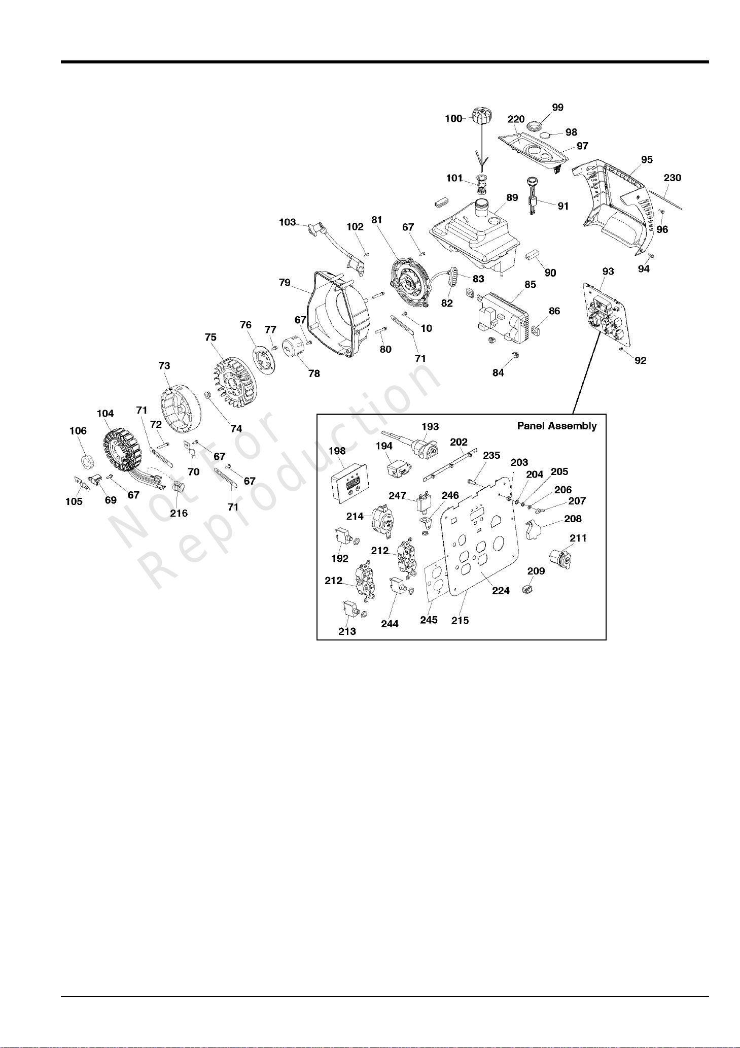
Alternator & Control Panel (800009370P1)Alternator & Control Panel (800009370P1)Alternator & Control Panel (800009370P1)Alternator & Control Panel (800009370P1)
Mfg. No: 030545-00Note: Unless noted otherwise, use the standard torque specifications
Not For
Reproduction
Copyright © Briggs and Stratton. All Rights reserved
4 12-Mar-2019
Page 5

Alternator & Control Panel (800009370P1)Alternator & Control Panel (800009370P1)Alternator & Control Panel (800009370P1)Alternator & Control Panel (800009370P1)
REF NOREF NOREF NOREF NO PART NOPART NOPART NOPART NO QTYQTYQTYQTY DESCRIPTIONDESCRIPTIONDESCRIPTIONDESCRIPTION
10 ----- SCREW
67 ----- BOLT-M6 x 12
69 705457 TRIGGER-IGNITION
70 707320 BRACKET
71 707319 * BRACKET
72 ----- SCREW-M6 x 60
73 705458 ROTOR
74 ----- NUT, FLANGE M14
75 705459 FAN
76 ----- TERMINAL
77 ----- BOLT-M6 x 16
78 705466 CUP-FLYWHEEL
79 ----- COVER-FAN
80 ----- BOLT-M6 x 55
81 705465 STARTER-REWIND
82 ----- GRIP
83 ----- INSERT-GRIP
84 ----- MOUNT-VIBRATION
85 705462 INVERTER
86 ----- MOUNT-VIBRATION
89 319939GS TANK-FUEL
90 319941GS MOUNT-VIBRATION
91 319933GS GAUGE
92 ----- SCREW
93 319922GS PANEL-CONTROL
94 ----- SCREW-M5 x 30
95 319927GS COVER-PANEL
96 ----- SCREW-M6 x 56
97 319929GS TRAY-FUEL
98 706134 PLUG-SIGHT
99 705490 GROMMET-FUEL
100 317134GS CAP-FUEL
101 317441GS FILTER, Filler Neck
102 ----- SCREW
103 705463 COIL-IGNITION
104 705464 STATOR
105 ----- BRACKET
106 ----- SEAL-OIL
192 311444GS BREAKER, Circuit
193 705488 PORT-PARALLEL
194 319946GS PORT-USB
198 705482 MODULE
202 319945GS PCB-LED
203 207743GS NUT
204 91719GS WASHER
205 207806GS WASHER
Not For
Reproduction
206 207805GS WASHER
207 187424GS NUT, WING, M5 X 0.8
208 705478 COVER-PORT
209 311442GS SWITCH
211 314531GS OUTLET, 12VDC
Copyright © Briggs and Stratton. All Rights reserved
5 12-Mar-2019
Page 6
Alternator & Control Panel (800009370P1)Alternator & Control Panel (800009370P1)Alternator & Control Panel (800009370P1)Alternator & Control Panel (800009370P1)
Mfg. No: 030545-00Note: Unless noted otherwise, use the standard torque specifications
Not For
Reproduction
Copyright © Briggs and Stratton. All Rights reserved
6 12-Mar-2019
Page 7

Alternator & Control Panel (800009370P1)Alternator & Control Panel (800009370P1)Alternator & Control Panel (800009370P1)Alternator & Control Panel (800009370P1)
REF NOREF NOREF NOREF NO PART NOPART NOPART NOPART NO QTYQTYQTYQTY DESCRIPTIONDESCRIPTIONDESCRIPTIONDESCRIPTION
212 68759GS OUTLET, 120V, 20Amp, Duplex
213 705931 CIRCUIT BREAKER, 20A
214 705932 OUTLET
215 705933 PANEL-CONTROL
216 ----- COVER-RUBBER
220 705934 DECAL
224 771888 DECAL
230 705936 DECAL
235 76040GS SCREW
244 706175 BREAKER-CIRCUIT
245 706177 INSULATION
246 706176 BRACKET
247 706178 BREAKER-CIRCUIT
-- 187876GS CABLE, BATTERY CHARGE
-(Not Illustrated)
-- 706357 FUNNEL
-(Not Illustrated)
-- 707499 ADAPTER-RV
-(Not Illustrated)
-- 100005GS OIL BOTTLE
-(Not Illustrated)
-- 703574 KIT, Tool
-(Not Illustrated)
-- 706139 JET-MAIN, High Altitude, 5000 ft
-(Optional Accessory)
Not For
Reproduction
Copyright © Briggs and Stratton. All Rights reserved
7 12-Mar-2019
Page 8

Engine (80009370_80018512_P3)Engine (80009370_80018512_P3)Engine (80009370_80018512_P3)Engine (80009370_80018512_P3)
Mfg. No: 030545-00Note: Unless noted otherwise, use the standard torque specifications
Not For
Reproduction
Copyright © Briggs and Stratton. All Rights reserved
8 12-Mar-2019
Page 9

Engine (80009370_80018512_P3)Engine (80009370_80018512_P3)Engine (80009370_80018512_P3)Engine (80009370_80018512_P3)
REF NOREF NOREF NOREF NO PART NOPART NOPART NOPART NO QTYQTYQTYQTY DESCRIPTIONDESCRIPTIONDESCRIPTIONDESCRIPTION
40 ----- SCREW
41 319930GS GUARD-MUFFLER
42 705962 GASKET
43 ----- BOLT-M6 x 75
44 ----- MUFFLER
45 ----- BOLT-M6 x 30
46 ----- COVER-CRANKCASE
50 705963 GASKET-CRANKCASE
51 ----- ROD
52 ----- COVER
53 ----- CRANKSHAFT
54 ----- PIN
55 ----- SPRING
56 ----- ARM-TENSION
57 ----- SCREW
58 ----- BRACKET
59 ----- PIN
60 ----- PIN
61 ----- BOLT-M5 x 14
62 705964 SENSOR-OIL
65 ----- COVER
96 ----- SCREW
107 ----- CRANKCASE
108 ----- GASKET
109 ----- PIN
110 ----- ROD
111 ----- PISTON
112 ----- RETAINER-PIN
113 ----- RING
114 ----- RING
115 ----- RING
116 ----- VALVE-INTAKE
117 ----- VALVE-EXHAUST
118 ----- CYLINDER HEAD
119 ----- ARM-INTAKE VALVE
120 ----- PIN
121 ----- ARM-EXHAUST VALVE
122 ----- BOLT-M8 x 50
123 705455 SPARKPLUG
124 ----- BLOCK
127 ----- O-RING
128 ----- PIN-SHAFT
129 ----- CAM-ASSEMBLY
130 ----- BOLT-M8 x 70
131 ----- SPRING
132 ----- SEAT-VALVE
Not For
Reproduction
133 ----- SEAL-VALVE OIL
134 705456 COVER-CYLINDER
135 ----- BOLT-M6 x 25
136 ----- MOUNT-VIBRATION
137 319943GS BRACKET
Copyright © Briggs and Stratton. All Rights reserved
9 12-Mar-2019
Page 10

Engine (80009370_80018512_P3)Engine (80009370_80018512_P3)Engine (80009370_80018512_P3)Engine (80009370_80018512_P3)
Mfg. No: 030545-00Note: Unless noted otherwise, use the standard torque specifications
Not For
Reproduction
Copyright © Briggs and Stratton. All Rights reserved
10 12-Mar-2019
Page 11

Engine (80009370_80018512_P3)Engine (80009370_80018512_P3)Engine (80009370_80018512_P3)Engine (80009370_80018512_P3)
REF NOREF NOREF NOREF NO PART NOPART NOPART NOPART NO QTYQTYQTYQTY DESCRIPTIONDESCRIPTIONDESCRIPTIONDESCRIPTION
138 ----- MOUNT-VIBRATION
139 ----- BUSHING
140 ----- GASKET
141 ----- BOLT-M8 x 30
142 ----- BUSHING
143 ----- MOUNT-VIBRATION
144 319935GS BRACKET
145 ----- BOLT-M5 x 25
146 319937GS HANDLE
147 ----- SCREW
148 311431GS BUSHING
149 ----- PIN-PISTON
151 ----- BRACKET
152 ----- BRACKET
153 ----- CHAIN
158 705966 GASKET
159 ----- BOLT-M6 x 20
160 ----- PIPE-MUFFLER
161 705468 GASKET
191 ----- BEARING
217 703189 ARRESTOR-SPARK
Not For
Reproduction
Copyright © Briggs and Stratton. All Rights reserved
11 12-Mar-2019
Page 12

Main Unit (80009370_80018512_P2)Main Unit (80009370_80018512_P2)Main Unit (80009370_80018512_P2)Main Unit (80009370_80018512_P2)
Mfg. No: 030545-00Note: Unless noted otherwise, use the standard torque specifications
Not For
Reproduction
Copyright © Briggs and Stratton. All Rights reserved
12 12-Mar-2019
Page 13

Main Unit (80009370_80018512_P2)Main Unit (80009370_80018512_P2)Main Unit (80009370_80018512_P2)Main Unit (80009370_80018512_P2)
REF NOREF NOREF NOREF NO PART NOPART NOPART NOPART NO QTYQTYQTYQTY DESCRIPTIONDESCRIPTIONDESCRIPTIONDESCRIPTION
1 311375GS BOLT
2 319926GS PANEL-ACCESS
3 311377GS COVER, Knob
4 ----- SCREW
5 705472 KNOB
6 ----- SCREW
7 319936GS PLATE-TRIM
8 319925GS COVER-SIDE
9 311383GS PUMP, Fuel
10 ----- SCREW
11 311384GS VALVE, Fuel
12 311385GS SWITCH, ON/OFF
13 ----- COVER-SWITCH
14 ----- SCREW
15 311386GS SCREW
16 705474 COVER-AIR CLEANER
17 705473 FILTER-A/C FOAM
18 705475 FILTER-A/C FOAM
19 705476 BASE-AIR CLEANER
20 317446GS HOSE
21 317108GS CHECK VALVE
22 317447GS HOSE
23 ----- BOLT-M5 x 12
24 ----- NUT
25 ----- SLEEVE
26 705477 COVER-AIR CLEANER
27 705939 GASKET-AIR CLEANER
28 705940 CARBURETOR
29 ----- ROD-THROTTLE
30 ----- SPRING
31 705944 BRACKET
32 ----- SCREW
33 ----- SCREW
34 705938 MOTOR-STEPPER
35 705941 COVER
36 705945 GASKET
37 705942 STUD
38 705495 INSULATOR
39 705496 GASKET
63 705491 DIPSTICK
64 705492 OIL SEAL
66 ----- DEFLECTOR
67 ----- BOLT-M6 x 12
68 ----- SEAL-RUBBER
107 ----- CRANKCASE
150 ----- DEFLECTOR
Not For
Reproduction
154 705467 REGULATOR-VOLTAGE
155 ----- NUT
156 319924GS COVER-SIDE
157 319928GS COVER-SPARK PLUG
162 706065 HUBCAP
Copyright © Briggs and Stratton. All Rights reserved
13 12-Mar-2019
Page 14

Main Unit (80009370_80018512_P2)Main Unit (80009370_80018512_P2)Main Unit (80009370_80018512_P2)Main Unit (80009370_80018512_P2)
Mfg. No: 030545-00Note: Unless noted otherwise, use the standard torque specifications
Not For
Reproduction
Copyright © Briggs and Stratton. All Rights reserved
14 12-Mar-2019
Page 15

Main Unit (80009370_80018512_P2)Main Unit (80009370_80018512_P2)Main Unit (80009370_80018512_P2)Main Unit (80009370_80018512_P2)
REF NOREF NOREF NOREF NO PART NOPART NOPART NOPART NO QTYQTYQTYQTY DESCRIPTIONDESCRIPTIONDESCRIPTIONDESCRIPTION
163 ----- BOLT-M6 x 25
164 319932GS BAR
165 319934GS BRACKET
166 319942GS FRAME
167 ----- NUT-FLANGE M8
168 705469 MOUNT-VIBRATION
169 705494 AXLE
170 705946 BRACKET
171 705470 MOUNT-VIBRATION
172 771593 E-RING
173 705471 SLEEVE
174 ----- BOLT-M8 x 16
175 319938GS HANDLE
176 319923GS COVER-BOTTOM
177 311427GS MOUNT, Vibration
178 319940GS WHEEL
179 311426GS MOUNT, Vibration
180 705483 HOSE
181 705484 HOSE
182 705487 SEPARATOR
183 705485 HOSE
184 705486 HOSE-FUEL
185 ----- CLAMP
186 705480 HOSE-FUEL
187 705481 HOSE-FUEL
188 ----- CLAMP
189 705479 HOSE-FUEL
190 705493 FILTER
218 705977 DECAL
219 705968 DECAL
223 705967 DECAL
225 705978 DECAL
231 705976 DECAL
Not For
Reproduction
Copyright © Briggs and Stratton. All Rights reserved
15 12-Mar-2019
Page 16

Wiring Diagram (319944WD)Wiring Diagram (319944WD)Wiring Diagram (319944WD)Wiring Diagram (319944WD)
Mfg. No: 030545-00Note: Unless noted otherwise, use the standard torque specifications
Not For
Reproduction
Copyright © Briggs and Stratton. All Rights reserved
16 12-Mar-2019
Page 17

Wiring Diagram (319944WD)Wiring Diagram (319944WD)Wiring Diagram (319944WD)Wiring Diagram (319944WD)
REF NOREF NOREF NOREF NO PART NOPART NOPART NOPART NO QTYQTYQTYQTY DESCRIPTIONDESCRIPTIONDESCRIPTIONDESCRIPTION
-- ----- Wiring Diagram Only
-- WARNING Warning Generator Voltage Could Cause Electrical Shock or Burn Resulting in
Death Or Serious Injury. To Avoid Electrical Shock Or Burn Hazard, Please Refer
Service To Qualified Personnel.
Not For
Reproduction
Copyright © Briggs and Stratton. All Rights reserved
17 12-Mar-2019
Page 18

Wiring Schematic (319944WS)Wiring Schematic (319944WS)Wiring Schematic (319944WS)Wiring Schematic (319944WS)
Mfg. No: 030545-00Note: Unless noted otherwise, use the standard torque specifications
Not For
Reproduction
Copyright © Briggs and Stratton. All Rights reserved
18 12-Mar-2019
Page 19

Wiring Schematic (319944WS)Wiring Schematic (319944WS)Wiring Schematic (319944WS)Wiring Schematic (319944WS)
REF NOREF NOREF NOREF NO PART NOPART NOPART NOPART NO QTYQTYQTYQTY DESCRIPTIONDESCRIPTIONDESCRIPTIONDESCRIPTION
----- Wiring Schematic Only
WARNING Warning Generator Voltage Could Cause Electrical Shock or Burn Resulting in
Death Or Serious Injury. To Avoid Electrical Shock Or Burn Hazard, Please Refer
Service To Qualified Personnel.
Not For
Reproduction
Copyright © Briggs and Stratton. All Rights reserved
19 12-Mar-2019
Page 20

in/lbs
ft/lbs
3
Torque Specification Chart
FOR STANDARD METRIC MACHINE HARDWARE (Tolerance ± 20%)
Property
Class
Class 8.8
Class 10.9
Class 12.9
Size Of
Hardware
Nm. Nm. Nm.
Nm.
M3 1.28
2.90
5.75
9.9
16.5
24
48
83
132
200
275
390
530
375
995
1350
1830
2360
3050
13.44 1.80
4.10
8.10
14
23
34
67
117
185
285
390
550
745
960
1400
1900
2580
3310
4290
19.2 22.92 2.15
M4 30.72 43.44 52.56 4.95
M5 60.96 5.97 7.15
16.5
9.7
M6 7.3 10.3 12.1
M7 12.1 16.9 19.9
27
M8 17.7
25
29
40
M10 35 50
59
81
M12 61 86.2 103 140
M14
101
136 162 220
M16 147 210 250 340
M18 202 287 346 470
M20 290 405 486 660
M22 390 559 656 890
M24 497
708
840 1140
M27 733 1032 1239 1680
M30 995 1401 1681 2280
M33
1349
1902 2278 3090
M36 1740 2441
3798
2935 3980
M39 2249 3163
Torque Specification Chart
FOR STANDARD MACHINE HARDWARE (Tolerance ± 20%)
Hardware
Grade
SAE Grade 2 SAE Grade 5 SAE Grade 8
Size Of
in/lbs
ft/lbs
in/lbs
ft/lbs
in/lbs
ft/lbs
in/lbs in/lbs
Hardware ft/lbs Nm. ft/lbs Nm. ft/lbs Nm.
8-32 19 2.1 30 3.4 41 4.6
8-36 20 2.3 31 3.5 43 4.9
10-24 27 3.1 43 4.9 60 6.8
10-32 31 3.5 49 5.5 68 7.7
1/4-20 66 7.6 8 10.9 12 16.3
1/4-28 76 8.6 10 13.6 14 19.0
5/16-18 11 15.0 17 23.1 25 34.0
5/16-24 12 16.3 19 25.8 29 34.0
3/8-16 20 27.2 30 40.8 45 61.2
3/8-24 23 31.3 35 47.6 50 68.0
7/16-14 30 40.8 50 68.0 70 95.2
7/16-20 35 47.6 55 74.8 80 108.8
1/2-13 50 68.0 75 102.0 110 149.6
1/2-20 55 74.8 90 122.4 120 163.2
9/16-12 65 88.4
110 149.6 150 204.0
9/16-18 75 102.0 120 163.2 170 231.2
5/8-11 90 122.4 150 204.0 220 299.2
5/8-18 100 136 180 244.8 240 326.4
3/4-10 160 217.6 260 353.6 386 525.0
3/4-16 180 244.8 300 408.0 420 571.2
7/8-9 140 190.4 400 544.0 600 816.0
7/8-14 155 210.8 440 598.4 660 897.6
1-8 220 299.2 580 788.8 900 1,244.0
1-12 240 326.4 640 870.4 1,000 1,360.0
Hex Head Capscrew
Hex Nut
Lockwasher
Washer
Carriage Bolt
NOTES
1. These torque values are to be used for all hardware
excluding: locknuts, self-tapping screws, thread forming
screws, sheet metal screws and socket head setscrews.
2. Recommended seating torque values for locknuts:
a. for prevailing torque locknuts - use 65% of grade 5
torques.
b. for flange whizlock nuts and screws - use 135% of
grade 5 torques.
3. Unless otherwise noted on assembly drawings, all torque
values must meet this specification.
Hardware Identification & Torque Specifications
Common Hardware Types
No
Marks
The guides and ruler furnished below are designed to
help you select the appropriate hardware.
8.8
10.9
12.9
Class 5.6
5.6
5150
13.44
1.28
5.88
26.4
2.50
44.64
4.3
5.2
7.1
7.7
10.5
15
21
988
1340
759
1030
590
800
435
590
320
435
217
295
169
230
126
171
89
121
64
88
42
58
26
36
.56
Thread
Diameter (mm)
Screw, 1/2- 16 x 2
Body
Diameter
Diameter
Inside
Diameter (in)
Nut, 1/2-16
0
1/4 3/4
1/2
21
1/4 3/4
1/2
1/4 3/4
1/2
1/4 3/4
1/2
4
90
100
70
80
50
60
30
40
010
20
Thread
Diameter (mm)
Nut, M8
Screw, M8- 1.25 x 25
Distance between
threads (mm)
Body
Length (in)
Body
Length (mm)
3/8” Bolt or Nut
Wrench—9/16”
5/16” Bolt or Nut
Wrench—1/2”
1/4” Bolt or Nut
Wrench—7/16”
1/2” Bolt or Nut
Wrench—3/4”
7/16” Bolt or Nut
Wrench (Bolt)—5/8”
Wrench (Nut)—11/16”
in/lbs
Threads
per inch
Threads
per inch
Body Length
Body
When a washer or nut is identified as
1/2”
(M8), this is
the Nominal size, meaning the inside diameter is 1/2 inch
(8mm metric thread diameter); if a second number is present
it represents the threads per inch (distance between threads).
When bolt or capscrew is identified as
1/2 - 16 x 2” (M8 - 1.25 x 50),
this means the Nominal size, or body diameter is 1/2 inch (8mm
metric thread diameter), the second number,16, represents the
threads per inch, (distance between threads). The final number
is the body length of the bolt or screw, 2 inches (50mm).
Standard Hardware Sizing
M6 Bolt or Nut
Wrench—10mm
M8 Bolt or Nut
Wrench—13mm
M10 Bolt or Nut
Wrench—17mm
M12 Bolt or Nut
Wrench—19mm
M14 Bolt or Nut
Wrench—22 mm
Wrench & Fastener Size Guide
Page 21

Copyright © Briggs and Stratton. All Rights reserved
12-Mar-2019
 Loading...