

Page 1
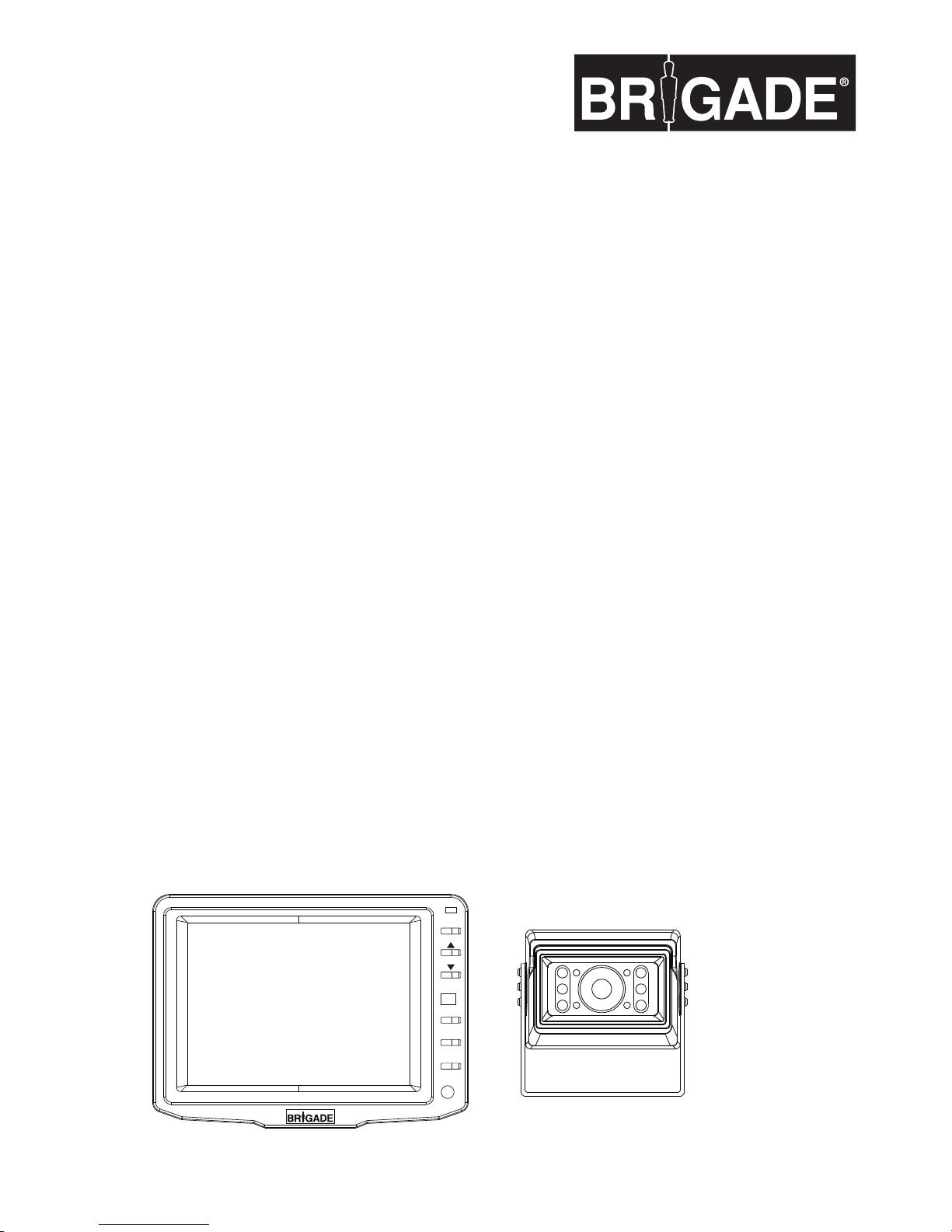
VBV-650 VEHICLE CCTV SYSTEM
VBV-650M MONITOR VBV-600C CAMERA
ISSUE 1 - November 2008
POWER
MENU
SEL
AV/CA
Page 2
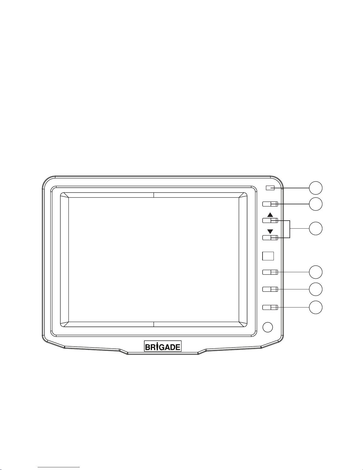
Front view
1. Power LED
2. Power ON/OFF Switch
3. s+t CONTROL BUTTON
4. MENU
5. SELECT
6. CAMERA CA/AV
POWER
MENU
SEL
AV/CA
1
2
4
5
6
3
Page 3

INTRODUCTION
This vehicle CCTV system has been designed to provide
years of trouble-free operation. Please read this manual
thoroughly. This manual contains instructions to make the
installation of the camera and monitor easier. The vehicle
CCTV system is a supplement to standard rear-view mirror
systems, and will provide additional rear-view vision when
installed and maintained properly.
It is not intended in any way to be a substitute for careful
and cautious driving.
All applicable trafc laws and motor safety regulations must
still be adhered to.
FEATURES
VBV-600C CAMERA
• 300,000 pixel image sensor
• 0.1 Lux sensitivity (10 IR-LED)
• Auto White Balance (AWB)
• Field of view 120° Diagonal
• Back Light Compensation (BLC)
• Automatic electronic iris provides a clearer, more
consistent image in low and bright light
• Compact and lightweight design installed easily into
most vehicles
• Waterproof cable connection (IP67)
• EMC approved
VBV-650M TFT LCD COLOUR 5.0" (127mm) MONITOR
• Menu button for Picture, System and Options
• Camera 1/AV (Audio on AV channel only)
• Power/stand-by switch
• EMC approved
CONTENTS OF 1 COMPLETE SYSTEM
VBV-600C CCD CAMERA
1 Camera
1 Camera bracket
4 Attachment screws with washers
VBV-650M MONITOR
1 VBV-650M MONITOR
1 Monitor bracket
BEFORE INSTALLATION
1. This system operates from 10 volts DC to 32 volts DC,
negative ground.
2. Please install this system according to the instructions
in this manual.
3. Do not disassemble the camera or the monitor. This
voids the warranty. Disassembling the camera will
compromise the waterproof seal.
4. Connect the system to an ignition switched power
source. Connection to a battery source will reduce
battery life.
WARNING
1. To prevent electrical shock, DO NOT OPEN THE
MONITOR CASE.
There are potentially lethal voltages inside the monitor.
There are no user serviceable parts inside. If evidence of
tampering is detected, the warranty will be considered
void.
2. Keep monitor away from leaking water, rain, moisture
etc. It is NOT waterproof. Any moisture inside the
monitor could cause extensive damage.
3. Use the self-tapping screws to mount the monitor to the
dashboard or headliner.
INSTALLATION INSTR UCTIONS
VBV-600C CAMERA
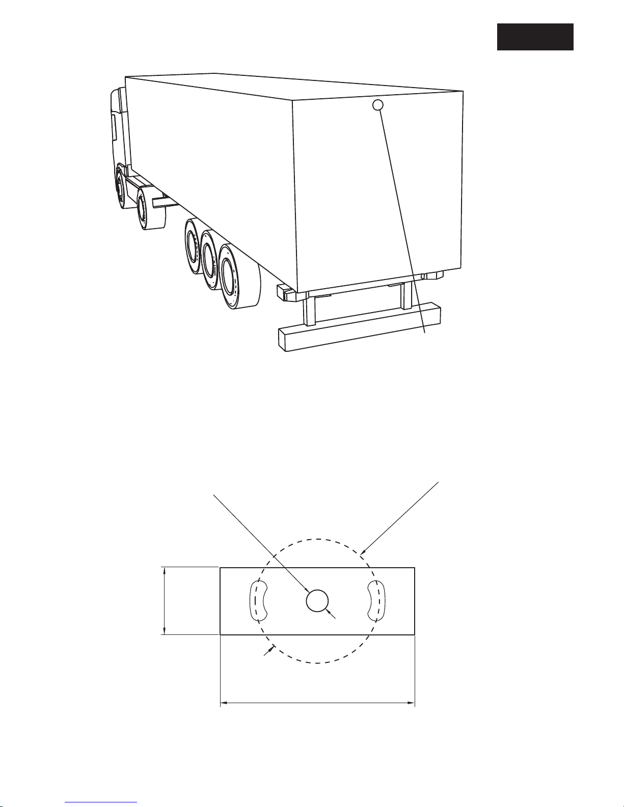
1. Attach camera bracket (see Fig. 1) to upper portion of
vehicle. Attachment point must be sturdy enough to
support camera and bracket.
2. Attach camera to bracket using screws provided. Adjust
angle as indicated in Fig. 2. (Use rear bumper and back
of vehicle as a reference point.)
VBV-650M MONITOR
1. Attach monitor inside vehicle in a location convenient to
the driver (e.g. centre of dash, overhead or in dash).
3.
Adjust mounting angle of the monitor to allow driver to
easily view the screen from all seat positions. (See Fig. 3.)
CABLE
1. The camera to cable connection is waterproof. Be sure
to position the cable properly. The male end attaches to
the camera. The female end attaches to the main power
cable. (See Fig. 4.)
2. Do not run the cable over sharp edges or corners. Do
not kink the cable. Keep the cable away from hot and
rotating parts.
3. Place all excess cable in convoluted tubing.
4. Wire the cable securely.
WIRING CAMERA AND MONITOR
1. See wiring diagram for connections to ignition, ground
and back up circuit. (See Fig. 4.)
2. Wiring camera: Drill a 20mm (0.8in) diameter hole into
vehicle body near the camera and bracket. Connect
camera connector to extension cable in vehicle. Push
extra cable into vehicle (be careful not to kink cable) and
t grommet into hole. Apply sealant around grommet to
increase resistance to water penetration.
3. Wiring the monitor: Insert extension cable into Camera1
reversing camera position; if AV is used be sure to
have the correct cable. DO NOT bundle excess cable
together. Use a cable tie or vinyl tape. This will avoid
possible damage to cable during operation.
4. The red wire is connected to an ignition power source,
the black wire is connected to chassis ground, the
brown wire is connected to the vehicle’s back light
circuit.
5. ONLY PETROLEUM ROAD TANKE RS: All electrical
equipment tted to petroleum vehicles must be tted
via battery master switch and must be isolated from the
battery while the vehicle are loading and unloading.
6. Always consult your dealer when tting any electrical or
electronic equipment to a vehicle tted with a CAN-bus
or multiplex system.
FUNCTIONS AND OPERATION
MONITOR
1. POWER LED
When the red LED is on, it indicates power on
When a trigger is selected, the image shown by cameras
will be shown on the monitor
2. Stand by ON/OFF Switch
3. s/t CONTROL BUTTON
These control buttons are used to scroll up and down to
select menu options
4. SEL
SELECT CONTROL BUTTON
Use these buttons in order to select the required option
in the menus.
5. ‘MENU’ Button
If you press the ‘MENU’ button, the following list of
functions will be shown on the monitor
• PICTURE
• OPTION
• SYSTEM
The menu list will disappear if no selection is chosen
within 5 seconds.
6. AV/CA
Camera selector button
Enables selection of CA1 & AV
The OSD indicates which camera is currently operating.
HOW TO SET YOUR MONITOR TO YOUR
REQUIREMENTS
1. PICTURE CONTROL
1.1 Press the MENU button
1.2 Select PICTURE
1.3 Move the cursor to the CONTRAST, BRIG HT, COLOUR
and SHARP with the SEL button
1.4 Press the s/t button
1.5 Select one of four options
1.6 Press the ‘MENU’ button
2. OPTION CONTROL
2.1 Press the ‘MENU’ button
2.2 Select ‘OPTION’
2.3 Move the cursor to the HORIZONTAL and VERTICAL
(Switch the picture) with the SEL button
2.4 Press the s/t button
2.5 Select one of two option
3. SYSTEM CONTROL
3.1 Press the ‘MENU’ button
3.2 Select ‘SYSTEM’
3.3 Move the cursor to the INPUT, (CA or AV) COLOUR
SYSTEM (NTSC/PAL/AUTO) and LANGUAGE with the
SEL button.
3.4 Press the s/t button
3.5 Select one of three options
4.0 AV Model (Audio)
4.1 Press the AV/CA to select the AV function
4.2 Press the s/t button to adjust volume.
CAUTION
1. DO NOT OPEN THE CAMERA CASE. This will
break the camera’s waterproof seal. If evidence of
tampering is detected, the warranty will be considered
void.
2. We do not recommend mounting the camera near the
lower area of the vehicle (e.g. bumper). This reduces the
view of the camera and increases the chance of physical
damage to the camera.
3. Use only the inner hexagonal screw and washers to
mount the camera.
MAINTENANCE
Remove dust and dirt with a damp soft cloth. Heavier
dirt should be removed with a damp soft cloth and mild
detergent. Do not use strong cleaning agents containing
gasoline, thinner, benzene or alcohol.
These substances may damage the exterior surface of
the monitor.
CAUTION
1. Before drilling, be sure no cable or wire is on the other
side. Be sure to drill a 20mm (0.8in) diameter hole only.
2. Feed as much cable as possible into vehicle and clamp
securely. This reduces the possibility of it being hooked
or snagged.
3. Keep all cables away from HOT, ROTATING and
ELECTRICALLY NOISY components.
4. To increase protection of cable, place all excess wire
and extension cable in convoluted tubing.
5. Do not twist camera cable and do not cut camera pigtail
or cable
SPECIFICATIONS
VBV-600C CAMERA
TV SYSTEM PAL/NTSC
PICTURE ELEMENTS 512(H) x 582(V) PAL
512(H) x 492(V) NTSC
SENSING AREA 2.8mm
IMAGE SIZE 1/4 inch
SYNCHRONIZATION INTERNAL
HORIZONTAL RESOLUTION 420 TV LINES
REQUIRED ILLUMINATION 0.1 LUX MINIMUM
SIGNAL TO NOISE RATIO MINIMUM 48dB
(AT AGC OFF)
POWER SUPPLY 12Vdc
CURRENT CONSUM PTION MAX. 80mA
LENS ANGLE 120º(D), 96º(H), 72º(V)
OPERATION TEMPERATURE -10ºC TO +70ºC
STORAGE TEMPERATURE -20ºC TO +80ºC
WEIGHT 224g
DIMENSIONS (WxHxD) 2.0x1.5x2.0in
(52.3x40.3x54mm)
VBV-650M MONITOR
PICTURE TUBE 5.0 inch (127mm),
COLOUR TFT-LCD
DEFLECTION ANGLE 50°(LEFT/R IGHT),
15°(TOP), 35°(DOWN)
POWER CONSUMPTION 8W/650mA
POWER SOURCE 12/24Vdc
TV SYSTEM PAL/NTSC
VIDEO INPUT/OUTPUT COMPOSITE VIDEO
SINGLE
1VP-P 75 OHM
RESOLUTION 960(H) x 234(V)
CONTRAST 350:1
BRIGHTNESS 300cd/m2
OPERATING TEM PERATURE -10°C TO +60°C
STORAGE TEMPERATURE -20°C TO +70°C
WEIGHT 415g
OUTER DIMENSIONS (WxHxT) 5.8x4.3x1.0in
(146x107.5x25.4mm)
DISCLAIMER
The use of the VBV-650 Vehicle CCTV system should not
in any way be used as a substitute for careful and cautious
driving. Trafc laws and motor safety regulations must
always be adhered to.
Original equipment manufacture bodybuilder guide or
aftermarket installation guidelines must be followed when
installing this product.
Failure to comply with this may invalidate the vehicle’s
warranty.
Specication subject to change without any notice.
VBV-650 VEHICLE CCTV SYSTEM
Page 4
2.2in (56.5mm)
Ø 0.25" (6mm)
Ø 1.15" (29.25mm)
1in (25mm)
Fig. / Abb. 1
Mount camera assembly high mounted. (Centred.)
Camera mounting hole pattern.
Page 5
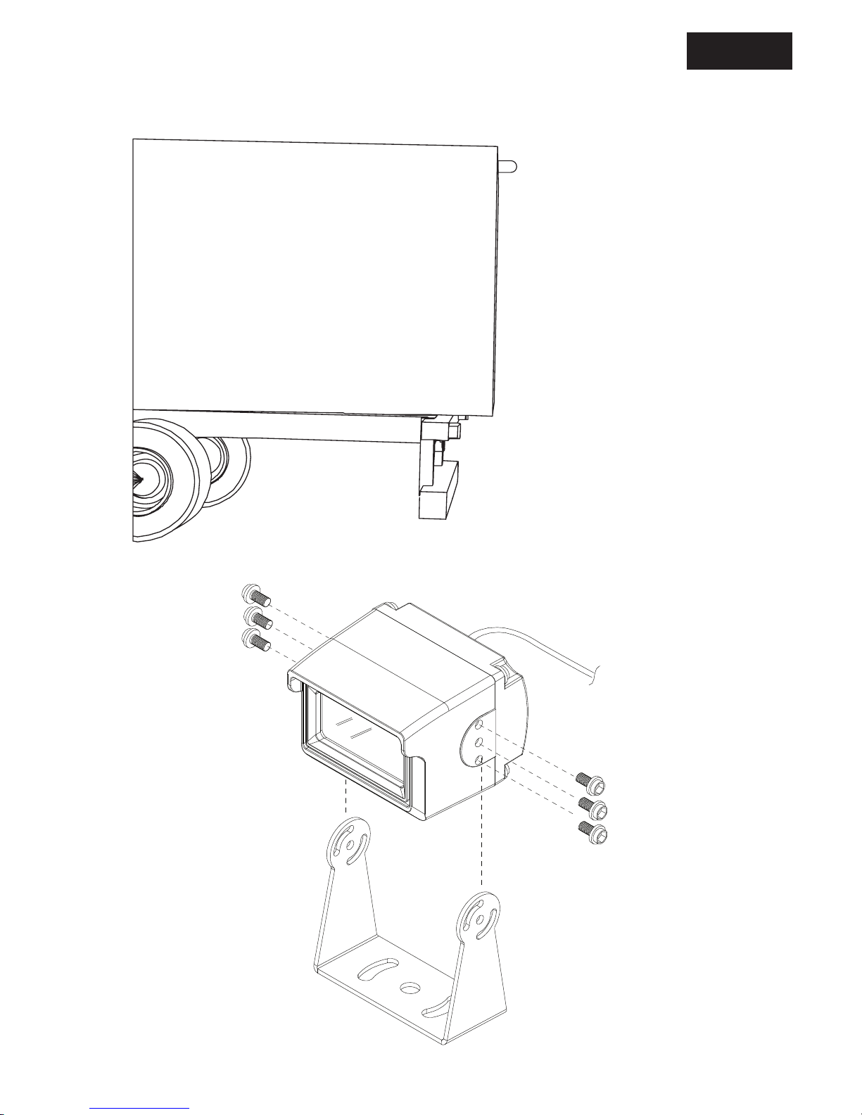
Fig. / Abb. 2
Position of camera
Page 6
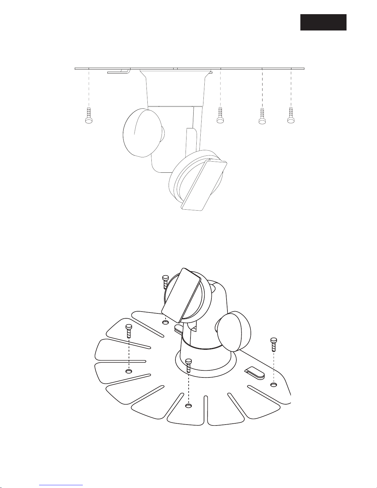
Fig. / Abb. 3
Mounting on ceiling
Mounting on the dash,
console etc.
Page 7
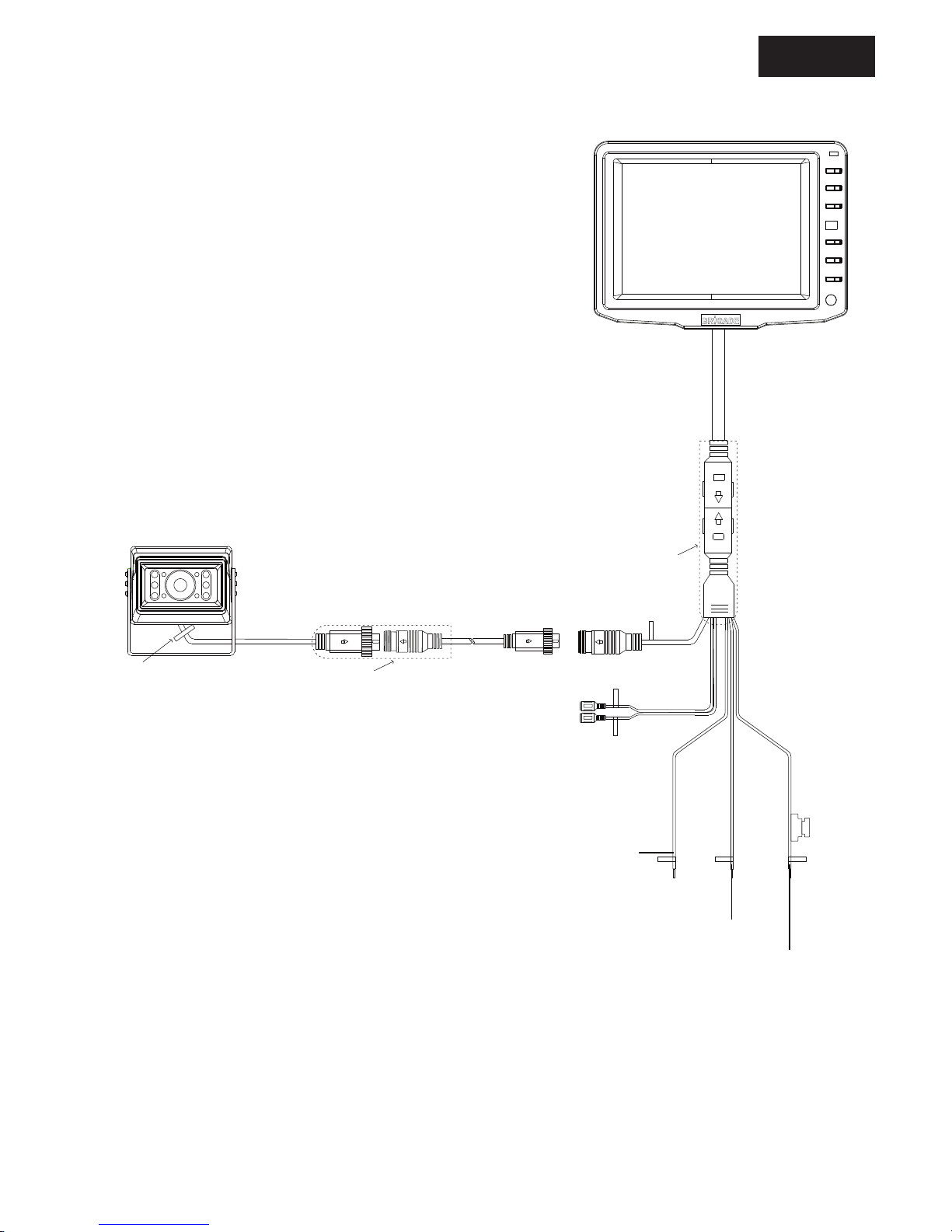
Fig. / Abb. 4
AUDIO IN
VIDEO IN
BROWN WIRE
REVERSE TRIGGER
BLACK WIRE
GROUND WIRE
RED WIRE
POWER INPUT
GROMET
PROTECTIVE BOOT
PROTECTIVE BOOT
AUDIO IN
CAMERA 1
VIDEO IN
Page 8
11.08.1983.VBV-650Kit.ML
Brigade Electronics Plc. Brigade House, The Mills, Station Road, South Darenth, DA4 9BD. United Kingdom
Tel: +44 (0)1322 420300 Fax: +44 (0)1322 420343 email: [email protected]
Brigade Electronics Inc, 202 Delaware Avenue, Suite 1, Palmerton, PA 18071 USA
Tel: +1 (610) 826-7870 Fax: +1 (484) 229-0088 email: [email protected]
Brigade Elektronik GmbH, Haberstr. 36 A, 24537 Neumünster, Germany
Telefon: +49 (0) 4321 555 362 Fax: +49 (0) 4321 555 361 email: [email protected]
Brigade Elettronica srl, Via Lucio 111 Papa 6, 55100 Lucca, Italia
Telefono: +39 (0) 329 9484702 email: [email protected]
Brigade Electronika (PTY) Ltd, P.O. Box 53203, Wierdapark 0149, South Africa
Tel: +27 (0) 72 757 7166 Fax: +27 (0) 866 963 238 email: [email protected]
Brigade Electronique Sarl, 22 Rue Pierre Bontemps, 72000 Le Mans, France
Tel: +33 (0) 2 23 61 08 97 Fax +33 (0) 2 23 61 08 97 email: [email protected]
 Loading...