

Page 1
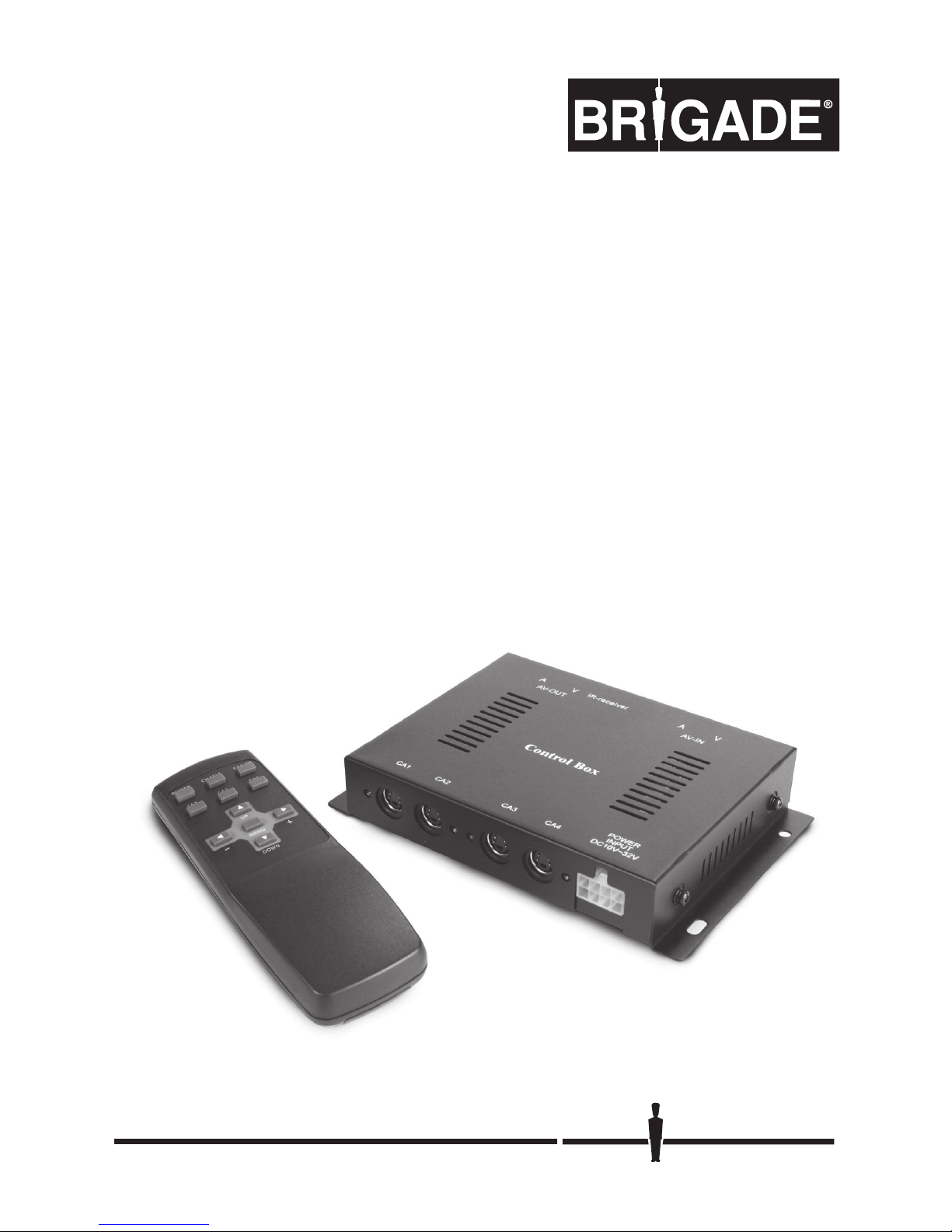
EDM-50
Multi-camera control module
User & fitting guide
Stock code #3589
Page 2
1 Contents
2
Important
The model and and serial number is located on the base of the unit. Record the serial number below.
Refer to these details whenever you call your supplier regarding this equipment.
Model No.: EDM-50
Serial No.:
WARNING
To prevent fire or shock hazard, do not expose the unit to rain or moisture. To avoid electric shock, do
not open the case. Refer servicing to qualified personnel only.
Any user made modifications not expressly approved in this manual will void your warranty.
CAUTION: TO REDUCE THE RISK OF ELECTRIC SHOCK,
DO NOT REMOVE COVER (OR BACK).
NO USER-SERVICEABLE PARTS INSIDE.
REFER SERVICING TO QUALIFIED SERVICE PERSONNEL.
CAUTION
RISK OF ELECTRIC SHOCK
DO NOT OPEN
This symbol is intended to alert the user to the presence of
uninsulated ‘dangerous voltage’ within the product’s enclosure that
may be of sufficient magnitude to constitute risk of electric shock to
persons.
This symbol is intended to alert the user to the presence of important
operating and maintenance (servicing) instructions in the literature
acompanying this appliance.
Page 3
3
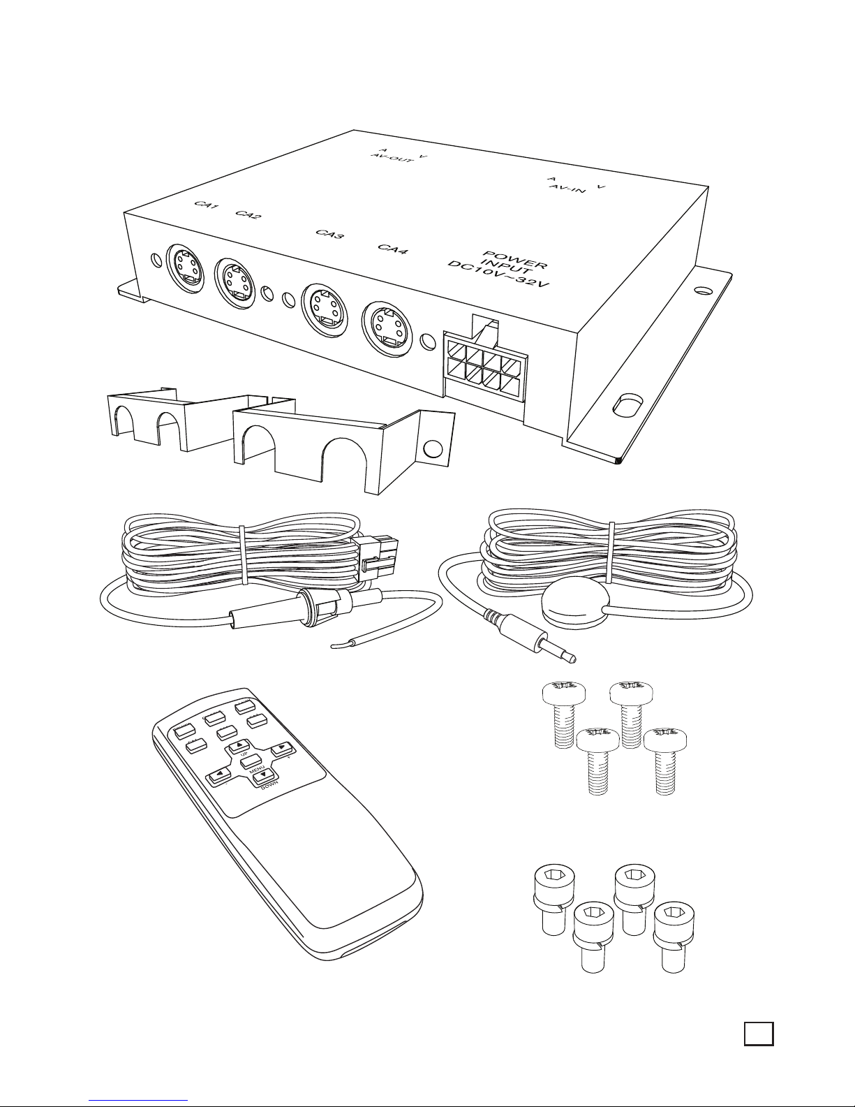
1 Contents
M4 x 15mm
M3 x 6mm
Page 4
3 System connections
4
2 Installation
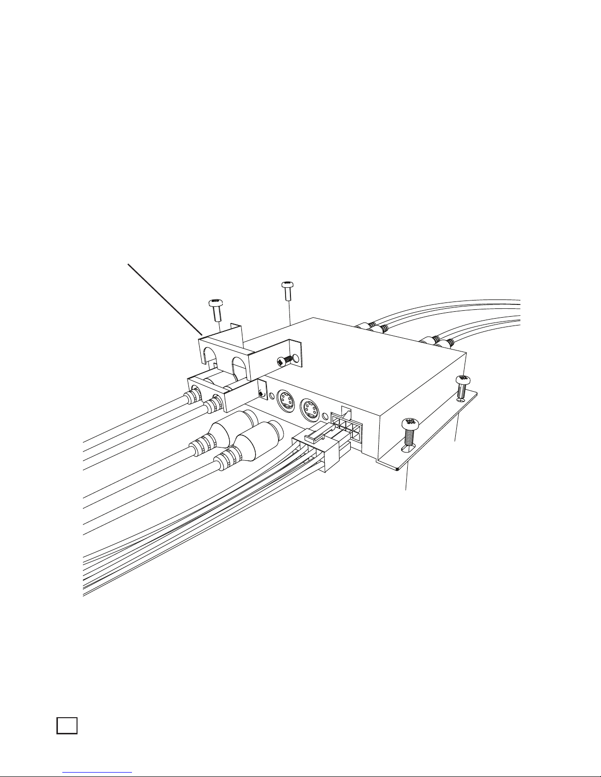
Jack bracket
Attach these brackets after
installing the camera cable to
ensure cables stay in place.
Fix the unit to a suitable flat surface away from extremes of heat, moisture, direct sunlight,
excessive dust and mechanical vibration or shock.
Page 5
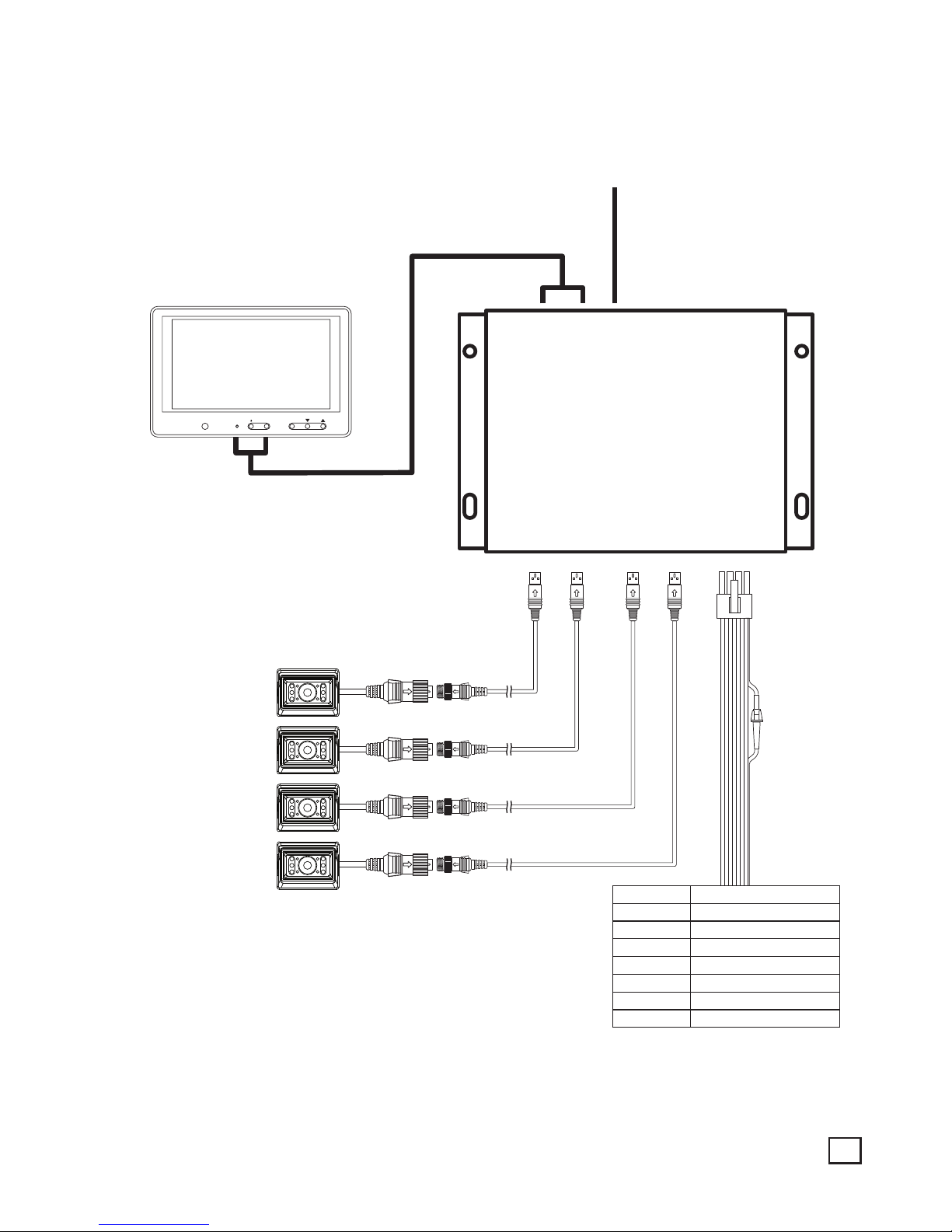
5
3 System connections
EDM-50
POWER
INPUT
10V~32V
CA1
AV-IN
IR Remote control sensor
A V
AV-OUT
A V
CA2 CA3 CA4
CA./SEL
MONITOR
MENU
RED 10~32Vdc
GREEN TRIGGER 1
WHITE TRIGGER 2
BROWN TRIGGER 5 (SPLIT)
BLACK GROUND
YELLOW TRIGGER 4
BLUE TRIGGER 3
ORANGE TRIGGER OUT
Page 6
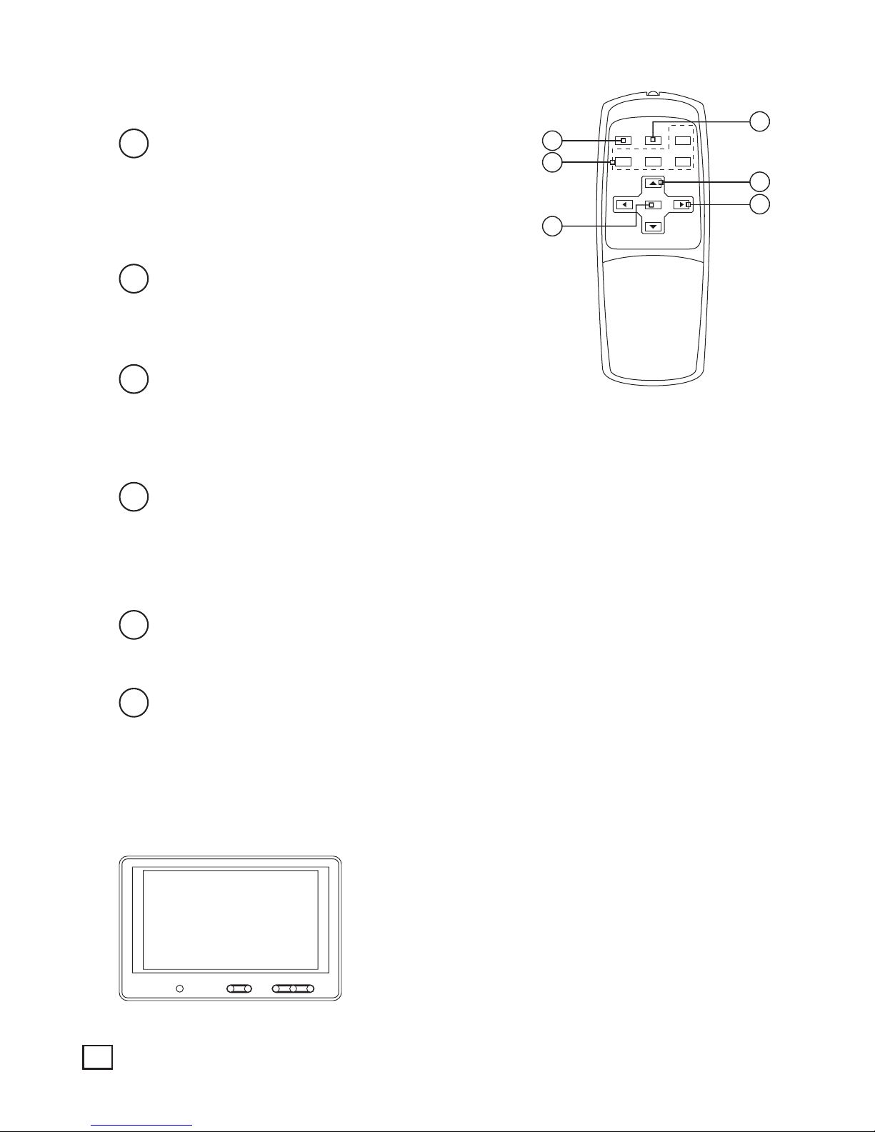
5 Operations
6
4 Remote control functions
POWER CH.SELE CA4/AV
CA1
UP
MENU
DOWN
– +
CA2 CA3
1
5
6
2
3
4
1
POWER:
Press power button to turn the control box on or off.
When the trigger signal is activated, the selected
source’s image will be displayed on the monitor screen
automatically. Please refer to TRIGGER MODE in SETUP
MENU for further information.
2
-/+:
Press -/+ button to adjust BRIGHT or CONTRAST level.
Press -/+ button to select the content of the selected line
in each sub menu.
3
UP/DOWN:
Press UP/DOWN button to adjust TILT (PAN) camera
position upward or downward. Available only when TILT (PAN) camera is connected to CA1,
CA2 or CA3 input.
Press UP/DOWN button to move the cursor up or down in SETUP MENU and each sub menu.
4
CH.SELE:
Press CH.SELE to select the display image.
Sequential pressing shows the image of each camera in turn as follows;
CAM1 - CAM2 - CAM3 - CAM4 - AUX - SPLIT1 - SPLIT2 - SPLIT3
The On Screen Display indicates which image is displayed on the screen.
5
CA1, CA2, CA3, CA4/AV:
Press CA1, CA2 or CA3 to select each camera.
Press CA4/AV to select CA4 and press again to select any AV device connected.
6
MENU:
Press MENU for less than 0.5 seconds to adjust BRIGHT or CONTRAST, COLOUR or TILT
(when tilt capable camera is connected).
Press MENU for over 1 second to enter SETUP MENU.
Use UP/DOWN to move up and down and use -/+ to move left and right in SETUP MENU and
each sub menu.
Press MENU to go back to the previous menu when in SETUP MENU or each sub menu.
MAIN MENU
1. CAMERA SETTING
2. TRIGGER MODE
3. SPLIT MODE
4. AUTO SCAN
5. ADVANCED MENU
Page 7
7
1
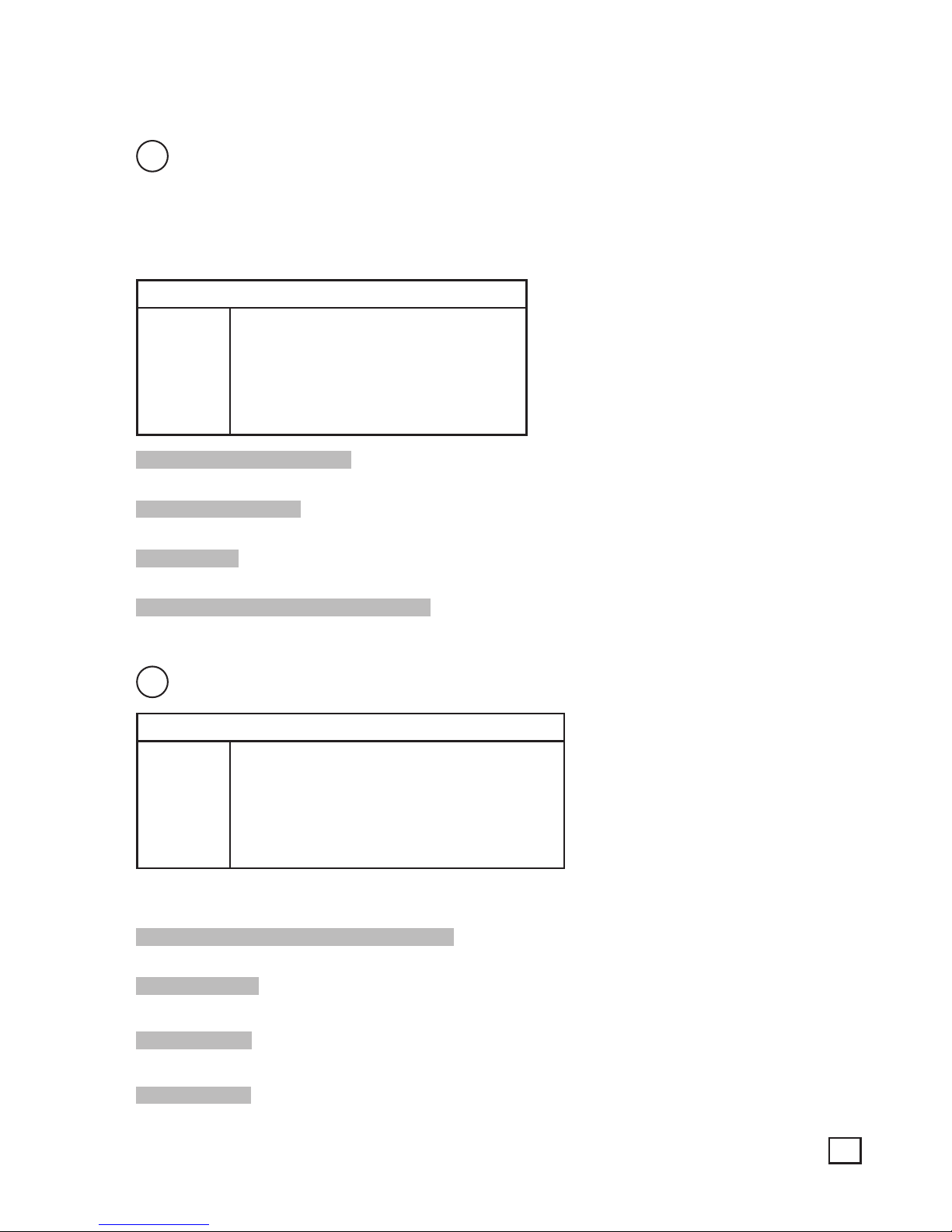
CAMERA SETTING:
Press MENU for over 1 second to enter SETUP MENU.
Use UP/DOWN to move up and down and use -/+ to move left and right in SETUP MENU and
each sub menu.
Press MENU to go back to the previous menu when in SETUP MENU or each sub menu.
1. CAMERA SETTING
CAM1
CAM2
CAM3
CAM4
NOR/MIR: [MIRROR;NORMAL]
UP/DOWN: [UP;DOWN]
NAME: [CAM1]
SORT: [NORMAL;SHUTTER;
TILT.MT;TILT.AT]
NOR/MIR: [MIRROR;NORMAL]
Each camera’s Normal/Mirror view can be selected.
UP/DOWN: [UP;DOWN]
Each camera’s converted image display (top and bottom).
NAME: [CAM1]
Change the name of the camera.
SORT:[NORMAL;SHUTTER;TILT.MT;TILT.AT]
Select different function of camera.
2
TRIGGER MODE:
2. TRIGGER MODE
TRIGGER1
TRIGGER2
TRIGGER3
TRIGGER4
TRIGGER5
SOURCE:[CAM1~CAM4; AUX1~2; SPLIT1~3]
DELAY:[0~20sec]
SCALE:[ON;OFF]
DISPLAY SCALE
Up to 5 triggers can be set and each trigger source (CAM1~SPLIT3) can be selected. When trigger is
activated, the selected source’s image is displayed.
SOURCE:[CAM1~CAM4; AUX1~2; SPLIT1~3]
Select the source item for the trigger.
DELAY:[0~20sec]
Each trigger’s delay time is adjustable from 0 to 20 seconds.
SCALE:[ON;OFF]
ON/OFF setting for distance marker when any trigger is activated.
DISPLAY SCALE
Adjustable Position and Width setting for distance marker.
5 Operations
Page 8
5 Operations
8
3
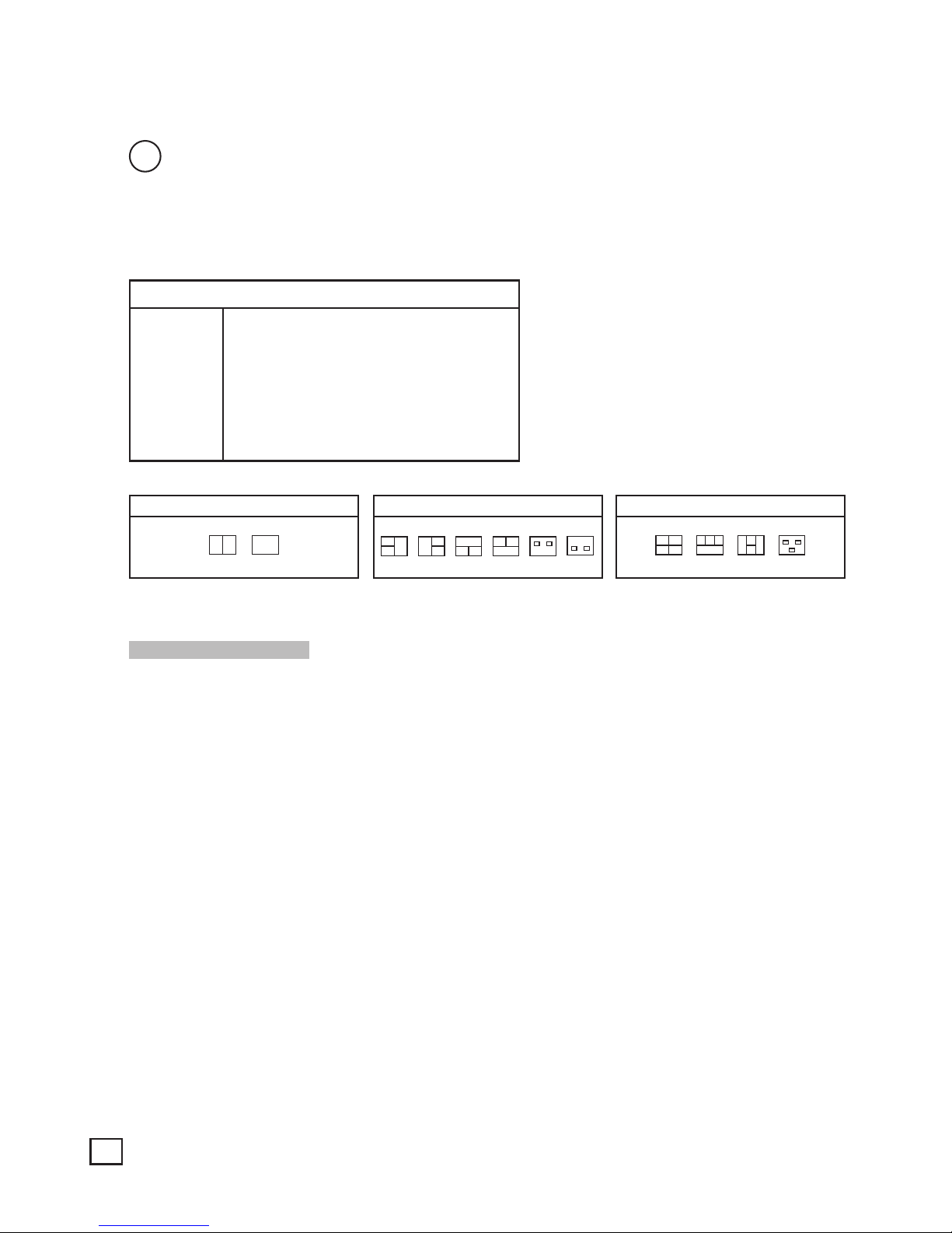
SPLIT MODE:
Press MENU for over 1 second to enter SETUP MENU.
Use UP/DOWN to move up and down and use -/+ to move left and right in SETUP MENU and
each sub menu.
Press MENU to go back to the previous menu when in SETUP MENU or each sub menu.
3. SPLIT MODE
SPLIT1
SPLIT2
SPLIT3
SOURCE1:[CAM1~4;OFF]
SOURCE2:[CAM1~4;OFF]
SOURCE3:[CAM1~4;OFF]
SOURCE4:[CAM1~4;OFF]
AUDIO:[CAM1~4;OFF]
TYPE:[DEFAULT;CUSTOM]
SOURCE1:[CAM1~4;OFF]
Control the camera feed.
5 Operations
3 CHANNEL SPLIT2 CHANNEL SPLIT 4 CHANNEL SPLIT
Page 9
9
4
AUTO SCAN:
4. AUTO SCAN
AUTO SCAN:[ON;OFF]
AUTO SCAN DELAY
AUTO SCAN:[ON;OFF]
Enable or disable the AUTO SCAN function.
AUTO SCAN DELAY
AUTO SCAN DELAY
CAM1:[0~20 sec]
CAM2:[0~20 sec]
CAM3:[0~20 sec]
CAM4:[0~20 sec]
AUX1:[0~20 sec]
SPLIT1:[0~20 sec]
SPLIT2:[0~20 sec]
SPLIT3:[0~20 sec]
AUTO SCAN can be set between 1 and 20 seconds. When 0 seconds is selected, auto scanning will
skip selected channel.
5
ADVANCED MENU:
5. ADVANCED MENU
AUTO POWER:[ON;OFF]
FACTORY RESET
5 Operations
Page 10

10
SPECIFICATIONS
Power input 10~32Vdc
Power consumption 20 watt max
Video system NTSC, PAL standard signal
Sync system Internal
CA input (4 channel)
Mini DIN 4p, 1Vp-p, 75
Ω
A/V output (1 channel)
RCA, composite video signal,
75Ω
, 1Vp-p
A/V input (1 channel)
RCA, composite video signal,
75Ω
, 1Vp-p
Operating temperature -25°C ~ +70°C (-13°F ~ +158°F)
Vibration 5.5G
Size 154(w) x 105(d) x 28(h)mm
Specifications subject to change.
6 Specifications
Page 11

11
Page 12
2374 EDM-50
Head Office
Brigade Electronics Plc
Brigade House, The Mills
Station Road, South Darenth
DA4 9BD United Kingdom
Tel: +44 (0)1322 420300
Fax: +44 (0)1322 420343
email: [email protected]
Brigade Electronics Inc
202 Delaware Avenue, Suite 1
Palmerton PA 18071 USA
Tel: +1 (610) 826-7870
Fax: +1 (484) 229-0088
email: [email protected]
Brigade Electronique Sarl
22 Rue Pierre Bontemps
72000 Le Mans
France
Tel: +33 (0) 2 23 61 08 97
Fax +33 (0) 2 23 61 08 97
email: [email protected]
Brigade Elettronica srl
Via V. Alfieri, 28
50121 Firenze
Italia
Telefono: +39 (0) 55-245943
Fax: +44 (0) 1322 420343 (servizio clienti)
email: [email protected]
Brigade Elektronik GmbH
Havelstraße 21
24539 Neumünster Germany
Tel: +49 (0) 4321 555 360
Fax: +49 (0) 4321 555 361
E-Mail: [email protected]
Brigade Electronika (PTY) Ltd
P.O. Box 53203
Wierdapark 0149
South Africa
Tel: +27 (0) 72 757 7166
Fax: +27 (0) 866 963 238
email: [email protected]
Brigade Electronics BV
Gesseltweg 4
6089 NT Heibloem
The Netherlands
Tel: +31 475 44 06 23
Fax: +31 475 49 54 76
email: [email protected]
 Loading...