

Page 1
Installation
BRIGADE
TM
Viking Range Corporation
111 Front Street
Greenwood, Mississippi 38930 USA
(662) 455-1200
For product information, call 1-888-845-4641, or visit us online at
www.brigade.ca
F21150 EN
(030113)
BRIGADE
Built-In Electric 30”
Single and Double Ovens
Page 2
IMPORTANT
• Before beginning installation, read these
instructions thoroughly and carefully.
• DO NOT remove permanently affixed
labels, warnings or plates from the
product as this may void the warranty.
• Observe all local and national codes,
requirements and ordinances.
• Installation must conform with local codes
or in the absence of codes, the National
Electrical Code, ANSI/NFPA-70 – latest
edition, or Canadian Electrical Code, CSA
C22.1-1982 and C22.2 No. 01982 – latest
edition, National Fuel Gas Code
ANSIZ223.1/NFPA-54 – latest edition and
all local codes and ordinances.
• IN MASSACHUSETTS: This appliance must
be installed by a Massachusetts licensed
plumber or electrician.
• IN CANADA: Installation must be in
accordance with the current CSA C22.1
Canadian Electrical Codes Part 1 and/or
local codes.
• Installers should leave these instructions
with the consumer who should retain them
for the local inspector’s use and for future
reference.
3
– Please Read and Follow
Your safety and the safety of others is
very important.
We have provided many important safety
messages in this manual and on your
appliance. ALWAYS read and obey all
safety messages.
This is the safety alert symbol. This
symbol alerts you to hazards that
can kill or hurt you and others.
All safety messages will be preceded by
the safety alert symbol and the word
“DANGER,” “WARNING” or “CAUTION.”
These words mean:
Hazards or unsafe practices
which WILL result in severe personal
injury or death
DANGER
Hazards or unsafe practices
which COULD result in severe personal
injury or death
Hazards or unsafe practices which
COULD result in minor personal injury
or property damage.
All safety messages will identify the
hazard, tell you how to reduce the chance
of injury, and tell you what can happen if
the instructions are not followed.
WARNING
CAUTION
Table of Contents
Warnings & Important Safety Information _______________________________________________3
Dimensions _________________________________________________________________________5
Specifications _______________________________________________________________________6
Cutout Dimensions __________________________________________________________________7
Flush Mount Installation ______________________________________________________________8
Electrical Requirements _____________________________________________________________10
General Information ________________________________________________________________11
Installation_________________________________________________________________________12
Final Preparation ___________________________________________________________________15
Performance Checklist ______________________________________________________________16
Service & Registration _______________________________________________________________18
Site Preparation: It is recommended that a thorough site inspection be conducted PRIOR to
unpacking and moving this appliance.
Note: Wiring diagram is located on top of oven or in control panel.
Page 3
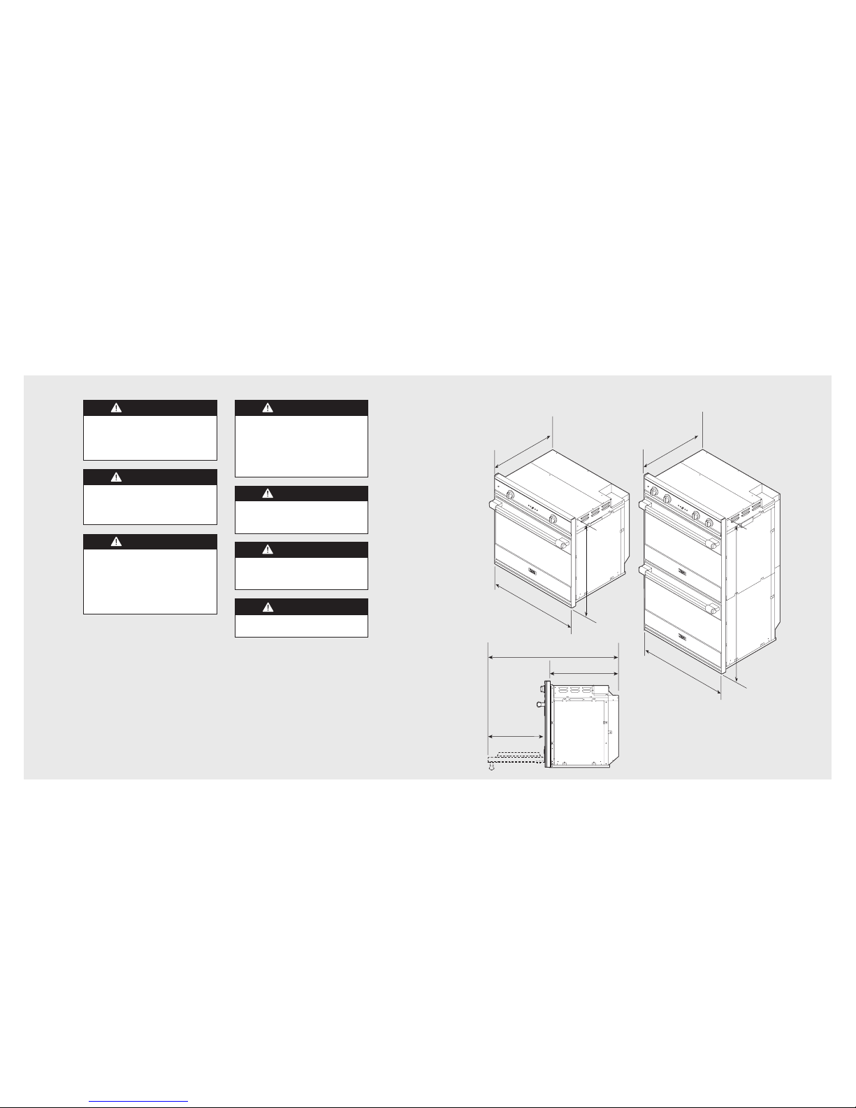
Dimensions
5
IMPORTANT4– Please Read and Follow
WARNING
The misuse of the oven door(s) (e.g.
stepping, sitting, or leaning on them) can
result in hazards or injuries and damage
to the product.
WARNING
ELECTRICAL GROUNDING
INSTRUCTIONS
This oven must be electrically grounded in
accordance with local codes or, in the
absence of local codes, with the National
Electrical Code, ANSI/NFPA-70 – latest
edition.
WARNING
Frame grounded by a 4-conductor cable
assembly. See installation section.
DO NOT USE AN EXTENSION CORD
WITH THIS APPLIANCE. SUCH USE MAY
RESULT IN FIRE, ELECTRICAL SHOCK
OR OTHER PERSONAL INJURY.
WARNING
This appliance should not be used for
space heating. This information is based
on safety considerations.
WARNING
The use of cabinets for storage above the
oven may result in potential fire or burn
hazard.
CAUTION
The oven is heavy—use extreme care
when handling.
51-3/8”
(130.5 cm)
5
1
-
3
/
8
”
(
1
3
0
.
5
c
m)
51-3/8”
(130.5 cm)
25
-3/16”
(64.0 cm)
25-3/16”
(64.0 cm)
29-3/4”
(75.6 cm)
29-3/4”
(75.6 cm)
29-3/8”
(74.6 cm)
23-1/2”
(59.7 cm)
46-3/16”
(117.3 cm)
21-1/4”
(53.9 cm)
30” Single Oven 30” Double Oven
WARNING
DO NOT use the handle or oven door to
lift the oven. Remove door before
installation to ensure that it is not used to
lift the unit. See installation section for
door removal.
Page 4
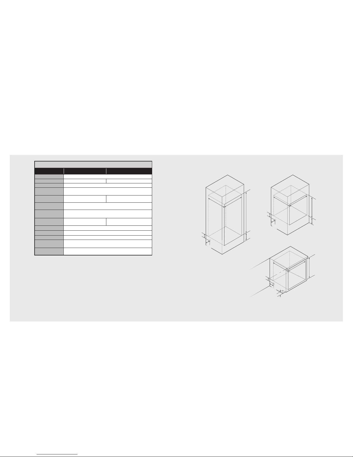
Cutout Dimensions
(For standard installation and flush mount* installations)
7
Specifications
6
30"W. Electric Single/Double
Description
CRDSOE306 CRDDOE306
Overall width
29-3/4” (75.6 cm)
Overall height
29-3/8” (74.6 cm) 51-3/8” (130.5 cm)
Overall depth
To front of door 25-3/16” (64.3 cm)
Cutout width
Standard—28-1/2” (72.4 cm minimum)
Flush mount*—29-5/8” (75.25 cm)
Cutout height
Standard—28-1/4” (71.8 cm)
Flush mount*—29-1/2” (74.9 cm)
Standard—50-5/8” (128.6 cm)
Flush mount*—51-1/2” (130.8 cm)
Cutout depth
Standard—24” (61.0 cm)
Flush mount*—25-1/4” (64.1 cm)
Electrical requirements
4-wire ground, 240 VAC, 30 amp electrical connection for single ovens/
50 amp for double ovens. Unit is equipped with No. 10 ground wire in conduit.
Should be fused separately.
Maximum amp usage
23.3 amps—240 VAC
20.2 amps—208 VAC
46.7 amps—240 VAC
40.5 amps—208 VAC
Oven interior width
25” (63.5 cm)
Oven interior height
16” (40.6 cm)
Oven interior depth
18-1/2” (50.0 cm)
Oven volume
(measured
to AHAM Standard)**
3.8 cu. ft.
Oven volume
(total oven
cavity)
4.3 cu. ft.
*Note: To install the oven in a flush mount application the flush mount accessory kit (D30FTS
for single ovens and D30FTD for double ovens) is required.
**Note: The AHAM Standard for measuring oven capacity subtracts the door plug and
convection baffle dimension from the total oven volume.
28-1/2”
(72.4 cm)
Flush mount
29-5/8”
(75.2 cm)
24”
(61.0 cm)
Flush mount
25-1/4”
(64.1 cm)
28-1/4”
(71.8 cm)
Flush mount
29-1/2”
(74.9 cm)
5” min.
(12.7 cm)
Junction box
location
17”
(43.2 cm)
28-1/2”
(
72.4 cm)
Flush moun
t
29-5/8”
(75.2 cm)
28-1/4”
(
71.8 cm)
Flush mount
29-1/2”
(74.9 cm)
24”
(61.0 cm)
Flush moun
t
25-1/4”
(64.1 cm)
28-1/2”
(72.4 cm)
Flush mount
29-5/8”
(75.2 cm)
50-5/8”
(128.5 cm)
Flush mount
51-1/2”
(130.8 cm)
15-1/4”
(38.7 cm) min.
to floor
4”
(10.2 cm)
5” min.
(12.7 cm)
Junction box
location
4-3/4”
(12.1 cm)
(Floor to bottom
of cutout)
5” min.
(12.7 cm)
Junction box
location
4”
(10.2 cm)
24”
(61.0 cm)
Flush mount
25-1/4”
(64.1 cm)
4”
(10.2 cm)
30” Single Oven Built-In30” Double Oven Built-In
30” Single Oven Undercounter
*Note: To install the oven in a flush mount application the flush mount accessory kit
(D30FTS for single ovens and D30FTD for double ovens) is required.
Page 5
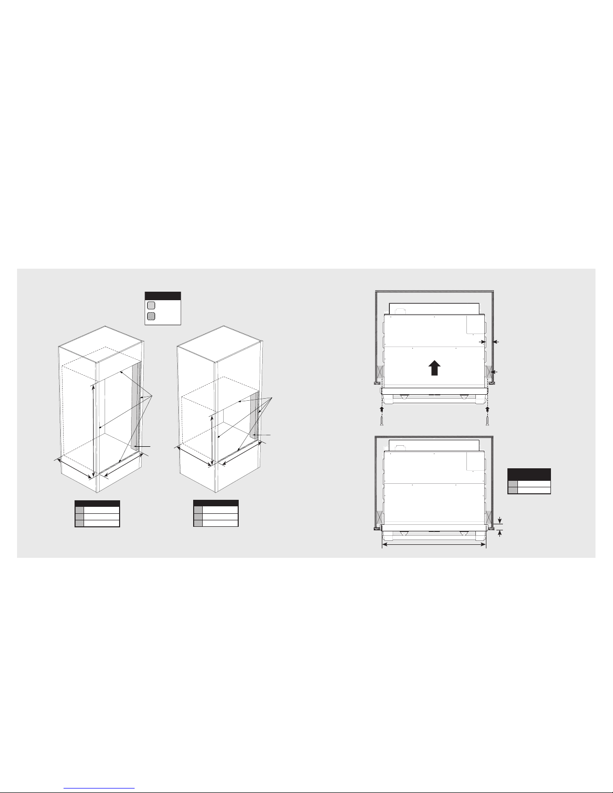
Dimensions (Flush mount installation)
9
Dimensions (Flush mount installation)
8
FLUSH CUTOUT
D 29-5/8” (75.2 cm)
E 25-1/4” (64.1 cm)
F 29-1/2” (74.9 cm)
Finished
Surfaces
Vertical
Blocking
B
A
C
FLUSH CUTOUT
A 29-5/8” (75.2 cm)
B 25-1/4” (64.1 cm)
C 51-1/2” (130.8 cm)
Finished
Surfaces
Vertical
Blocking
E
D
F
LEGEND
Blocking
Finished
Surfaces
ScrewScrew
Vertical
Blocking
Distance will vary
depending on the
cabinet
A
B
Top View
CRITICAL
DIMENSIONS
A 28-1/2” (72.4 cm)
B 1-1/2” (3.8 cm)
*Note: To install the oven in a flush mount application the flush mount accessory kit (D30FTS
for single ovens and D30FTD for double ovens) is required.
Page 6

General Information
• All openings in the wall behind the
appliance or in the floor under the
appliance should be sealed.
• Keep appliance area clear and free from
combustible materials, gasoline and other
flammable vapors.
• Disconnect the electrical supply prior to
servicing or cleaning.
• When removing the appliance for cleaning
or service, disconnect AC power supply
and carefully remove the appliance by
pulling forward.
• Electrical requirements are listed in the
product specifications under the electrical
requirements section.
Recommendations for Unpacking
• Products are shipped on pallets with foam
footings and corrugated inner-packing
and exterior hoods.
• Products are anchored to the pallet using
metal straps that are screwed to the
bottom of the product and the pallet.
• DO NOT remove protective packaging
until you are ready to perform the
installation.
• To remove the packaging, first remove the
staples located at the bottom perimeter
of the corrugated cover.
• Remove the corrugated cover by lifting
it off the product and remove the innerpacking.
• Detach the product from the metal anchor
strip by removing the attachment screw.
• DO NOT remove the protective wrapping
from the product control panel until the
product is installed.
Recommendations for Moving
• Only proper equipment should be used to
move products.
• ALWAYS take steps to protect flooring at
the installation location when moving
products.
11
WARNING
DO NOT use the handle or oven door
to lift the oven. Remove door before
installation to ensure that it is not used to
lift the unit. DO NOT lift or carry the door
by the handle.
CAUTION
The oven is heavy—use extreme care
when handling.
Electrical Requirements
• Oven requires a separate, grounded
4-wire, 240V (AC), 30 amp (single ovens)
and 50 amp (double ovens) service with
its own circuit breaker.
• Wire sizes and connections must conform
with the rating of the appliance and to the
requirements of the National Electrical
Code, ANSI/NFPA-70 – latest edition, or
Canadian Electrical Code, CSA
C22.1-1982 and C22.2 No. 01982 –
latest edition, and all local codes and
ordinances.
• Oven must be connected to the proper
electrical voltage and frequency as
specified on the model/serial rating plate
(located inside the vent ont the right sode
of the oven).
• Oven must be connected to grounded
metal permanent wiring system. Check
with a qualified electrician to make sure
the oven is properly grounded.
• DO NOT ground to a gas pipe.
• DO NOT use an extension cord with this
appliance, because this may result in
electrical shock or other personal injury.
• This unit is equipped with a No. 10
ground wire in the conduit.
• The electrical conduit must be kept to the
top left for a flush installation. NEVER cut
the conduit.
• Connect the flexible armored cable
directly to 4-wire, 240V household service.
If codes permit and separate grounding
wiring is used, we recommend that a
qualified electrician determine the
grounding path and that the wire gauge is
in accordance with local codes.
• Junction boxes installed on rear wall
directly behind oven must be recessed .
• A UL-Listed conduit connector must be
provided at the junction box.
• DO NOT install a fuse in the neutral or
grounding circuit. We recommend a timedelayed fuse or circuit breaker. Connect
directly to the fused disconnect (or circuit
breaker box) through flexible armored, or
non-metallic sheathed, copper cable (with
grounding wire).
10
Page 7
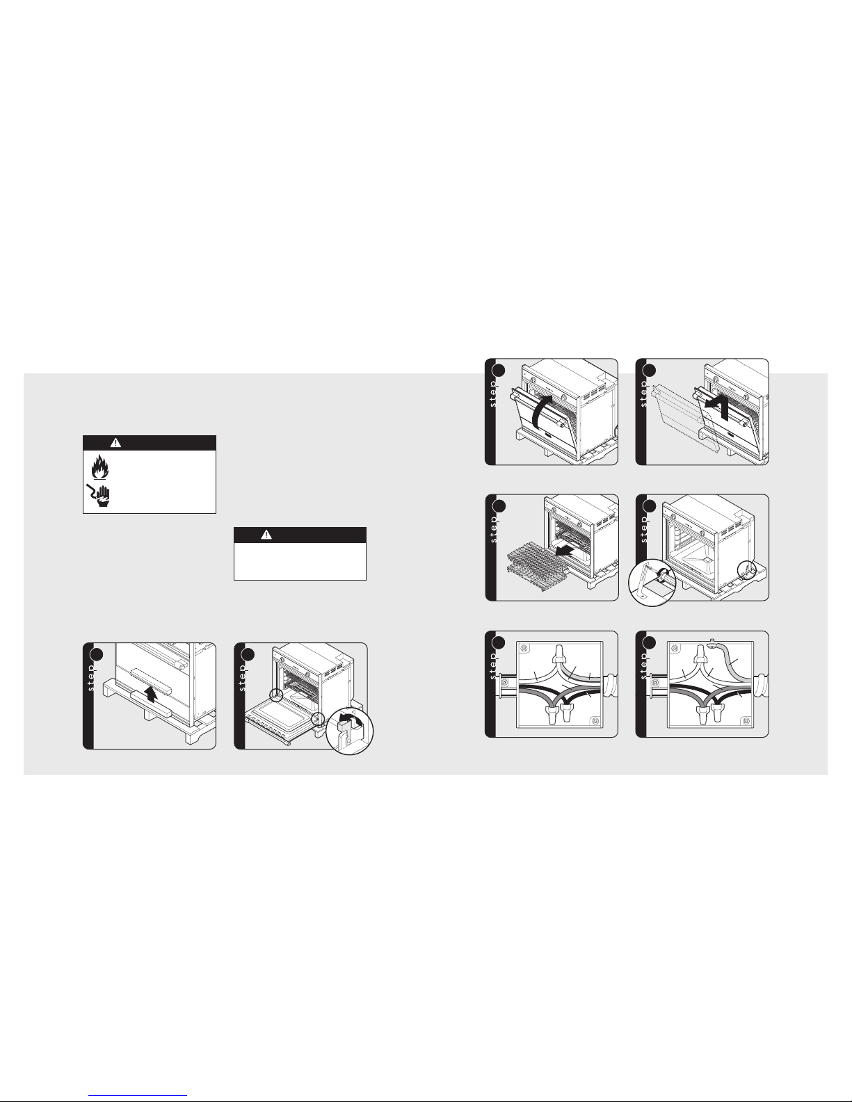
13
3 4
Close the door until it stops.
Push in/lift door up/and then out. Repeat for all doors.
5
6
Remove racks.
Unscrew pallet screws from side of oven.
Neutral
Green
White
Black
Red
7a
Neutral
Green
White
Black
Red
7b
Wiring option 1*
(connect the white and green to the incoming neutral)
Wiring option 2*
(connect the white to the incoming neutral,
attach green to grounded junction box)
Installation (cont.)
*Note: Check local code to see which wiring option should be used when grounding the unit.
12
1
1
2
2
Remove wooden brace on front of pallet.
Open door completely. Rotate door
hinge to unlocked position.
Installation
General Information
Site Preparation
Note: It is recommended that a thorough
site inspection be conducted PRIOR to
unpacking and moving this appliance.
• Confirm available access to adequate
power—
see electrical requirements.
°
Single oven units require a 30 amp circuit
°
Double oven units require a 50 amp circuit
•
Note: A minimum of 2” spacing above
and below the oven to any adjacent items
is required for ventilation purposes.
• It is recommended that 3/4” or thicker
material be utilized to create a support
platform for this appliance.
• BE SURE that support for this appliance is
perpendicular to the front facing of the
wall or cabinet before you perform the
installation.
• Use of a hydraulic lift is recommended for
the installation of double oven units. Be
careful not to bend lower trim/vent.
• All openings in the wall behind the
appliance or in the floor under the
appliance should be sealed.
• Keep appliance area clear and free from
combustible materials, gasoline and other
flammable vapors.
WARNING
DO NOT use the handle or oven door to lift
the oven. Remove door before installation
to ensure that it is not used to lift the unit.
DO NOT lift or carry the door by the handle.
WARNING
FIRE OR ELECTRICAL
SHOCK HAZARD
DO NOT use an extension cord
with this appliance. Such use
may result in fire, electrical shock
or other personal injury.
Page 8
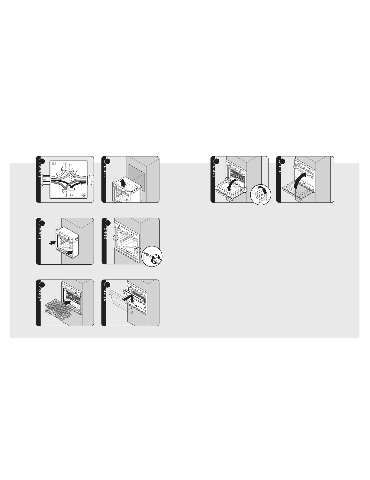
15
1
13
2
14
Open door completely. Rotate door
hinge to locked position.
Close door.
Installation
1. Some stainless steel parts may have a
protective wrap, which must be peeled
off. All stainless steel body parts should
be wiped regularly with hot, soapy water
at the end of each cooling period and
with liquid cleaner designed for this
material when soapy water will not do the
job. If build-up occurs, DO NOT use steel
wool, or abrasive cloths, cleaners, or
powders. If it is necessary to scrape
stainless steel surface to remove
encrusted material, soak area with hot,
wet towels to loosen the material, then
use a wooden or nylon spatula or scraper.
DO NOT use a metal knife, spatula, or
any other metal tool to scrape stainless
steel surfaces. Scratches are almost
impossible to remove.
2. The interior of the oven should be washed
thoroughly with hot, soapy water to
remove film residues and installation
debris before being used for food
preparation, then rinsed and wiped dry.
Solutions stronger than soapy water are
rarely needed.
Final Preparation
14
Neutral
Green
White
Black
Red
7c 8
Wiring option 3*
(connect the white to the incoming neutral,
attach green to suitable ground)
Lift oven into position.
9
10
Push oven straight in.
Attach screws to the side of the framing.
Note: Two screws for single ovens, four screws
for double ovens (screws not included).
11 12
Replace racks.
Replace door.
Installation (cont.)
*Note: Check local code to see which wiring option should be used when grounding the unit.
Page 9
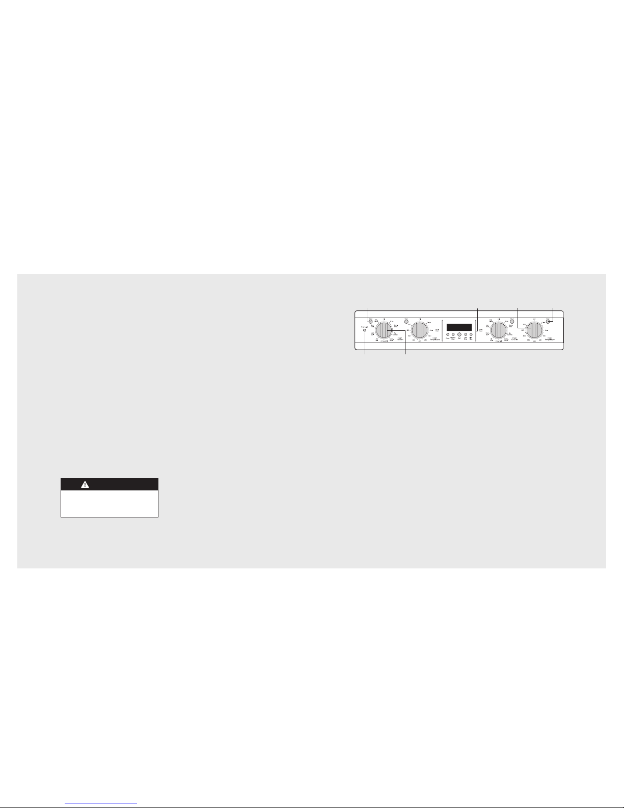
Performance Checklist (cont.)
17
Performance Checklist
A qualified installer should carry out the
following checks:
h Check oven Bake Function—bake element
on full power, center and outside broil
elements at partial power. Convection
Bake function—bake and broil elements
the same with the convection fan “ON”.
h Check TruConvec™ function—TruConvec
element (behind convection fan cover)
“ON” and convection fan “ON”.
h Check High Broil function—both broil
elements at full power. Convection broil
function is the same with convection fan
“ON”.
h Check Medium Broil function—inner and
outer broil elements pulse on and off.
h Check Low Broil function—inner broil
element only.
h Check Self-Clean function—Door will lock
in approximately 30 seconds, the center
and outside broil elements will turn “ON”
and the bake element will tur n “ON” at
partial power. Check broil elements
through window to make sure they are
“ON”, then abort self-clean cycle to
unlock door.
Any adjustments necessary that are a result of
the installer not following instructions will be
the responsibility of the installer, dealer, or the
end user of the product.
16
CAUTION
DO NOT run self-clean cycle check for
more than 10 minutes with the oven racks
and rack supports inside oven to avoid
discoloration due to the high temperature.
Electronic
Timing Center
Off/On
Indicator Light
Interior
Oven Li
g
ht Control
Temperature
Control
Self-Clean
Indicator Light
Oven Function Selector
Page 10

19
Notes
________________________________________________________________________________________________________________________________________________________
________________________________________________________________________________________________________________________________________________________
________________________________________________________________________________________________________________________________________________________
________________________________________________________________________________________________________________________________________________________
________________________________________________________________________________________________________________________________________________________
________________________________________________________________________________________________________________________________________________________
________________________________________________________________________________________________________________________________________________________
________________________________________________________________________________________________________________________________________________________
________________________________________________________________________________________________________________________________________________________
________________________________________________________________________________________________________________________________________________________
________________________________________________________________________________________________________________________________________________________
________________________________________________________________________________________________________________________________________________________
________________________________________________________________________________________________________________________________________________________
________________________________________________________________________________________________________________________________________________________
________________________________________________________________________________________________________________________________________________________
________________________________________________________________________________________________________________________________________________________
________________________________________________________________________________________________________________________________________________________
________________________________________________________________________________________________________________________________________________________
________________________________________________________________________________________________________________________________________________________
________________________________________________________________________________________________________________________________________________________
________________________________________________________________________________________________________________________________________________________
________________________________________________________________________________________________________________________________________________________
18
Service Information
If service is required, call your dealer or authorized service agency. The name of the authorized
service agency can be obtained from the dealer or distributor in your area.
Have the following information readily available.
• Model number
• Serial number
• Date purchased
• Name of dealer from whom purchased
Clearly describe the problem that you are having. If you are unable to obtain the name of an
authorized service agency, or if you continue to have service problems, contact Viking Range
Corporation at 1-888-845-4641 , or write to:
VIKING RANGE CORPORATION
PREFERRED SERVICE
1803 Hwy 82W
Greenwood, Mississippi 38930 USA
Record the information indicated below. You will need it if service is ever
required. The model and serial number for your oven can be found by
opening the door and looking under neath the control panel on the left
hand side.
Model no. _ _ _ _ _ _ _ _ _ _ _ _ _ _ _ _ _ _ _ _ _ _ _ _ _ _ _ _ _Serial no. _ _ _ _ _ _ _ _ _ _ _ _ _ _ _ _ _ _ _ _ _ _ _ _ _ _ _ _ _ _ _ _
Date of purchase _ _ _ _ _ _ _ _ _ _ _ _ _ _ _ _ _ _ _Date installed _ _ _ _ _ _ _ _ _ _ _ _ _ _ _ _ _ _ _ _ _ _ _ _ _ _ _ _ _ _ _ _
Dealer’s name _ _ _ _ _ _ _ _ _ _ _ _ _ _ _ _ _ _ _ _ _ _ _ _ _ _ _ _ _ _ _ _ _ _ _ _ _ _ _ _ _ _ _ _ _ _ _ _ _ _ _ _ _ _ _ _ _ _ _ _ _ _ _ _ _ _ _
Address _ _ _ _ _ _ _ _ _ _ _ _ _ _ _ _ _ _ _ _ _ _ _ _ _ _ _ _ _ _ _ _ _ _ _ _ _ _ _ _ _ _ _ _ _ _ _ _ _ _ _ _ _ _ _ _ _ _ _ _ _ _ _ _ _ _ _ _ _ _ _ _
_ _ _ _ _ _ _ _ _ _ _ _ _ _ _ _ _ _ _ _ _ _ _ _ _ _ _ _ _ _ _ _ _ _ _ _ _ _ _ _ _ _ _ _ _ _ _ _ _ _ _ _ _ _ _ _ _ _ _ _ _ _ _ _ _ _ _ _ _ _ _ _ _ _ _ _ _ _ _ _
If service requires installation of parts, use only authorized parts to insure protection
under the warranty.
Keep this manual for future reference.
 Loading...