

Page 1
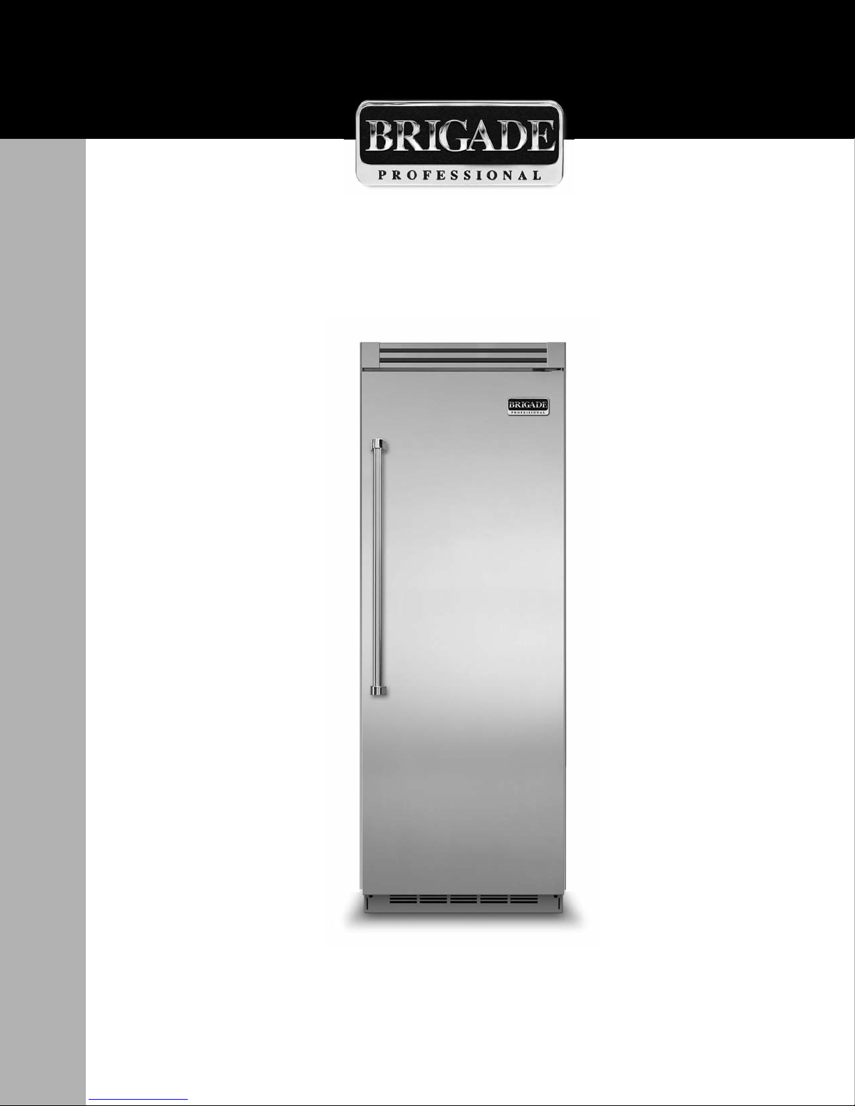
Installation Guide
All Refrigerator/All Freezer
Page 2

2
Table of Contents
Warnings & Important Information
_ _ _ _ _ _ _ _ _ _ _ _ _ _ _ _ _ _ _ _ _ _ _ _ _ _ _ _ _ _ _ _ _ _ _ _ _ _ _ _ _ _ _ _ _ _ _ _ _ _ _ _ _ _ _ _ _
3
Professional
D i m e n s i o n s & S p e c i f i c a t i o n s ( 3 0 ” & 3 6 ” ) _ _ _ _ _ _ _ _ _ _ _ _ _ _ _ _ _ _ _ _ _ _ _ _ _ _ _ _ _ _ _ _ _ _ _ _ _ _ _ _ _ _ _ 6
D i m e n s i o n s & S p e c i f i c a t i o n s ( 3 0 ” & 3 6 ” w i t h f l u s h m o u n t t r i m ) _ _ _ _ _ _ _ _ _ _ _ _ _ _ _ _ _ _ _ _ _ _ _ 8
C u t o u t D i m e n s i o n s ( 3 0 ” ) _ _ _ _ _ _ _ _ _ _ _ _ _ _ _ _ _ _ _ _ _ _ _ _ _ _ _ _ _ _ _ _ _ _ _ _ _ _ _ _ _ _ _ _ _ _ _ _ _ _ _ _ _ _ _ _ 1 0
A n t i - T i p D i m e n s i o n s ( 3 0 ” ) _ _ _ _ _ _ _ _ _ _ _ _ _ _ _ _ _ _ _ _ _ _ _ _ _ _ _ _ _ _ _ _ _ _ _ _ _ _ _ _ _ _ _ _ _ _ _ _ _ _ _ _ _ _ _ 1 1
C u t o u t D i m e n s i o n s ( 3 6 ” ) _ _ _ _ _ _ _ _ _ _ _ _ _ _ _ _ _ _ _ _ _ _ _ _ _ _ _ _ _ _ _ _ _ _ _ _ _ _ _ _ _ _ _ _ _ _ _ _ _ _ _ _ _ _ _ _ 1 2
A n t i - T i p D i m e n s i o n s ( 3 6 ” ) _ _ _ _ _ _ _ _ _ _ _ _ _ _ _ _ _ _ _ _ _ _ _ _ _ _ _ _ _ _ _ _ _ _ _ _ _ _ _ _ _ _ _ _ _ _ _ _ _ _ _ _ _ _ _ 1 3
D i m e n s i o n s & S p e c i f i c a t i o n s ( D u a l 3 0 ” / D u a l 3 0 ” & 3 6 ” ) _ _ _ _ _ _ _ _ _ _ _ _ _ _ _ _ _ _ _ _ _ _ _ _ _ _ _ _ 1 4
Dimensions & Specifications (Dual 30”/ Dual 30” & 36” with flush mount trim) _ _ _ _ _ _ _ _ _ 18
C u t o u t D i m e n s i o n s ( D u a l 3 0 ” ) _ _ _ _ _ _ _ _ _ _ _ _ _ _ _ _ _ _ _ _ _ _ _ _ _ _ _ _ _ _ _ _ _ _ _ _ _ _ _ _ _ _ _ _ _ _ _ _ _ _ _ _ 2 2
A n t i - T i p D i m e n s i o n s ( D u a l 3 0 ” ) _ _ _ _ _ _ _ _ _ _ _ _ _ _ _ _ _ _ _ _ _ _ _ _ _ _ _ _ _ _ _ _ _ _ _ _ _ _ _ _ _ _ _ _ _ _ _ _ _ _ _ 2 3
C u t o u t D i m e n s i o n s ( D u a l 3 0 ” & 3 6 ” ) _ _ _ _ _ _ _ _ _ _ _ _ _ _ _ _ _ _ _ _ _ _ _ _ _ _ _ _ _ _ _ _ _ _ _ _ _ _ _ _ _ _ _ _ _ _ 2 4
A n t i - T i p D i m e n s i o n s ( D u a l 3 0 ” & 3 6 ” ) _ _ _ _ _ _ _ _ _ _ _ _ _ _ _ _ _ _ _ _ _ _ _ _ _ _ _ _ _ _ _ _ _ _ _ _ _ _ _ _ _ _ _ _ _ 2 5
C u t o u t D i m e n s i o n s ( D u a l 3 6 ” ) _ _ _ _ _ _ _ _ _ _ _ _ _ _ _ _ _ _ _ _ _ _ _ _ _ _ _ _ _ _ _ _ _ _ _ _ _ _ _ _ _ _ _ _ _ _ _ _ _ _ _ _ 2 6
A n t i - T i p D i m e n s i o n s ( D u a l 3 6 ” ) _ _ _ _ _ _ _ _ _ _ _ _ _ _ _ _ _ _ _ _ _ _ _ _ _ _ _ _ _ _ _ _ _ _ _ _ _ _ _ _ _ _ _ _ _ _ _ _ _ _ _ 2 7
Cabinet Information _ _ _ _ _ _ _ _ _ _ _ _ _ _ _ _ _ _ _ _ _ _ _ _ _ _ _ _ _ _ _ _ _ _ _ _ _ _ _ _ _ _ _ _ _ _ _ _ _ _ _ _ _ _ _ _ _ _ _ _ 2 8
Cabinet Information (with flush mount trim) _ _ _ _ _ _ _ _ _ _ _ _ _ _ _ _ _ _ _ _ _ _ _ _ _ _ _ _ _ _ _ _ _ _ _ _ _ _ _ _ 30
Custom Side Panel Dimensions _ _ _ _ _ _ _ _ _ _ _ _ _ _ _ _ _ _ _ _ _ _ _ _ _ _ _ _ _ _ _ _ _ _ _ _ _ _ _ _ _ _ _ _ _ _ _ _ _ _ _ _ _ _ 3 2
Custom Side Panel Dimensions (with flush mount trim) _ _ _ _ _ _ _ _ _ _ _ _ _ _ _ _ _ _ _ _ _ _ _ _ _ _ _ _ _ _ _ _ _ _ 33
General Information _ _ _ _ _ _ _ _ _ _ _ _ _ _ _ _ _ _ _ _ _ _ _ _ _ _ _ _ _ _ _ _ _ _ _ _ _ _ _ _ _ _ _ _ _ _ _ _ _ _ _ _ _ _ _ _ _ _ _ _ _ _ _ _ 3 4
U n p a c k i n g & M o v i n g _ _ _ _ _ _ _ _ _ _ _ _ _ _ _ _ _ _ _ _ _ _ _ _ _ _ _ _ _ _ _ _ _ _ _ _ _ _ _ _ _ _ _ _ _ _ _ _ _ _ _ _ _ _ _ _ _ _ _ _ 3 6
F l u s h M o u n t S i d e Tr i m I n s t a l l a t i o n _ _ _ _ _ _ _ _ _ _ _ _ _ _ _ _ _ _ _ _ _ _ _ _ _ _ _ _ _ _ _ _ _ _ _ _ _ _ _ _ _ _ _ _ _ _ _ _ _ _ _ _ 3 7
I n s t a l l a t i o n _ _ _ _ _ _ _ _ _ _ _ _ _ _ _ _ _ _ _ _ _ _ _ _ _ _ _ _ _ _ _ _ _ _ _ _ _ _ _ _ _ _ _ _ _ _ _ _ _ _ _ _ _ _ _ _ _ _ _ _ _ _ _ _ _ _ _ _ _ _ _ _ _ 3 7
H i n g e A d j u s t m e n t _ _ _ _ _ _ _ _ _ _ _ _ _ _ _ _ _ _ _ _ _ _ _ _ _ _ _ _ _ _ _ _ _ _ _ _ _ _ _ _ _ _ _ _ _ _ _ _ _ _ _ _ _ _ _ _ _ _ _ _ _ _ 3 8
K i c k p l a t e I n s t a l l a t i o n _ _ _ _ _ _ _ _ _ _ _ _ _ _ _ _ _ _ _ _ _ _ _ _ _ _ _ _ _ _ _ _ _ _ _ _ _ _ _ _ _ _ _ _ _ _ _ _ _ _ _ _ _ _ _ _ _ _ _ _ 4 0
Door Stop Adjustment _ _ _ _ _ _ _ _ _ _ _ _ _ _ _ _ _ _ _ _ _ _ _ _ _ _ _ _ _ _ _ _ _ _ _ _ _ _ _ _ _ _ _ _ _ _ _ _ _ _ _ _ _ _ _ _ _ _ 4 1
F i n a l I n s t a l l a t i o n _ _ _ _ _ _ _ _ _ _ _ _ _ _ _ _ _ _ _ _ _ _ _ _ _ _ _ _ _ _ _ _ _ _ _ _ _ _ _ _ _ _ _ _ _ _ _ _ _ _ _ _ _ _ _ _ _ _ _ _ _ _ _ _ 4 1
Performance Checklist _ _ _ _ _ _ _ _ _ _ _ _ _ _ _ _ _ _ _ _ _ _ _ _ _ _ _ _ _ _ _ _ _ _ _ _ _ _ _ _ _ _ _ _ _ _ _ _ _ _ _ _ _ _ _ _ _ _ _ _ _ _ 4 3
C o n t r o l P a n e l s _ _ _ _ _ _ _ _ _ _ _ _ _ _ _ _ _ _ _ _ _ _ _ _ _ _ _ _ _ _ _ _ _ _ _ _ _ _ _ _ _ _ _ _ _ _ _ _ _ _ _ _ _ _ _ _ _ _ _ _ _ _ _ _ _ _ _ _ _ 4 4
Service & Registration_ _ _ _ _ _ _ _ _ _ _ _ _ _ _ _ _ _ _ _ _ _ _ _ _ _ _ _ _ _ _ _ _ _ _ _ _ _ _ _ _ _ _ _ _ _ _ _ _ _ _ _ _ _ _ _ _ _ _ _ _ _ _ 4 5
Page 3
3
IMPORTANT–Please Read and Follow!
• Make sure that incoming voltage is the same
as unit rating. An electric rating plate
specifying voltage, frequency, wattage,
amperage, and phase is attached to the
product.
• To reduce the risk of fire, electric shock, or
injury to persons, installation work and
electrical wiring must be done by qualified
people in accordance with all applicable
codes and standards, including fire-rated
construction.
• The installer should leave these instructions
with the consumer who should retain them
for local inspector’s use and for future
reference.
Your safety and the safety of others is very
important.
We have provided many important safety
messages in this manual and on your
appliance. Always read and obey all
safety messages.
This is the safety alert symbol. This
symbol alerts you to hazards that
can kill or hurt you and others.
All safety messages will be preceded by the
safety alert symbol and the word“DANGER”
or “WARNING.”These words mean:
DANGER
You will be killed or seriously injured if
you don’t follow instructions.
WARNING
You can be killed or seriously injured if
you don’t follow instructions.
All safety messages will identify the
hazard, tell you how to reduce the chance
of injury, and tell you what can happen if
the instructions are not followed.
Page 4

IMPORTANT–Please Read and Follow!
4
A GFI
shall be used if required by NFPA-70 (National Electric Code), federal/state/local laws, or
local ordinances.
• The required use of a GFI is normally related to the location of a receptacle with respect to
any significant sources of water or moisture.
• Viking Range, LLC will NOT warranty any problems resulting from GFI outlets which are not
installed properly or do not meet the requirements below.
If the use of a GFI is required
, it should be:
• Of the receptacle type (breaker type or portable type NOT recommended)
• Used with permanent wiring only (temporary or portable wiring NOT recommended)
• On a dedicated circuit (no other receptacles, switches or loads in the circuit)
• Connected to a standard breaker of appropriate size (GFI breaker of the same size NOT
recommended)
• Rated for Class A (5 mA +/- 1 mA trip current) as per UL 943 standard)
• In good condition and free from any loose-fitting gaskets (if applicable in outdoor situations)
• Protected from moisture (water, steam, high humidity) as much as reasonably possible
Page 5
IMPORTANT–Please Read and Follow!
5
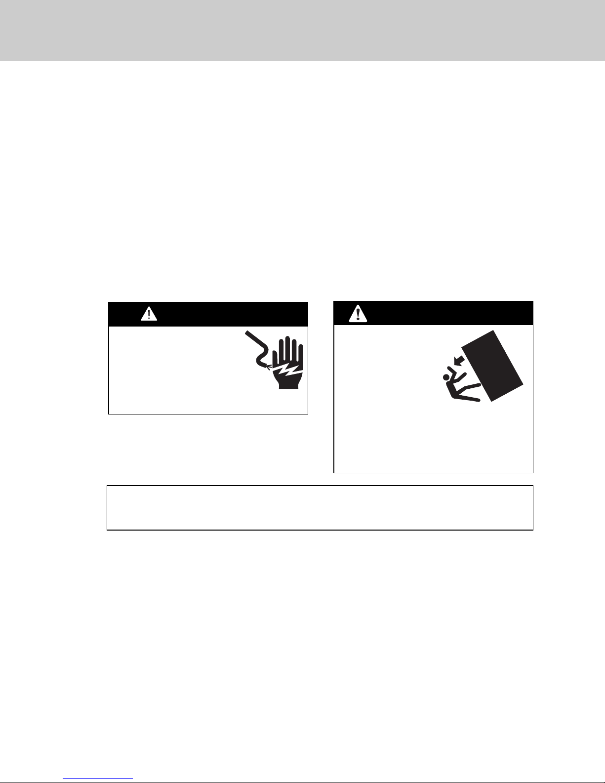
WARNING
ELECTRICAL SHOCK
HAZARD
Disconnect power or turn
power disconnect switch to
OFF position before removing
top grille. Failure to do so can
result in death or electrical shock.
WARNING
TIP OVER HAZARD
Appliance is top
heavy and tips easily
when not completely
installed. Keep doors
closed until appliance
is completely installed
and secured per installation instructions.
Use two or more people to move and
install appliance. Failure to do so can
result in death or serious injury.
Most of the unit’s weight is at the top. Extra care is needed when moving the unit to prevent
tipping. Use cardboard shipping material or plywood under unit until it is installed in the
operating position to protect floor surface.
It is your responsibility to:
• comply with installation specifications and dimensions.
• properly install unit.
• remove any moldings or decorative panels that prevent the unit from being serviced.
• make sure that you have these materials (not provided with your unit), which are necessary
for proper installation:
• 1/4” (6 mm) copper tubing with shutoff valve
• 6– #8 x 3” (7.6 cm) wood screws (longer screws may be required)
• 1– Saddle valve (do not use self-piercing feature of the valve)
• assure that floor will support unit, door panels and contents (approximately 1200 pounds [540 kg]).
• provide a properly grounded electrical outlet.
• assure that location will permit appliance doors to open 90° minimum.
Page 6
36”
(
91.
5 cm)
3–19/32”
30”
(76.2 cm)
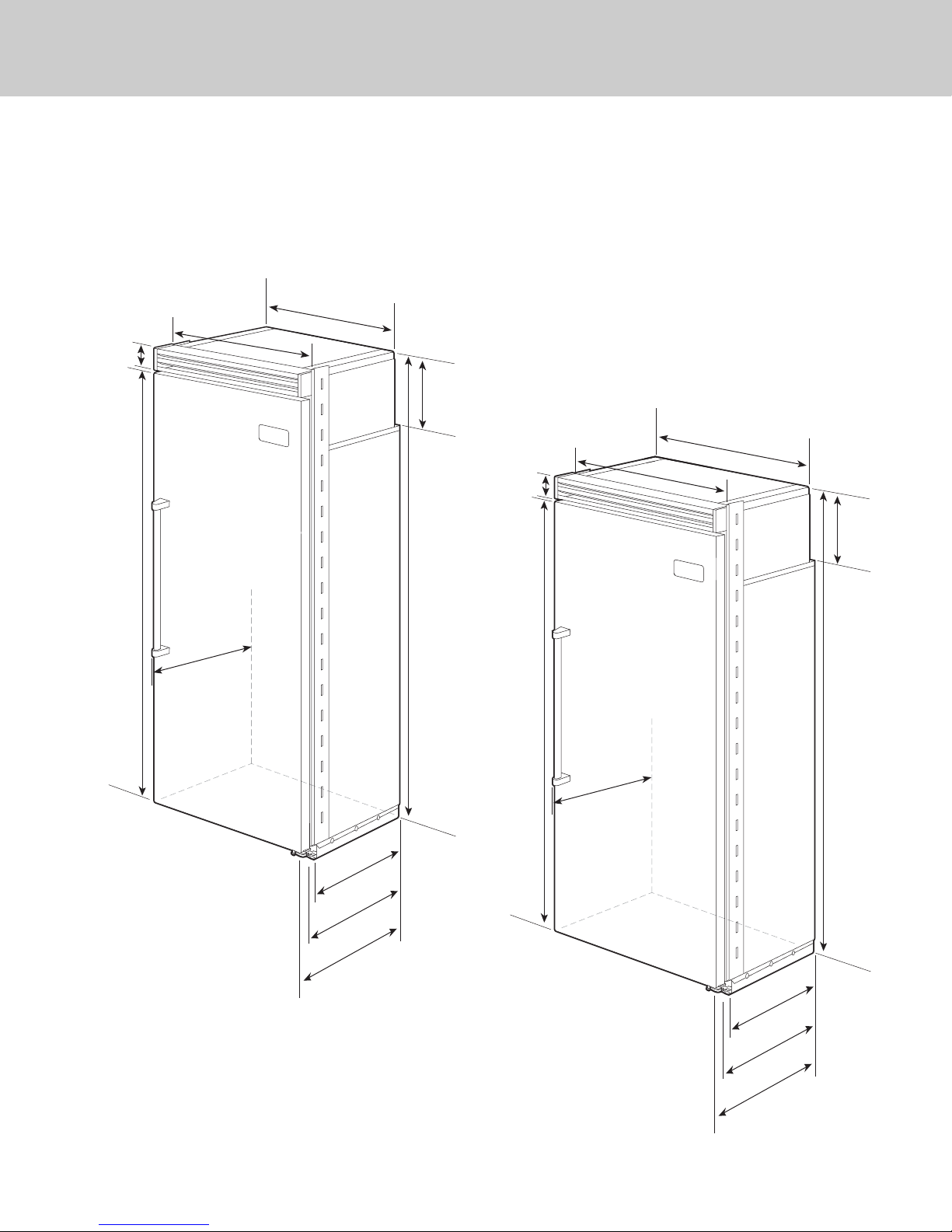
Dimensions
6
30” All Refrigerator/All Freezer
36” All Refrigerator/All Freezer
(9.1 cm)
29”
30”
30”
(76.2 cm)
(76.2 cm)
(73.7 cm)
75–15/16”
(192.9 cm
)
26-1/2”
(67.3 cm)
9–5/32”
(23.3 cm)
82–3/4”
(210.2 cm)
min.
to
84–1/16”
(213.5 cm)
max.
3–19/32”
(9.1 cm)
)
75–15/16”
(192.9 cm)
35”
(88.9 cm)
36”
36”
(91.5 cm)
(91.5 cm)
82–3/4”
(210.2 cm)
26-1/2”
(67.3 cm)
84–1/16”
(213.5 cm)
9–5/32”
(23.3 cm)
min.
to
max.
0–3/4
2
(52.7 cm)
22–3/16”
(56.4 cm)
24”
(61.0 cm)
”
”
4
0–3/
2
(52.7 cm)
22–3/16”
(56.4 cm)
24”
(61.0 cm)
Page 7
7
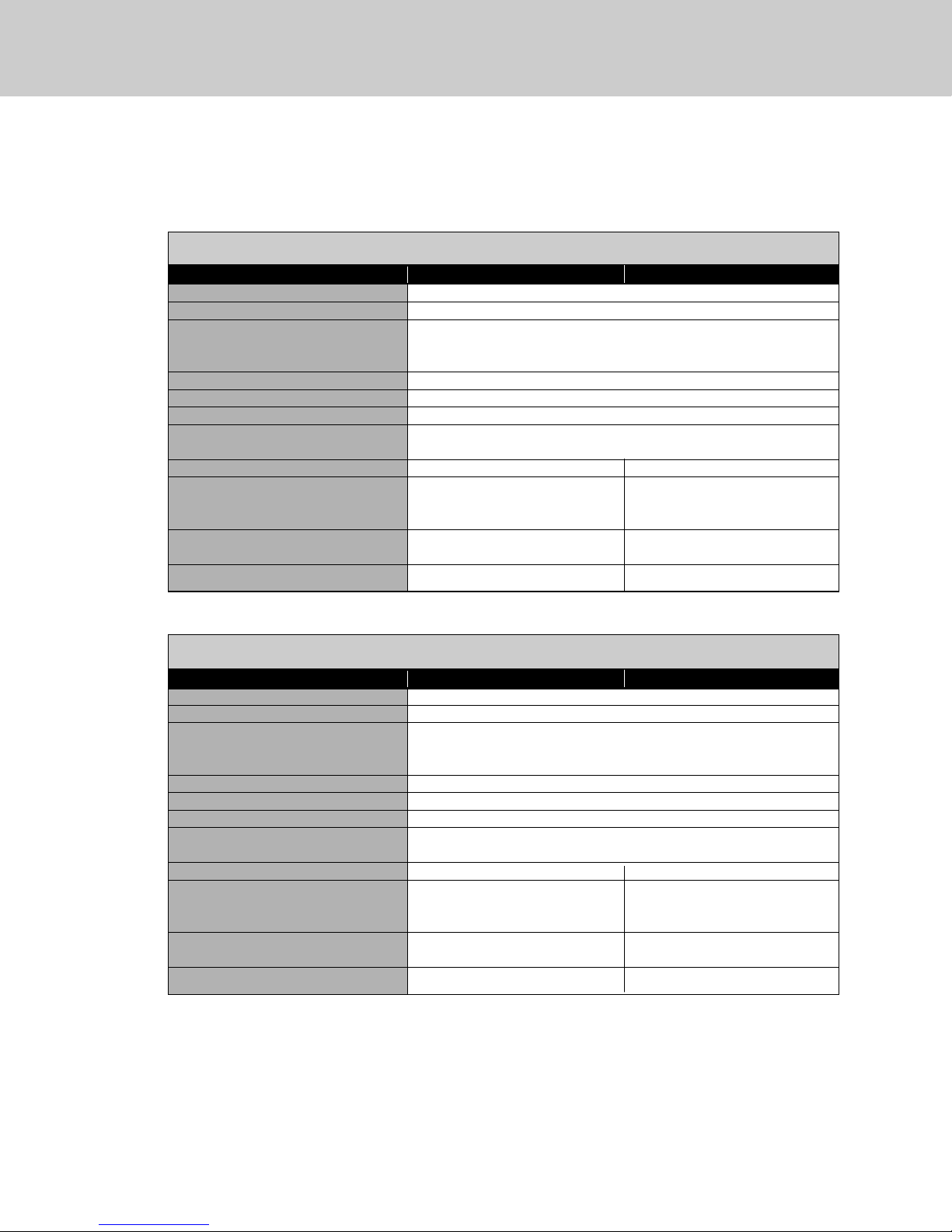
Specifications
30” All Refrigerator/All Freezer
Description CVCFB CVCRB
Overall width 30” (76.2 cm)
Overall height from bottom 82-3/4” (210.2 cm) min. to 84-1/16” (213.5 cm) max.
Overall depth from rear To front edge of side trim: 22-3/16” (56.4 cm)
To front of top grille: 24” (61.0 cm)
To front of handle endcap: 26-1/2” (67.3 cm)
Cutout width 29-5/8” (75.2 cm) min. to 29-3/4” (75.6 cm) max.
Cutout height 82-7/8” (210.5 cm) min. to 84-1/16” (213.5 cm) max.
Cutout depth 24” (61.0 cm) min.
Electrical requirements 115 volt, 60 Hz, 15 amp dedicated circuit; 3-wire cord with
grounded 3-prong plug attached to product
Maximum amp usage 9.1 amps 5.7 amps
Inlet water requirements 1/4” copper tubing inlet
waterline; minimum 20 psi; N/A
maximum 120 psi
Overall interior dimensions
Total capacity 15.9 cu. ft. (450 liters) 18.4 cu. ft. (522 liters)
Approximate shipping weight 550 lbs. (247.5 kg) 525 lbs. (236.3 kg)
36” All Refrigerator/All Freezer
Description CVCFB CVCRB
Overall width 36” (91.5 cm)
Overall height from bottom 82-3/4” (210.2 cm) min. to 84-1/16” (213.5 cm) max.
Overall depth from rear To front edge of side trim: 22-3/16” (56.4 cm)
To front of top grille: 24” (61.0 cm)
To front of handle endcap: 26-1/2” (67.3 cm)
Cutout width 35-5/8” (90.5 cm) min. to 35-3/4” (90.8 cm) max.
Cutout height 82-7/8” (210.5 cm) min. to 84-1/16” (213.5 cm) max.
Cutout depth 24” (61.0 cm) min.
Electrical requirements 115 volt, 60 Hz, 15 amp dedicated circuit; 3-wire cord with
grounded 3-prong plug attached to product
Maximum amp usage 9.5 amps 6.5 amps
Inlet water requirements 1/4” copper tubing inlet
waterline; minimum 20 psi; N/A
maximum 120 psi
Overall interior dimensions
Total capacity 19.2 cu. ft. (544 liters) 22.8 cu. ft. (646 liters)
Approximate shipping weight 605 lbs. (272.3 kg) 590 lbs. (265.5 kg)
Page 8
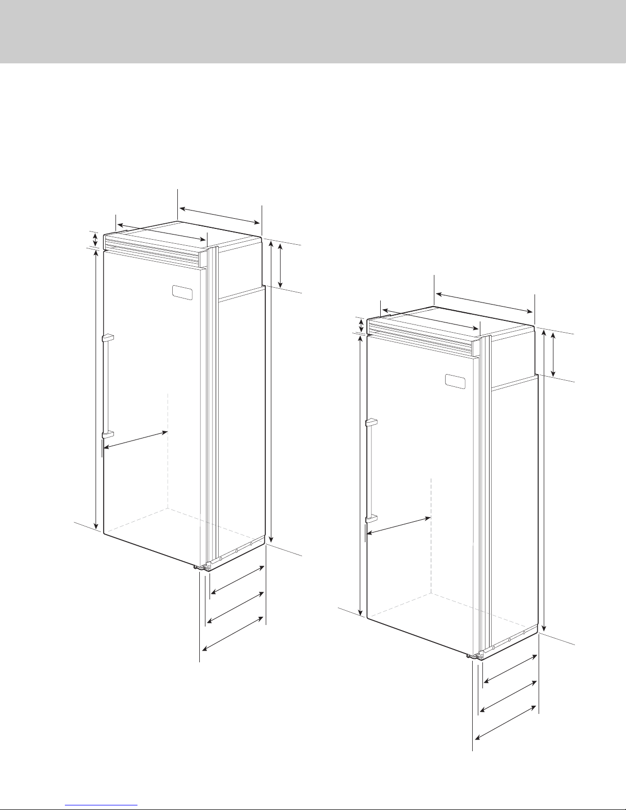
36”
(91.5 cm)
3–19/32”
30”
(76.2 cm)
Dimensions
8
30” All Refrigerator/All Freezer
with Flush Mount Trim
36” All Refrigerator/All Freezer
with Flush Mount Trim
Note: Flush Mount Trim (PBIRFTKSS) purchased separately.
(9.1 cm)
29”
30”
30”
(76.2 cm)
(76.2 cm)
(73.7 cm)
75–15/16”
(192.9 cm
)
26–1/2”
(67.3 cm)
9–5/32”
(23.3 cm)
82–3/4”
(210.2 cm)
min.
to
84–1/16”
(213.5 cm)
max.
3–19/32”
(9.1 cm)
75–15/16”
(192.9 cm)
35”
(88.9 cm)
36”
36”
(91.5 cm)
(91.5 cm)
26–1/2”
(67.3 cm)
9–5/32”
(23.3 cm)
82–3/4”
(210.2 cm)
min.
to
84–1/16”
(213.5 cm)
max.
0–3/4
2
(52.7 cm)
23–3/8”
(59.4 cm)
24”
(61.0 cm)
”
”
0–3/4
2
(52.7 cm)
23–3/8”
(59.4 cm)
24”
(61.0 cm)
Page 9
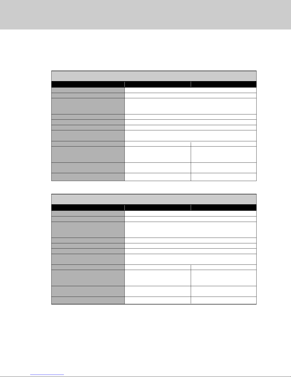
Specifications
9
30” All Refrigerator/All Freezer with Flush Mount Trim
Description CVCFB/Flush Mount CVCRB/Flush Mount
Overall width 30” (76.2 cm)
Overall height from bottom 82-3/4” (210.2 cm) min. to 84-1/16” (213.5 cm) max.
Overall depth from rear To front edge of side trim: 23-3/8” (59.4 cm)
To front of top grille: 24” (61.0 cm)
To front of handle endcap: 26-1/2” (67.3 cm)
Cutout width 30” (74.9 cm)
Cutout height 82-7/8” (210.5 cm) min. to 84-1/16” (213.5 cm) max.
Cutout depth 24” (61.0 cm) min.
Electrical requirements 115 volt, 60 Hz, 15 amp dedicated circuit; 3-wire cord with
grounded 3-prong plug attached to product
Maximum amp usage 9.1 amps 5.7 amps
Inlet water requirements 1/4” copper tubing inlet
waterline; minimum 20 psi; N/A
maximum 120 psi
Overall interior dimensions
Total capacity 15.9 cu. ft. (450 liters) 18.4 cu. ft. (522 liters)
Approximate shipping weight 550 lbs. (247.5 kg) 525 lbs. (236.3 kg)
36” All Refrigerator/All Freezer with Flush Mount Trim
Description CVCFB/Flush Mount CVCRB/Flush Mount
Overall width 36” (91.5 cm)
Overall height from bottom 82-3/4” (210.2 cm) min. to 84-1/16” (213.5 cm) max.
Overall depth from rear To front edge of side trim: 23-3/8” (59.4 cm)
To front of top grille: 24” (61.0 cm)
To front of handle endcap: 26-1/2” (67.3 cm)
Cutout width 36” (91.4 cm)
Cutout height 82-7/8” (210.5 cm) min. to 84-1/16” (213.5 cm) max.
Cutout depth 24” (61.0 cm) min.
Electrical requirements 115 volt, 60 Hz, 15 amp dedicated circuit; 3-wire cord with
grounded 3-prong plug attached to product
Maximum amp usage 9.5 amps 6.5 amps
Inlet water requirements 1/4” copper tubing inlet
waterline; minimum 20 psi; N/A
maximum 120 psi
Overall interior dimensions
Total capacity 19.2 cu. ft. (544 liters) 22.8 cu. ft. (646 liters)
Approximate shipping weight 605 lbs. (272.3 kg) 590 lbs. (265.5 kg)
Page 10
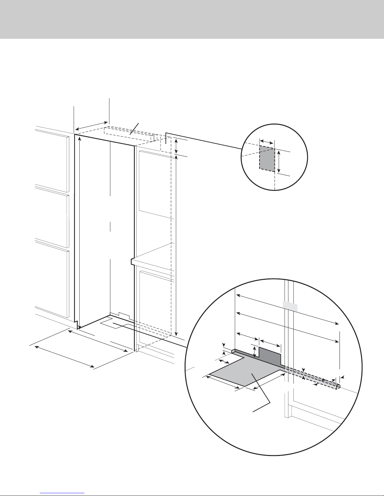
Cutout Dimensions
10
30” All Refrigerator/All Freezer
24”
(61.0 cm)
82–7/8”
(210.5 cm) min.
anti-tip board &
opening height
84–1/16”
(213.5 cm) max.
anti-tip board &
opening height
See Anti-Tip board installation
(22.9 cm)
73–3/8”
(186.4 cm)
9”
Electric Outlet Location
6”
(15.2 cm)
9”
(22.9 cm)
Water Line Entry Area
Note: Shown for All Freezer Only
30”
(76.2 cm)
Flush Mount only
29–5/8”
(75.2 cm) min.
to
29-3/4”
(75.6 cm) max.
(76.
3
0”
2 cm)
Flush Mount only
3–5/8”
(9.2 cm)
(27.3 cm)
5/8”
(1.5 cm)
10–3/4”
water line entry
29–5/8”
7–5/8”
(75.2 cm)
(19.4 cm)
3”
(7.6 cm)
6–3/4”
(17.1 cm)
Optional floor
10–1/2”
(26.7 cm)
5/8”
(1.5 cm)
5/8”
(1.5 cm)
1”
(2.5 cm)
Page 11
Bottom of anti-tip board is 3–7/8” (9.8 cm) below opening height.
Note: Top of unit must be placed firmly under anti-tip board.
Anti-Tip Location
Flush Mount Anti-Tip Location
NOTE: If unit is installed deeper than
24” (61.0 cm),then shim behind the mounting
board by the difference.
NOTE: If unit is installed deeper than
24” (61.0 cm), then shim behind the mounting
board by the difference.
Two 2”x 4” mounting boards
3” (7.6 cm) x 3-1/2” (8.9 cm)
One 2”x 4” mounting board
1–1/2” (3.8 cm) x 3-1/2” (8.9 cm)
79–3/8”
(201.6 cm) min.
to bottom of
anti-tip board
80–1/2”
(204.6 cm) max.
to bottom of
anti-tip board
23”
(58.4 cm)
3–1/2”
(8.9 cm)
3”
(7.6 cm)
23”
(58.4 cm)
3–1/2”
(8.9 cm)
1–1/2”
(3.8 cm)
Anti-Tip Dimensions
11
30” All Refrigerator/All Freezer
Page 12
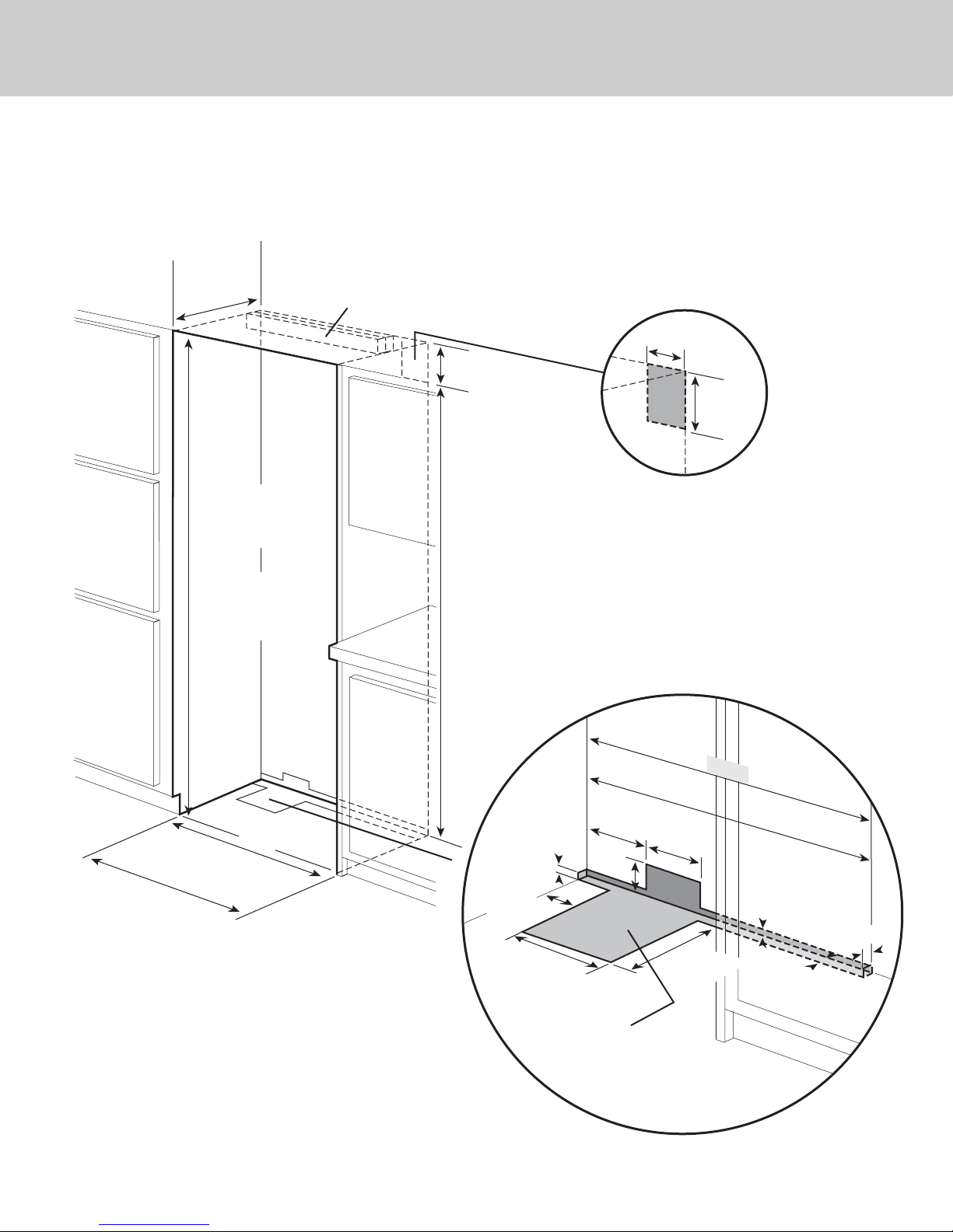
Cutout Dimensions
12
36” All Refrigerator/All Freezer
24”
(61.0 cm)
82–7/8”
(210.5 cm) min.
anti-tip board &
opening height
84–1/16”
(213.5 cm) max.
anti-tip board &
opening height
See Anti-Tip board installation
9”
(22.9 cm)
73–3/8”
(186.4 cm)
Electric Outlet Location
6”
(15.2 cm)
9”
(22.9 cm)
Water Line Entry Area
Note: Shown for All Freezer Only
36”
(91.4 cm)
Flush Mount only
35–5/8”
(90.5 cm) min.
to
35-3/4”
(90.8 cm) max.
(9
1.4 cm)
3
6”
t only
Flush Moun
3–5/8”
(9.2 cm)
(27.3 cm)
5/8”
(1.5 cm)
10–3/4”
water line entry
35–5/8”
7–5/8”
(90.5 cm)
(19.4 cm)
3”
(7.6 cm)
6–3/4”
(17.1 cm)
Optional floor
10–1/2”
(26.7 cm)
5/8”
(1.5 cm)
(1.5 cm)
1”
(2.5 cm)
5/8”
Page 13
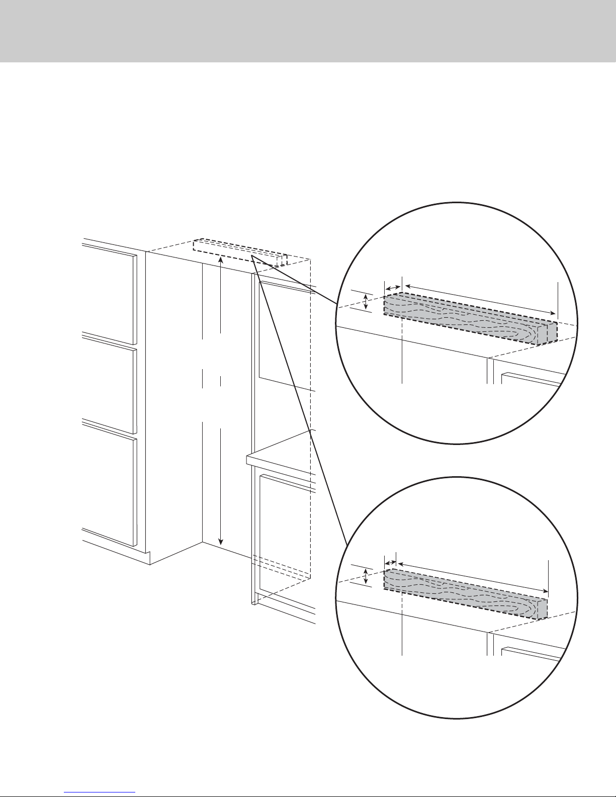
Bottom of anti-tip board is 3–7/8” (9.8 cm) below opening height.
Note: Top of unit must be placed firmly under anti-tip board.
79–3/8”
(201.6 cm) min.
to bottom of
anti-tip board
80–1/2”
(204.6 cm) max.
to bottom of
anti-tip board
Anti-Tip Location
Flush Mount Anti-Tip Location
NOTE: If unit is installed deeper than
24” (61.0 cm), then shim behind the mounting
board by the difference.
NOTE: If unit is installed deeper than
24” (61.0 cm), then shim behind the mounting
board by the difference.
Two 2”x 4” mounting boards
3” (7.6 cm) x 3-1/2” (8.9 cm)
One 2”x 4” mounting board
1–1/2” (3.8 cm) x 3–1/2” (8.9 cm)
29–1/2”
(74.9 cm)
3–1/2”
(8.9 cm)
3”
(7.6 cm)
29–1/2”
(74.9 cm)
3–1/2”
(8.9 cm)
1–1/2”
(3.8 cm)
Anti-Tip Dimensions
13
36” All Refrigerator/All Freezer
Page 14
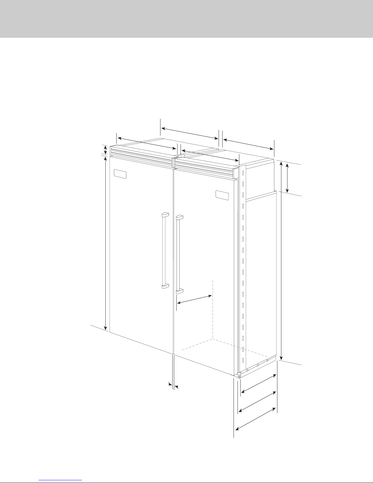
30”
(76.2 cm)
30”
(76.2 cm)
Dimensions
14
Dual 30” All Refrigerator/All Freezer
(76.2 cm)
3–19/32”
(9.1 cm)
(76.2 cm)
30”
30”
29”
(73.7 cm)
30”
30”
(76.2 cm)
(76.2 cm)
29”
(73.7 cm)
75–15/16”
(192 .9 cm
9–5/32”
(23.3 cm)
)
82–3/4”
(210.2 cm)
min.
to
84–1/16”
26-1/2”
(67.3 cm)
(213.5 cm)
max.
1”
(2.54 cm)
Between
Units
20–3/4”
(52.7 cm)
22–3/16”
(56.4 cm)
24”
(61.0 cm)
Page 15
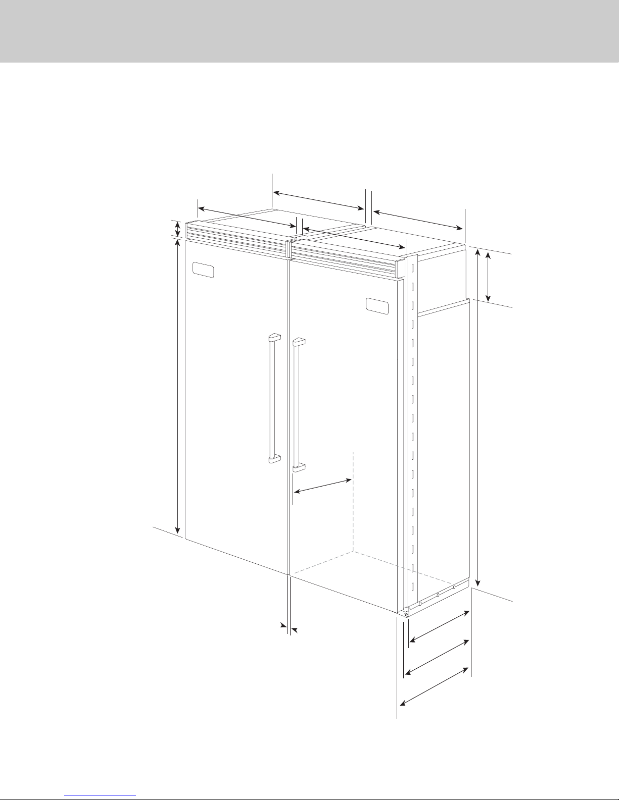
36”
(91.5 cm)
30”
(76.2 cm)
Dimensions
15
Dual 30” & 36” All Refrigerator/All Freezer
30”
30”
(76.2 cm)
3–19/32”
(9.1 cm)
(76.2 cm)
29”
(73.7 cm)
36”
36”
(91.5 cm)
(91.5 cm)
35”
(88.9 cm)
75–15/16”
(192 .9 cm
9–5/32”
(23.3 cm)
)
26-1/2”
(67.3 cm)
82–3/4”
(210.2 cm)
min.
to
84–1/16”
(213.5 cm)
max.
1”
(2.54 cm)
B
etween Units
20–3/4”
(52.7 cm)
cm)
22–3/16”
(56.4
24”
(61.0 cm)
Page 16
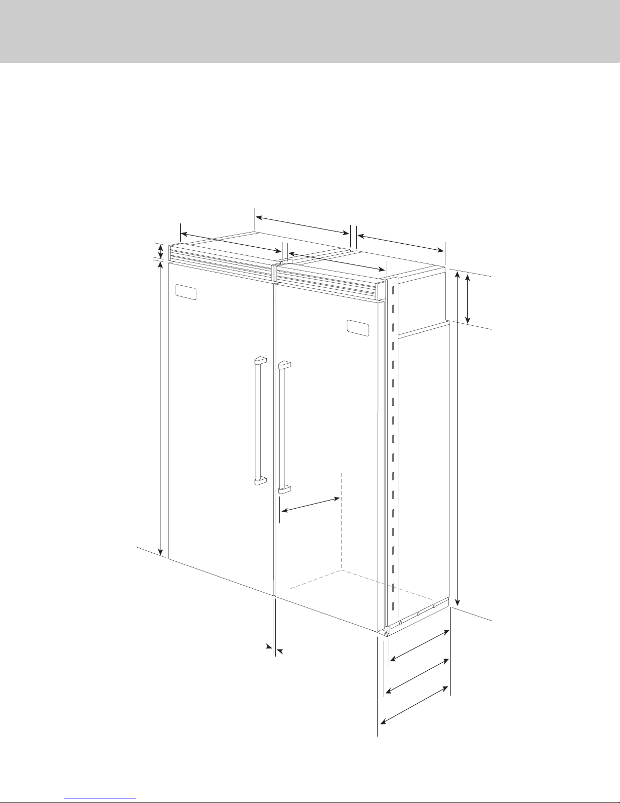
36”
(91.5 cm)
36”
(91.5 cm)
Dimensions
16
Dual 36” All Refrigerator/All Freezer
36”
36”
(91.5 cm)
3–19/32”
(9.1 cm)
(91.5 cm)
35”
(88.9 cm)
(91.5 cm)
(91.5 cm)
36”
36”
35”
(88.9 cm)
75–15/16”
(192 .9 cm
9–5/32”
)
(23.3 cm)
82–3/4”
(210.2 cm)
min.
to
84–1/16”
(213.5 cm)
26-1/2”
(67.3 cm)
max.
1”
(2.54 cm)
Between units
20–3/4”
(52.7 cm)
22–3/16”
(56.4 cm)
24”
(61.0 cm)
Page 17
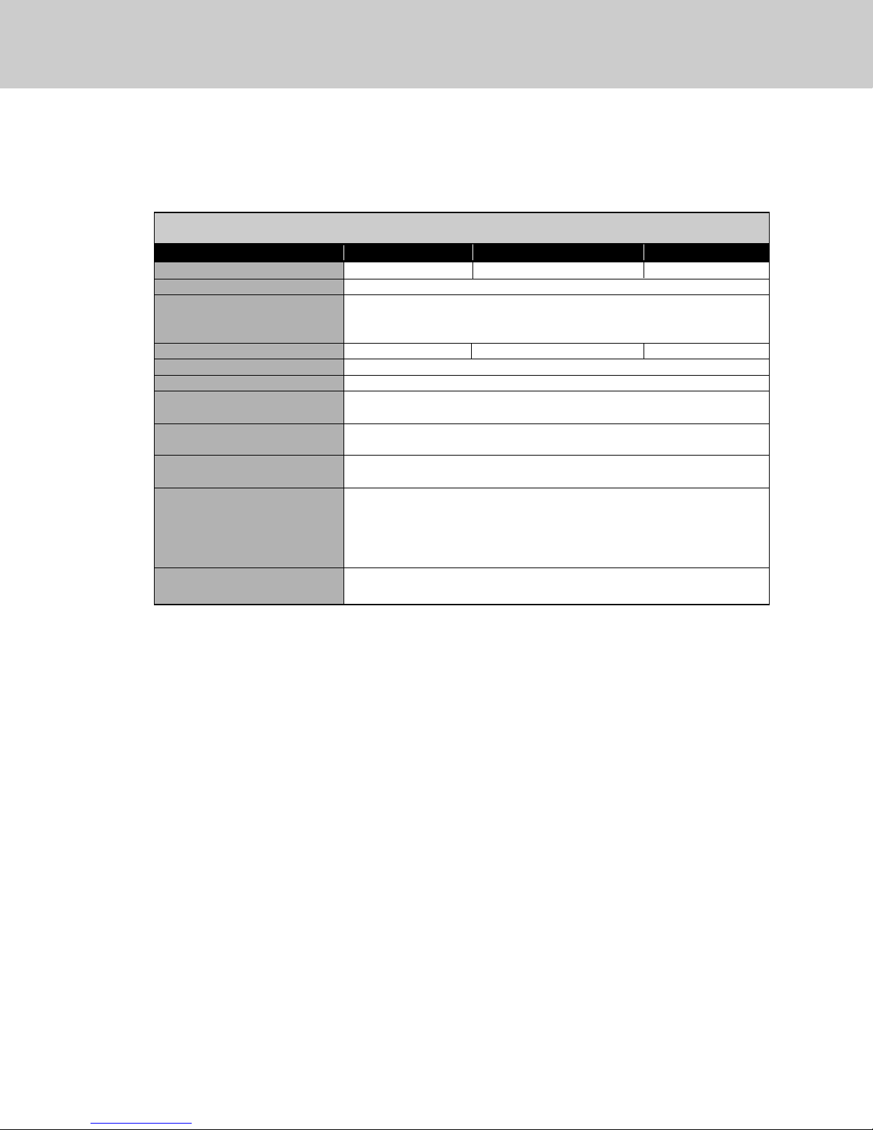
Specifications
17
Dual All Refrigerator/All Freezer*
Description (2) 30” Units (1) 36” & (1) 30” Unit (2) 36” Units
Overall width 60” (152.4 cm) 66” (167.6 cm) 72” (182.9 cm)
Overall height from bottom 82-3/4” (210.2 cm) min. to 84-1/16” (213.5 cm) max.
Overall depth from rear To front edge of side trim: 22-3/16” (56.4 cm)
To front of top grille: 24” (61.0 cm)
To front of handle endcap: 26-1/2” (67.3 cm)
Cutout width 59-5/8” (151.4 cm) 65-5/8” (166.7 cm) 71-5/8” (181.9 cm)
Cutout height 82-7/8” (210.5 cm) min. to 84-1/16” (213.5 cm) max.
Cutout depth 24” (61.0 cm) min.
Electrical requirements (2) 115 volt, 60 Hz, 15 amp dedicated circuit; 3-wire cord with
grounded 3-prong plug attached to product
Maximum amp usage 30” Freezer 9.1 amps per unit 30” Refrigerator 5.7 amps per unit
36” Freezer 9.5 amps per unit 36” Refrigerator 6.5 amps per unit
Inlet water requirements 1/4” copper tubing inlet waterline; minimum 20 psi;
(All Freezer only) maximum 120 psi
Overall interior dimensions
30” Freezer 15.9 cu. ft. (450 liters)
30” Refrigerator 18.4 cu. ft. (522 liters)
36” Freezer 19.2 cu. ft. (544 liters)
36” Refrigerator 22.8 cu. ft. (646 liters)
Approximate shipping weight
30”- Freezer 550 lbs. (247.5 kg) each; Refrigerator 525 lbs. (236.3 kg) each
36”- Freezer 605 lbs. (272.3 kg) each; Refrigerator 590 lbs. (265.5 kg) each
*For installation of two units side-by-side, a separate grille kit accessory must be purchased.
Page 18
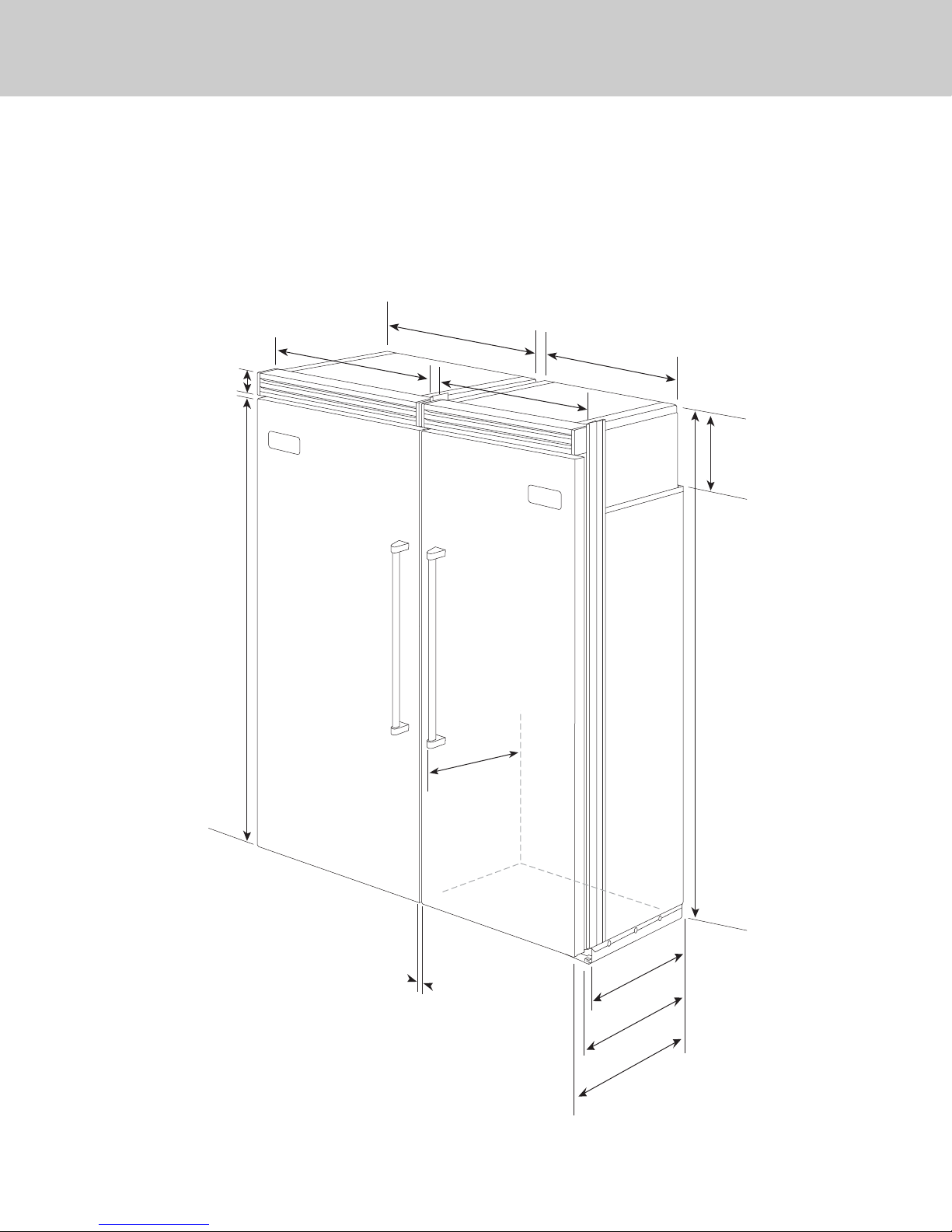
30”
(76.2 cm)
30”
(76.2 cm)
Dimensions
18
Dual 30” All Refrigerator/All Freezer
with Flush Mount Trim
Note: Flush Mount Trim is shipped with the
refrigerator in a box marked “Refrigerator
Trim Parts - DO NOT DISCARD”.
30”
30”
(76.2 cm)
3–19/32”
(9.1 cm)
(76.2 cm)
29”
(73.7 cm)
29”
30”
30”
(76.2 cm)
(76.2 cm)
(73.7 cm)
75–15/16”
(192 .9 cm
9–5/32”
(23.3 cm)
)
82–3/4”
(210.2 cm)
min.
to
84–1/16”
(213.5 cm)
26–1/2”
(67.3 cm)
max.
1”
(2.54 cm)
Between
Units
20–3/4”
(52.7 cm)
23–3/8”
(59.4 cm)
24”
(61.0 cm)
Page 19
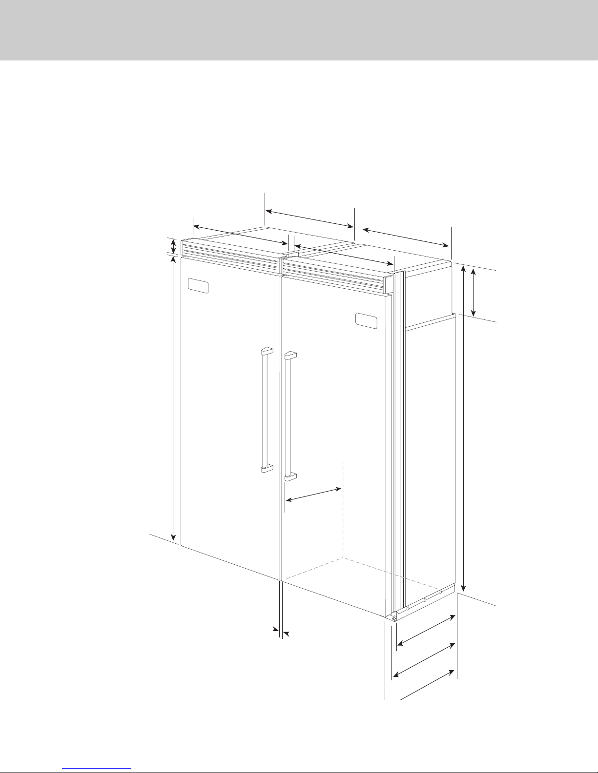
Dimensions
19
24”
(61.0 cm)
1”
(2.54 cm)
B
etween Units
35”
(88.9 cm)
36”36”
(91.5 cm)(91.5 cm)
36”
(91.5 cm)
9–5/32”
(23.3 cm)
82–3/4”
(210.2 cm)
min.
to
84–1/16”
(213.5 cm)
max.
20–3/4”
(52.7 cm)
23–3/8”
(59.4
cm)
29”
(73.7 cm)
75–15/16”
(192 .9 cm
)
3–19/32”
(9.1 cm)
30”30”
(76.2 cm)(76.2 cm)
30”
(76.2 cm)
26–1/2”
(67.3 cm)
Dual 30” & 36” All Refrigerator/All Freezer
with Flush Mount Trim
Note: Flush Mount Trim is shipped with the
refrigerator in a box marked “Refrigerator
Trim Parts - DO NOT DISCARD”.
Page 20
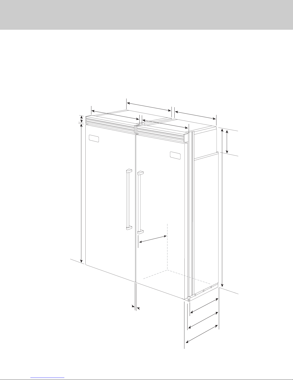
36”
(91.5 cm)
36”
(91.5 cm)
Dimensions
20
Dual 36” All Refrigerator/All Freezer
with Flush Mount Trim
Note: Flush Mount Trim (PBIRFTKSS
purchased separately.
(91.5 cm)
3–19/32”
(9.1 cm)
(91.5 cm)
35”
36”
36”
(88.9 cm)
(91.5 cm)
(91.5 cm)
36”
36”
35”
(88.9 cm)
75–15/16”
(192 .9 cm
9–5/32”
)
(23.3 cm)
82–3/4”
(210.2 cm)
min.
to
84–1/16”
(213.5 cm)
26–1/2”
(67.3 cm)
max.
1”
(2.54 cm)
Between units
20–3/4”
(52.7 cm)
23–3/8”
(59.4 cm)
24”
(61.0 cm)
Page 21
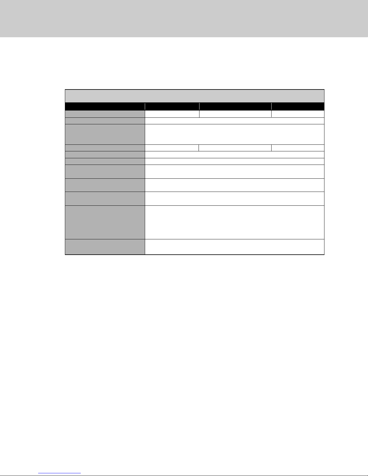
Specifications
21
Dual All Refrigerator/All Freezer w/Flush Mount Trim*
Description (2) 30” Units (1) 36” & (1) 30” Unit (2) 36” Units
Overall width 60” (152.4 cm) 66” (167.6 cm) 72” (182.9 cm)
Overall height from bottom 82-3/4” (210.2 cm) min. to 84-1/16” (213.5 cm) max.
Overall depth from rear To front edge of side trim: 23-3/8” (59.4 cm)
To front of top grille: 24” (61.0 cm)
To front of handle endcap: 26-1/2” (67.3 cm)
Cutout width 60” (152.4 cm) 66” (167.6 cm) 72” (182.9 cm)
Cutout height 82-7/8” (210.5 cm) min. to 84-1/16” (213.5 cm) max.
Cutout depth 24” (61.0 cm) min.
Electrical requirements (2) 115 volt, 60 Hz, 15 amp dedicated circuit; 3-wire cord with
grounded 3-prong plug attached to product
Maximum amp usage 30” Freezer 9.1 amps per unit 30” Refrigerator 5.7 amps per unit
36” Freezer 9.5 amps per unit 36” Refrigerator 6.5 amps per unit
Inlet water requirements 1/4” copper tubing inlet waterline; minimum 20 psi;
(All Freezer only) maximum 120 psi
Overall interior dimensions
30” Freezer 15.9 cu. ft. (450 liters)
30” Refrigerator 18.4 cu. ft. (522 liters)
36” Freezer 19.2 cu. ft. (544 liters)
36” Refrigerator 22.8 cu. ft. (646 liters)
Approximate shipping weight
30”- Freezer 550 lbs. (247.5 kg) each; Refrigerator 525 lbs. (236.3 kg) each
36”- Freezer 605 lbs. (272.3 kg) each; Refrigerator 590 lbs. (265.5 kg) each
*For installation of two units side-by-side, a separate grille kit accessory must be purchased.
Page 22
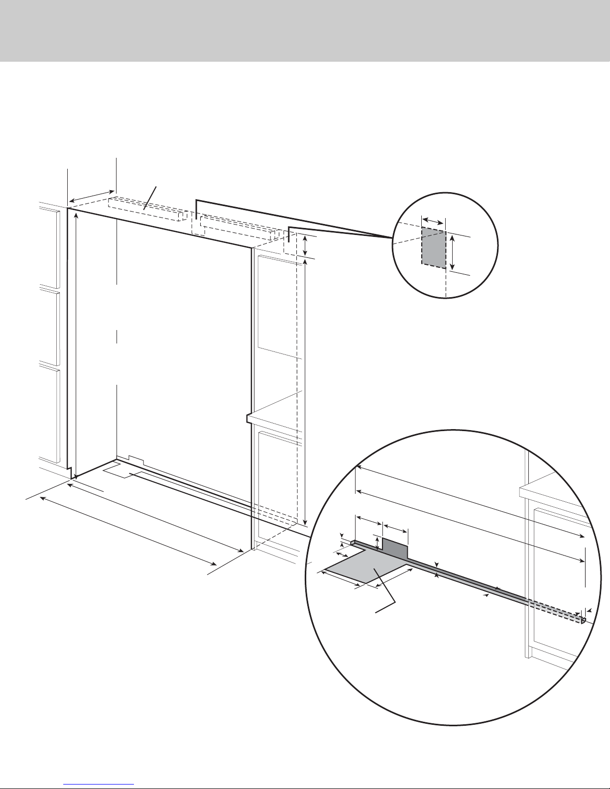
Cutout Dimensions
22
Dual 30” All Refrigerator/All Freezer
24”
(61.0 cm)
82–7/8”
(210.5 cm) min.
anti-tip board &
opening height
84–1/16”
(213.5 cm) max.
anti-tip board &
opening height
See Anti-Tip board installation
Electric Outlet Location
6”
(15.2 cm)
9”
(22.9 cm)
73–3/8”
(186.4 cm)
9”
(22.9 cm)
Water Line Entry Area
Note: Cutout opening shown with All Freezer model on left.
Reverse water line entry if All Freezer model is on right.
(151.4 cm)
Flush Mount only
60”
(152.4 cm)
59–5/8”
(1.5 cm)
3–5/
(9.2 cm
10–3/4”
(27.3 cm)
5
/8”
(7.6 cm)
8
”
)
Optional floor
water li
7–5/8”
(19.4 cm)
3”
n
e entry
6–3/4”
(17.1 cm)
10–1/2”
(26.7 cm)
60”
(152.4 cm)
Flush Mount only
59–5/8”
(151.4 cm)
5
/8”
(1.5 cm)
5/8”
(1.5 cm)
1”
(2.5 cm
)
Page 23
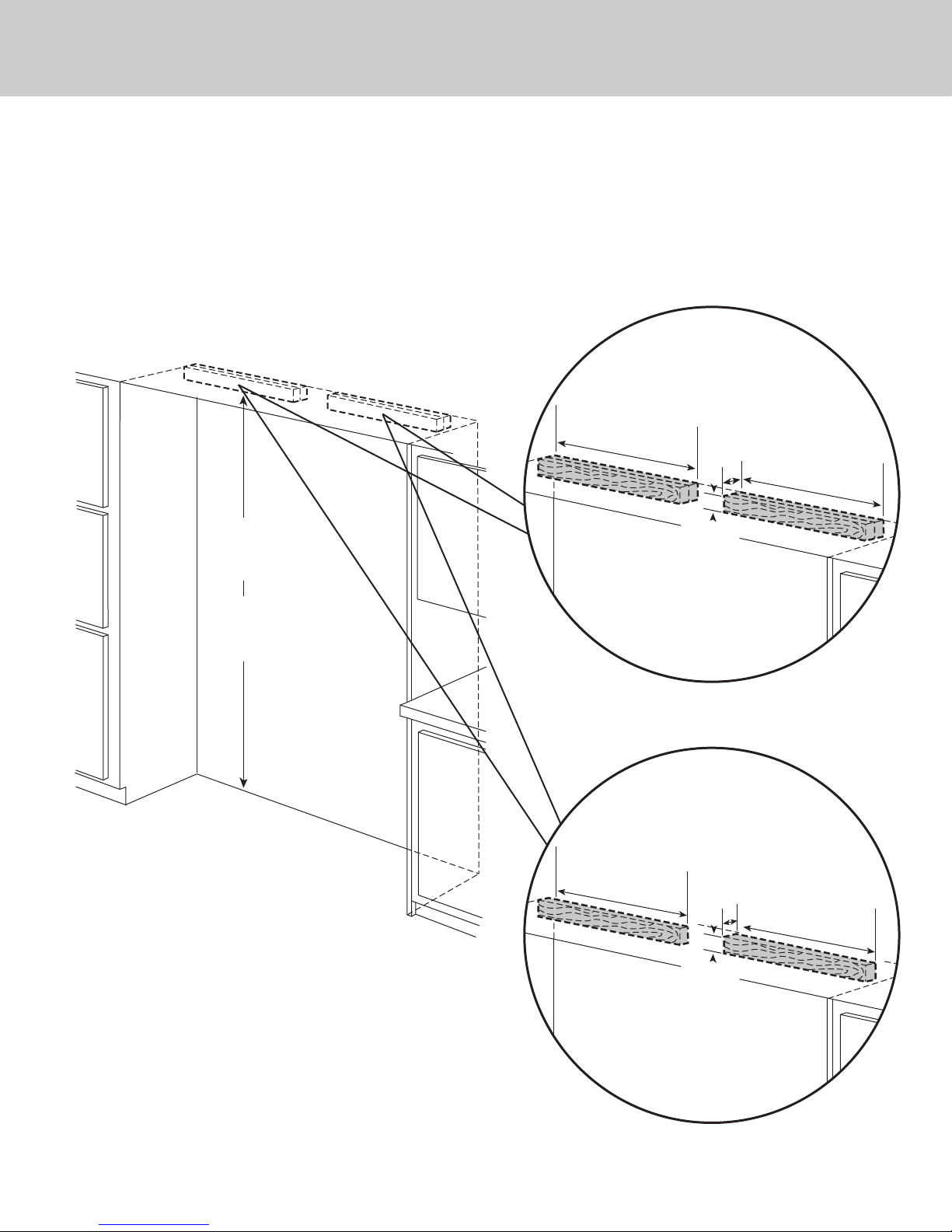
79–3/8”
(201.6 cm) min.
to bottom of
anti-tip board
80–1/2”
(204.6 cm) max.
to bottom of
anti-tip board
One 2”x 4” mounting board per unit
1–1/2” (3.8 cm) x 3–1/2” (8.9 cm)
Two 2”x 4” mounting boards per unit
3” (7.6 cm) x 3–1/2” (8.9 cm)
Note: If unit is installed deeper than
24” (61.0 cm), then shim behind the anti-tip
bracket by the difference.
Note: If unit is installed deeper than
24” (61.0 cm), then shim behind the anti-tip
bracket by the difference.
Bottom of anti-tip board is 3–7/8” (9.8 cm) below opening height.
Note: Top of unit must be placed firmly under anti-tip board.
Anti-Tip Location
Flush Mount Anti-Tip Location
23”
(58.4 cm)
3–1/2”
(8.9 cm)
3”
(7.6 cm)
23”
(58.4 cm)
23”
(58.4 cm)
3–1/2”
(8.9 cm)
1–1/2”
(3.8 cm)
23”
(58.4 cm)
Anti-Tip Dimensions
23
Dual 30” All Refrigerator/All Freezer
Page 24
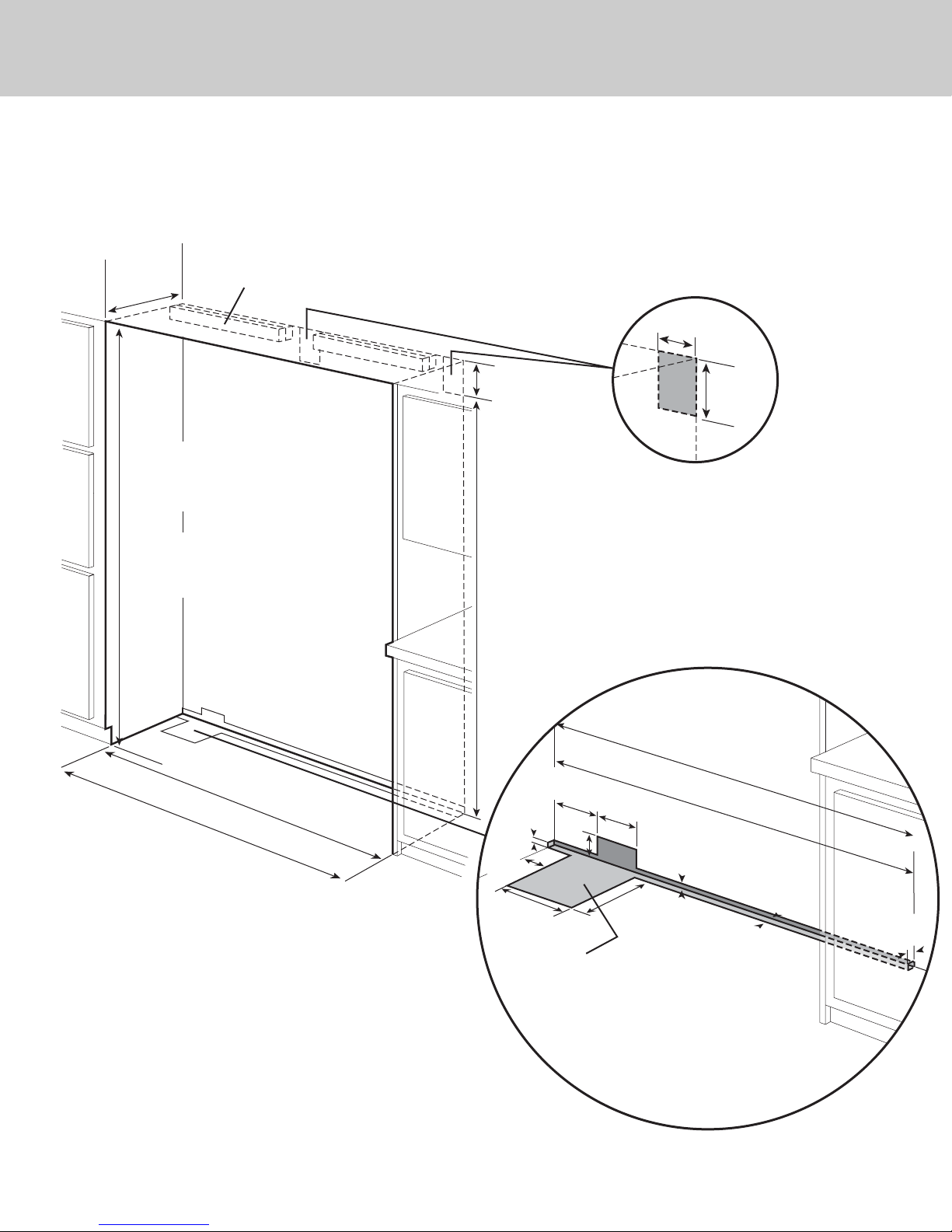
24”
Cutout Dimensions
24
Dual 30” & 36” All Refrigerator/All Freezer
(61.0 cm)
See Anti-Tip board installation
Electric Outlet Location
6”
(15.2 cm)
82–7/8”
(210.5 cm) min.
anti-tip board &
opening height
84–1/16”
(213.5 cm) max.
anti-tip board &
opening height
(1
Flush Mount only
(167.6 cm)
66.7 cm)
66”
65–5/8”
9”
(22.9 cm)
73–3/8”
(186.4 cm)
5
/8”
(1.5 cm)
3–5/
(9.2 cm
8
”
)
10–3/4”
(27.3 cm)
9”
(22.9 cm)
Water Line Entry Area
Note: Cutout opening shown with All Freezer model on left.
Reverse water line entry if All Freezer model is on right.
66”
(167.6
7–5/8”
(19.4 cm)
3”
(7.6 cm)
Optional floor
water li
n
e entry
6–3/4”
(17.1 cm)
10–1/2”
(26.7 cm)
Flush Mount only
(1.5 cm)
5
/8”
cm)
65–5/8”
(166.7 cm)
5/8”
(1.5 cm)
1”
(2.5 cm
)
Page 25
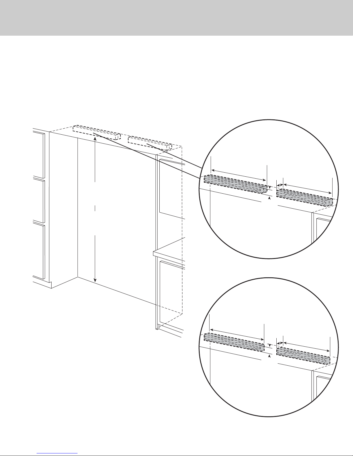
Anti-Tip Dimensions
25
Dual 30” & 36” All Refrigerator/All Freezer
79–3/8”
(201.6 cm) min.
to bottom of
anti-tip board
80–1/2”
(204.6 cm) max.
to bottom of
anti-tip board
Anti-Tip Location
Two 2”x 4” mounting boards per unit
3” (7.6 cm) x 3 1/2” (8.9 cm)
29”
(73.7 cm)
Note: If unit is installed deeper than
24” (61.0 cm), then shim behind the mounting
boards by the difference.
3–1/2”
(8.9 cm)
3”
(7.6 cm)
(58.4 cm)
23”
Bottom of anti-tip board is 3–7/8” (9.8 cm) below opening height.
Note: Top of unit must be placed firmly under anti-tip board.
Note: Dimensions shown for 36” AF/AR model on the left.
Reverse mounting boards if units are installed on the right.
Flush Mount Anti-Tip Location
One 2”x 4” mounting board per unit
1–1/2” (3.8 cm) x 3–1/2” (8.9 cm)
29”
(73.7 cm)
Note: If unit is installed deeper than
24” (61.0 cm), then shim behind the mounting
boards by the difference.
1–1/2”
3–1/2”
(8.9 cm)
(3.8 cm)
(58.4 cm)
23”
Page 26
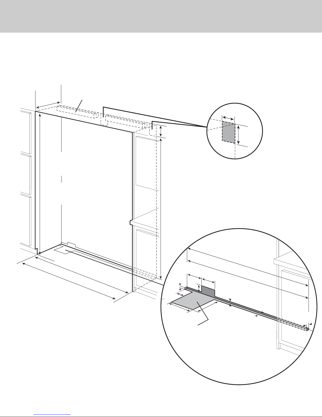
Cutout Dimensions
26
Dual 36” All Refrigerator/All Freezer
24”
(61.0 cm)
82–7/8”
(210.5 cm) min.
anti-tip board &
opening height
84–1/16”
(213.5 cm) max.
anti-tip board &
opening height
See Anti-Tip board installation
9”
(22.9 cm)
73–3/8”
(186.4 cm)
Electric Outlet Location
6”
(15.2 cm)
9”
(22.9 cm)
Water Line Entry Area
Note: Cutout opening shown with All Freezer model on left.
Reverse water line entry if All Freezer model is on right.
(1
Flush Mount only
(1
72”
82.8 cm)
81.9 cm)
71–5/8”
5
(1.5 cm)
3–5/
(9.2 cm
10–3/4”
(27.3 cm)
7–5/8”
(19.4 cm)
/8”
3”
(7.6 cm)
8
”
)
Optional floor
water li
n
e entry
6–3/4”
(17.1 cm)
10–1/2”
(26.7 cm)
72”
(18
2.8 cm)
Flush Mount only
71–5/8”
(181.9 cm)
5
/8”
(1.5 cm)
5/8”
(1.5 cm)
1”
(2.5 cm
)
Page 27
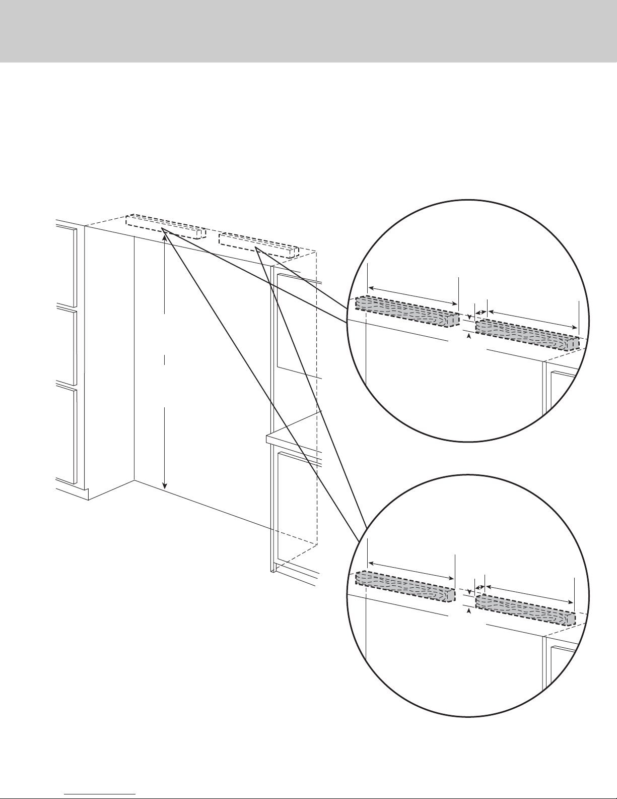
Anti-Tip Dimensions
27
Dual 36” All Refrigerator/All Freezer
79–3/8”
(201.6 cm) min.
to bottom of
anti-tip board
80–1/2”
(204.6 cm) max.
to bottom of
anti-tip board
Anti-Tip Location
Two 2”x 4” mounting boards per unit
3” (7.6 cm) x 3–1/2” (8.9 cm)
29”
(73.7 cm)
Note: If unit is installed deeper than
24” (61.0 cm), then shim behind the mounting
boards by the difference.
(7.6 cm)
3–1/2”
(8.9 cm)
3”
(73.7 cm)
29”
Bottom of anti-tip board is 3–7/8” (9.8 cm) below opening height.
Note: Top of unit must be placed firmly under anti-tip board.
Flush Mount Anti-Tip Location
One 2”x 4” mounting board per unit
1–1/2” (3.8 cm) x 3–1/2” (8.9 cm)
29”
(73.7 cm)
Note: If unit is installed deeper than
24” (61.0 cm), then shim behind the mounting
boards by the difference.
1–1/2”
(3.8 cm)
3–1/2”
(8.9 cm)
(73.7 cm)
29”
Page 28
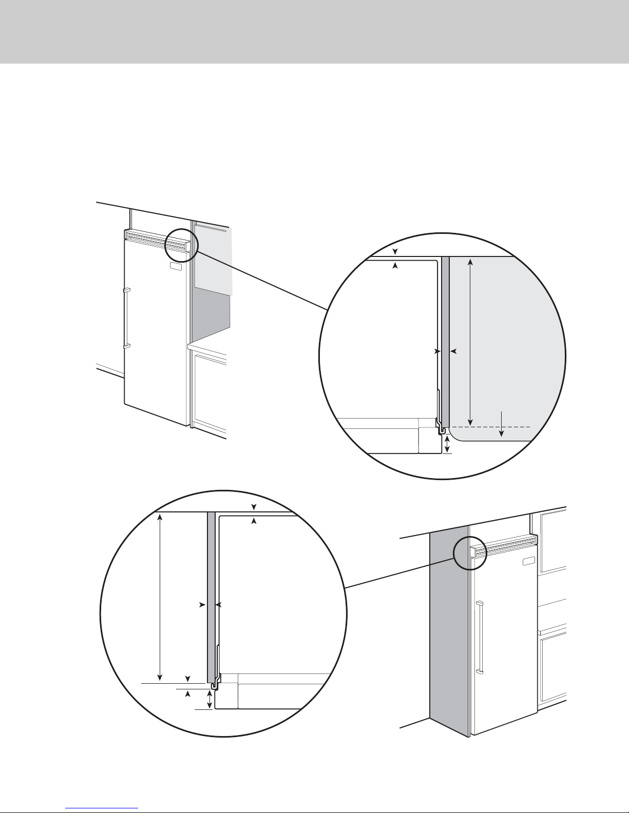
Cabinet Information
28
Professional models fit “semi-flush” in standard 24” (61.0 cm) deep cabinet openings. The door
face protrudes 1-3/4” (4.4 cm) from the cabinet face. The handle protrudes an additional
2-1/2” (6.4 cm) into the room.
Top View
Wall
1–13/16”
(4.6 cm)
Space if 24” (61.0 cm)
standard cabinet
depth is used
24”
Standard cabinet depth
3/4”
(1.9 cm)
Full end panel
(61.0 cm)
Top View
24”
(61.0 cm)
Standard
cabinet depth
5–16”
(0.8 cm)
Countertop overhang
Door
1-3/4”
(4.4 cm) Offset
Wall
1–13/16”
(4.6 cm)
Space if 24” (61.0 cm)
standard cabinet
depth is used
3/4”
(1.9 cm)
Full end panel
1-3/4”
(4.4 cm) Offset
Door
Page 29
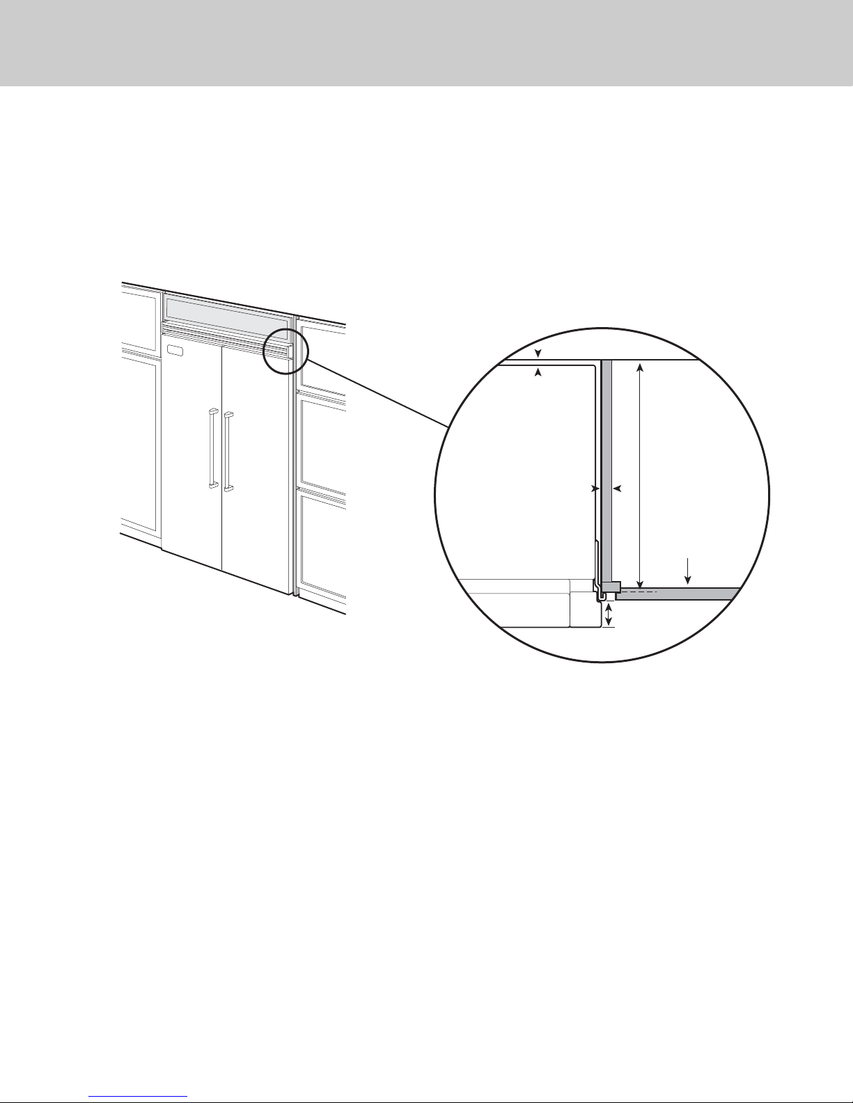
Cabinet Information
29
Professional models fit “semi-flush” in standard 24” (61.0 cm) deep cabinet openings. The door
face protrudes 1-3/4” (4.4 cm) from the cabinet face. The handle protrudes an additional
2-1/2” (6.4 cm) into the room.
Top View
Wall
1–13/16”
(4.6 cm)
Space if 24” (61.0 cm)
standard cabinet
depth is used
24”
Standard cabinet depth
3/4”
(1.9 cm)
Full end panel
(61.0 cm)
Partial overlay
cabinet door
Door
1-3/4”
(4.4 cm) Offset
Page 30
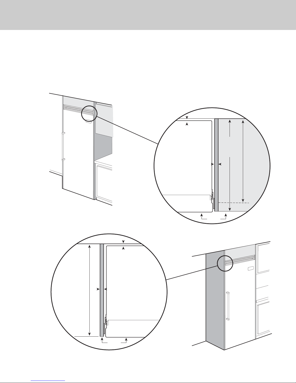
Cabinet Information (With Flush Mount Trim)
30
Models with flush mount trim fit flush in standard 24” (61.0 cm) deep cabinet openings with no
protrusion into the room except the handle protrudes 2-1/2” (6.4 cm) into the room.
Top View
Wall
1”
(2.5 cm)
space if
25” (63.5 cm)
cabinet depth
is used
3/4”
(1.9 cm)
Full end panel
25”
(63.5 cm)
countertop
depth
24”
(61.0 cm)
Standard
cabinet
depth
25”
(63.5 cm)
Door
Flush
Top View
Wall
1”
(2.5 cm)
space if
25” (63.5 cm)
cabinet depth
is used
3/4”
(1.9 cm)
Full end panel
Door
Flush
Page 31
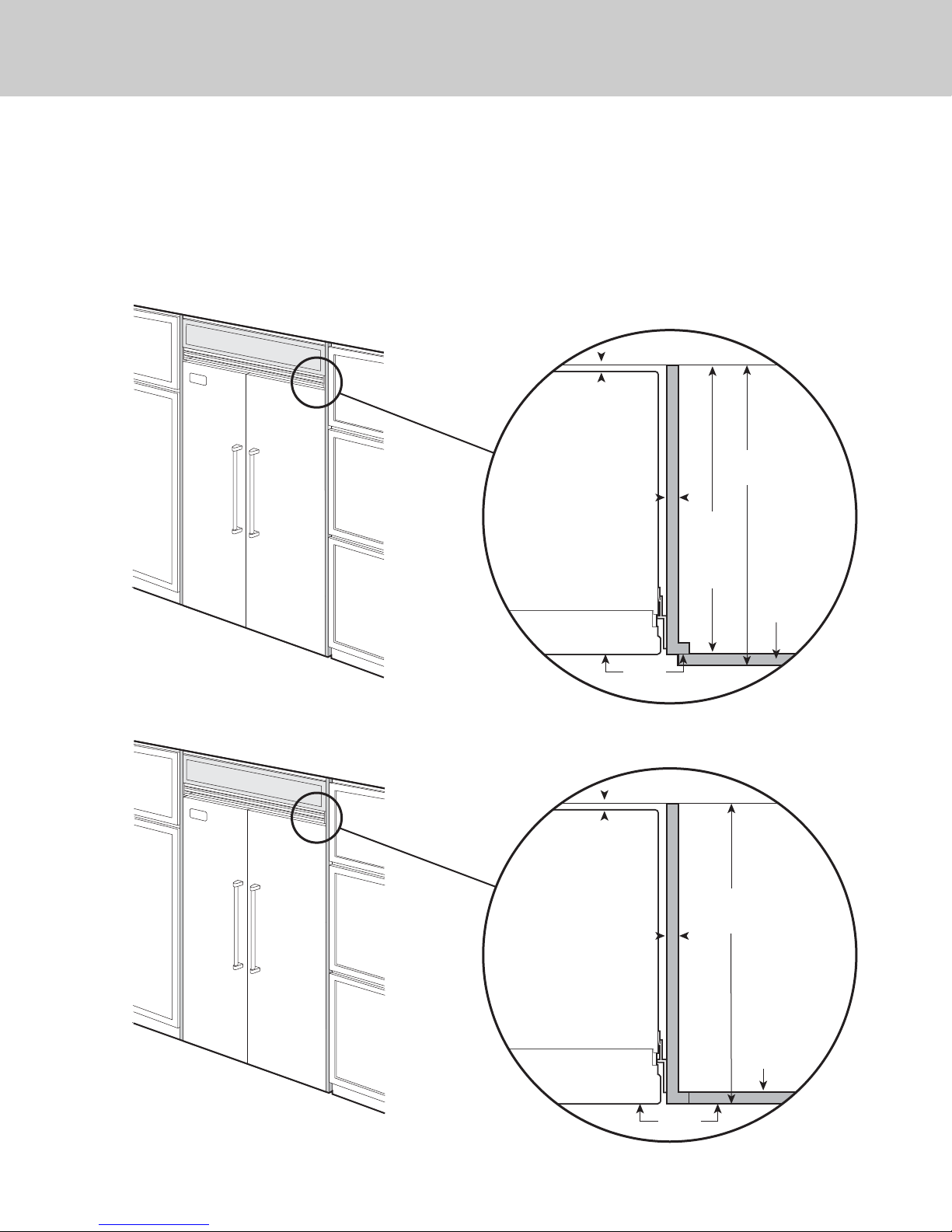
Cabinet Information (With Flush Mount Trim)
31
Models with flush mount trim fit flush in standard 24” (61.0 cm) deep cabinet openings with no
protrusion into the room except the handle protrudes 2-1/2” (6.4 cm) into the room.
Top View
Overlapping cabinet doors
Wall
3/4”
(1.9 cm)
space if
24” (61.0 cm)
standard
cabinet depth
is used
3/4”
(1.9 cm)
Full end panel
Door
24-3/4”
(62.9 cm)
24”
(61.0 cm)
Standard
cabinet
depth
Cabinet door
Flush
Top View
Flush mount cabinet doors
Wall
1”
(2.5 cm)
space if
25” (63.5 cm)
cabinet depth
is used
3/4”
(1.9 cm)
Full end panel
Door
Cabinet depth
Flush
25”
(63.5 cm)
Cabinet door
Page 32
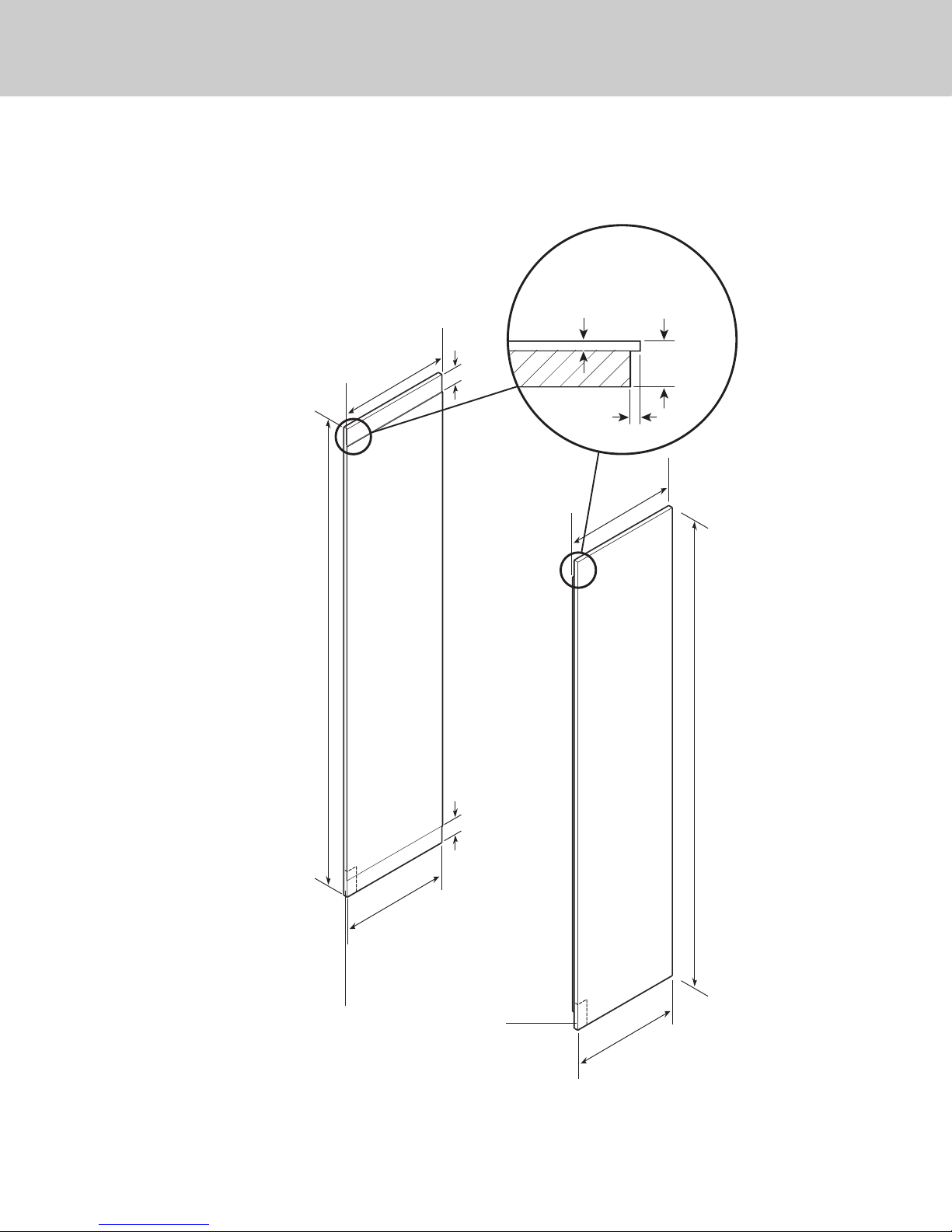
3/4”
(1.9 cm)
End panel
5/32”
(0.4 cm)
3/16”
(0.5 cm)
Back filler
panel
Custom Side Panel Dimensions
32
* Depending on how high leveling feet are raised, and cabinet enclosure height.
6”
(15.2 cm)
22-7/16”
(57.0 cm)
82-7/8”
(210.5 cm) min.
to
84-1/16”
(213.5 cm) max.*
22-7/16”
(57.0 cm)
Optional kickplate notch
Dimensions determined by cabinets
22-1/4”
(56.5 cm)
6”
(15.2 cm)
22-1/4”
(56.5 cm)
82-7/8”
(210.5 cm) min.
to
84-1/16”
(213.5 cm) max.*
Page 33
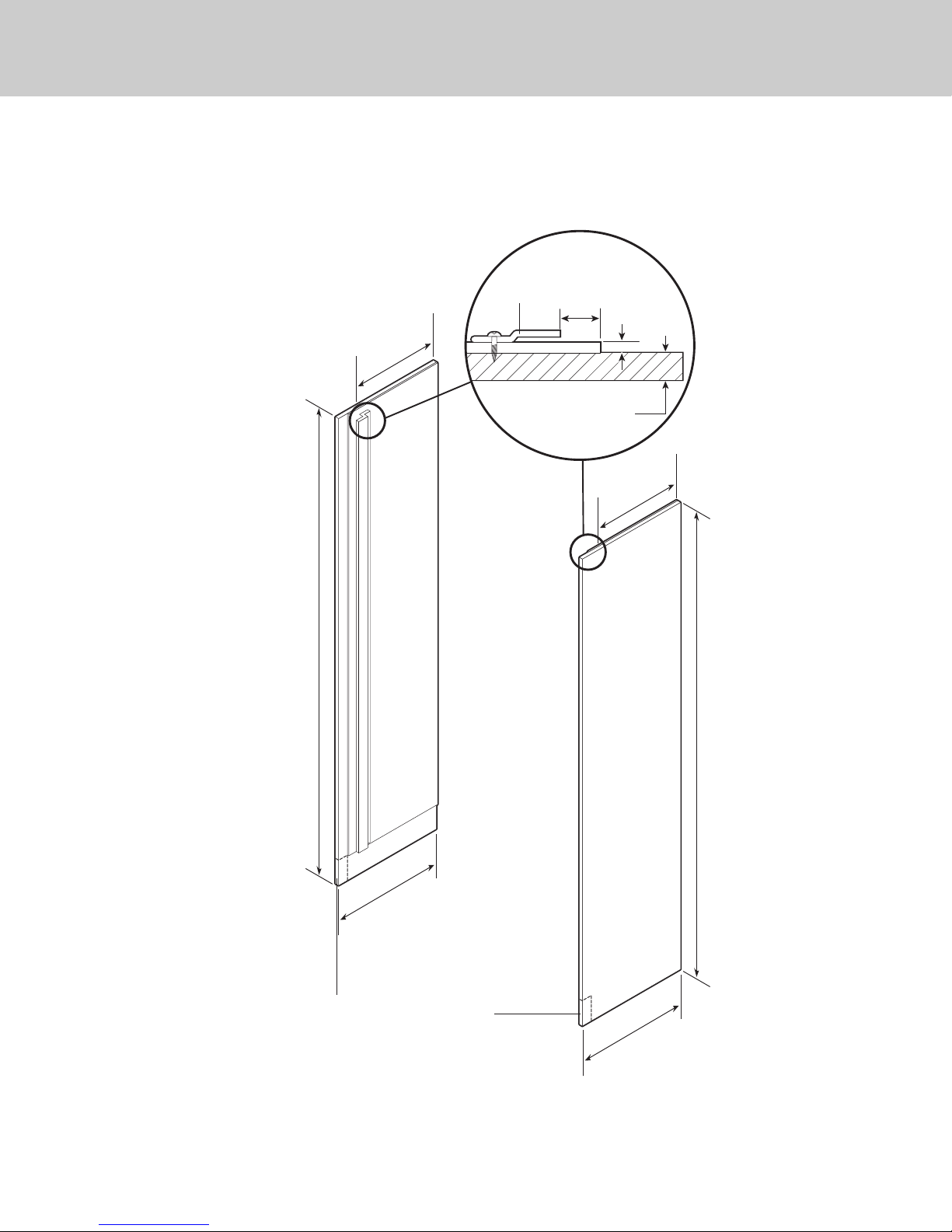
3/4”
(1.9 cm)
End panel
1”
(2.5 cm)
1/4”
(0.6 cm)
Z-Bracket
Custom Side Panel Dimensions
(With Flush Mount Trim)
33
* Depending on how high leveling feet are raised, and cabinet enclosure height.
21-3/4”
(55.2 cm)
21-3/4”
(55.2 cm)
82-7/8”
(210.5 cm) min.
to
84-1/16”
(213.5 cm) max.*
Optional kickplate notch
Dimensions determined by cabinets
24”
(61.0 cm)
24”
(61.0 cm)
82-7/8”
(210.5 cm) min.
to
84-1/16”
(213.5 cm) max.*
Page 34

34
General Information
Area Requirements
Verify the following:
• Unit can fit into residence and can be
moved around corners and through
doorways.
• Floors can support unit’s weight plus food
weight (approximately 1200 pounds
[540 kg] per unit).
• Floors underneath appliance are level with
surrounding finished floor.
• Rear wall is solid and is able to support
two horizontally mounted 2 X 4s (included)
bolted to two wall studs. The 2 X 4 board
bolt heads must be flush with 2 X 4 to
prevent obstruction.
• Remove anything attached to rear or side
walls that can obstruct unit installation.
• Cutout dimensions are accurate.
• Electrical outlet is in correct location.
• Water line is in correct location.
• Do not install a refrigeration unit near a
heat source, nor in a location where the
surrounding temperature will fall below
60º F (16º C).
Electrical Requirements
It is the customer’s responsibility to:
• contact a qualified electrical installer.
• assure that the electrical installation is
adequate and in conformance with the
National Electrical Code, ANSI/NFPA 70latest edition or Canadian Electrical Code
C22.1-1998 and C22.2 No. 0-M91 (or
latest edition), and all local codes and
ordinances. A 115 volt, 60-Hz, 15 amp,
fused, electrical supply is required.
It is required that a separate circuit serving
only this appliance be provided. This
appliance is equipped with a power supply
cord having a 3-prong grounding plug. To
minimize possible shock hazard, the cord
must be plugged into a mating 3-prong,
grounding-type wall receptacle.
Do not use an extension cord.
If codes permit a separate grounding wire to
be used, it is recommended that a qualified
electrician determine that the grounding
path is adequate.
DO NOT ground to a gas pipe. Check with a
qualified electrician if you are not sure the
appliance is properly grounded. DO NOT
have a fuse in the neutral or grounding
circuit.
Anti-Tip Requirements
The anti-tip boards should be fastened into
position prior to moving the unit into the
opening.
Note: Additional mounting boards may be
required if the unit does not touch the back
wall of the enclosure. To prevent unit from
tipping forward, it must be secured in place
with a solid soffit or wood block.
Page 35
35
General Information
Water Supply Requirements
(All Freezer)
Use only 1/4” (6 mm) copper tubing for
water line. Do Not install copper tubing in
area where temperatures drop below
35° F (1.7° C). Before attaching copper
tubing to the unit, flush at least 2 quarts (1.9
L) of water through the copper tubing and
into a bucket to remove any particles in the
water line.
• Viking Range, LLC is not responsible for
property damage due to improper
installation or water connection.
• Connect 1/4” (6 mm) flexible copper
tubing to household plumbing in
compliance with local codes and
ordinances.
• Length of copper tubing must reach from
water supply connection to the unit
connection with an additional length to
facilitate moving the unit out of enclosure
for cleaning or service. Tubing should be
soft instead of rigid and ends should be
free of burrs.
• Copper tubing route must be above 35° F
(1.7° C) to prevent water line from freezing.
• Do not use plastic water lines from the
household plumbing to the water inlet
valve connection on the unit.
• Do not use the self-piercing feature of a
saddle valve. The hole made by the
piercing lance is too small for the water
flow rate required by the ice maker.
• If saddle valve is not used, place a
separate shut-off valve in an easily
accessible location between water supply
and the unit. Do not locate shut-off valve
behind the unit.
• The installation of Viking units with a
reverse osmosis system is acceptable
as long as the water pressure remains
within the allowable PSI as stated below. It
is important to note that with many reverse
osmosis systems, the pressure starts off
high, but then it decreases as the water
level of the reverse osmosis storage area
drops. This must be considered when
checking the water pressure coming into
the unit.
• Connect a vertical or horizontal 1/2”
(1.2 cm) to 1-1/4” (3.2 cm) COLD water
line near water area.
• Run water line through the floor, back, or
side wall. Tubing should lay flat on floor
underneath the unit. Clamp tubing to wall
or floor.
• Water pressure must be greater than 20 psi
and less than 120 psi on non-dispensers
and greater than 35 psi and less than 120
psi on dispensers.
WARNING
To avoid serious illness or death, do not use unit
where water is microbiologically unsafe or of
unknown quality without adequate disinfection
before or after the system. Systems certified for cyst
reduction may be used on disinfected water that
may contain filterable cysts. The contaminants or
other substances removed or reduced by this water
treatment system are not necessarily in you water.
Page 36
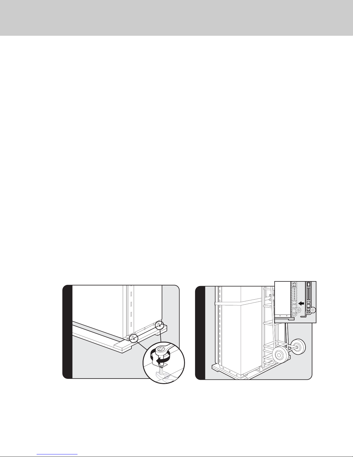
• Most of the unit’s weight is at the top.
Extra care is needed when moving the unit
to prevent tipping.
• Do Not remove protective film until unit is
in operating position.
• All four leveling legs must contact the floor
to support and stabilize the full weight.
• Do not drop unit.
• Remove exterior shipping materials prior
to moving unit into home.
• Use two or more people to move and
install unit. Failure to follow this instruction
can result in back or other injury.
• To avoid personal injury, wear gloves when
performing any installation procedure and
wear eye protection when cutting metal
straps.
Tip Over Hazard
Appliance is top heavy and tips easily when
not completely installed. Keep doors closed
until appliance is completely installed and
secured per installation instructions. Use two
or more people to move and install
appliance. Failure to do so can result in
death or serious injury.
Unpacking unit
1. Remove top and bottom strap.
2. Remove top cap.
3. Cut carton rear approximately 1/4”
(0.6 cm) to 1” (2.5 cm) from right corner
with a utility knife extended 1/4” (0.6 cm).
4. Remove carton and exterior packaging.
Save cardboard shipping material to
protect floor surface when installing unit.
Remove anti-tip board, kickplate and door
trim pieces (DF models) from rear of unit.
36
Moving Unit
Remove shipping brackets from skid by removing 4 bolts
(2 on each side) with a 1/2” deep-well socket wench and
a pair of pliers.
Note: Tilting unit is not required to remove shipping
brackets.
Slip appliance dolly between unit and skid. Only use
dolly from the rear of the unit to remove unit from skid.
After the unit is removed from the skid, a dolly can be
used from either side or the back BUT NOT THE FRONT.
Note: Use excess packaging to protect decorative trim;
also, verify that leveling legs are up (0” adjustment).
General Information
Page 37
37
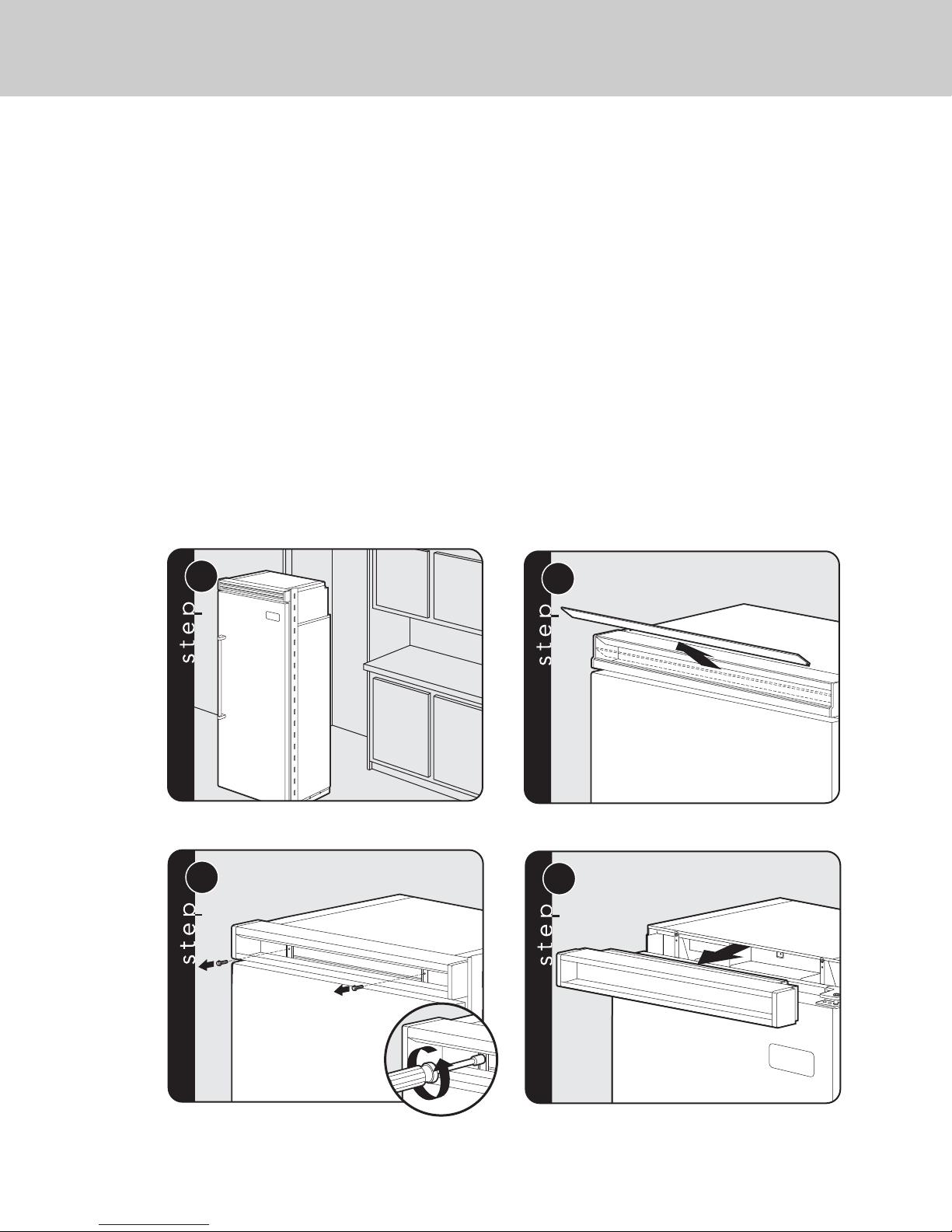
1
2
Place unit in front of cutout.
Pull the center grille louver up
at an angle and pull out.
3
4
Using an 8” magnetic nut driver, remove
the two 1/4” screws.
Remove grille assembly.
Installation
Flush Mount Side Trim Installation
Note: If the unit is to be installed flush with the cabinets, the flush mount side trim must be
installed first. If not, skip to “installation”.
Step 1 - Locate the necessary parts: Two (2) flush mount trim pieces and a hardware kit with
twenty-two (22) screws.
Step 2 - Remove the side trim on the refrigerator and discard the trim and screws.
Step 3 - Align the top of the flush mount side trim with the top of the unit's machine
compartment. Using the screws included in the hardware kit, attach the side trim to the unit,
only using the holes visible through the side trim. Note: Do not use the screw holes in the
machine compartment.
Page 38
38
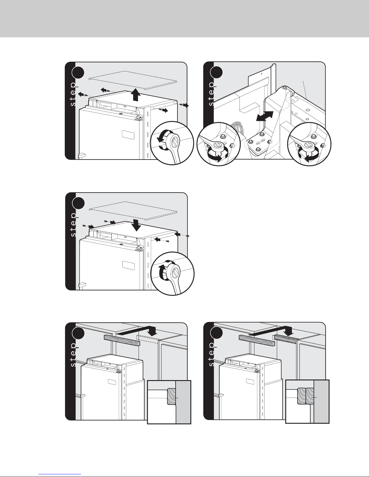
Remove 4 side screws and remove unit top.
Loosen the 4 hinge screws. Adjust door.
Retighten 4 hinge screws.
Replace unit top. Replace 4 side screws.
Attach a single 2 x 4 to wall stud (refer to dimensions
page for exact location).
If needed, depending on cabinet and depth,
attach second 2 x 4 to first 2 x 4.
2
1
5
Front of unit
2
1 3
6
1
2
7
8a
Wall
2 x 4
Refrigerator
8b
Wall
2 x 4
Refrigerator
Hinge Adjustment
Page 39
39
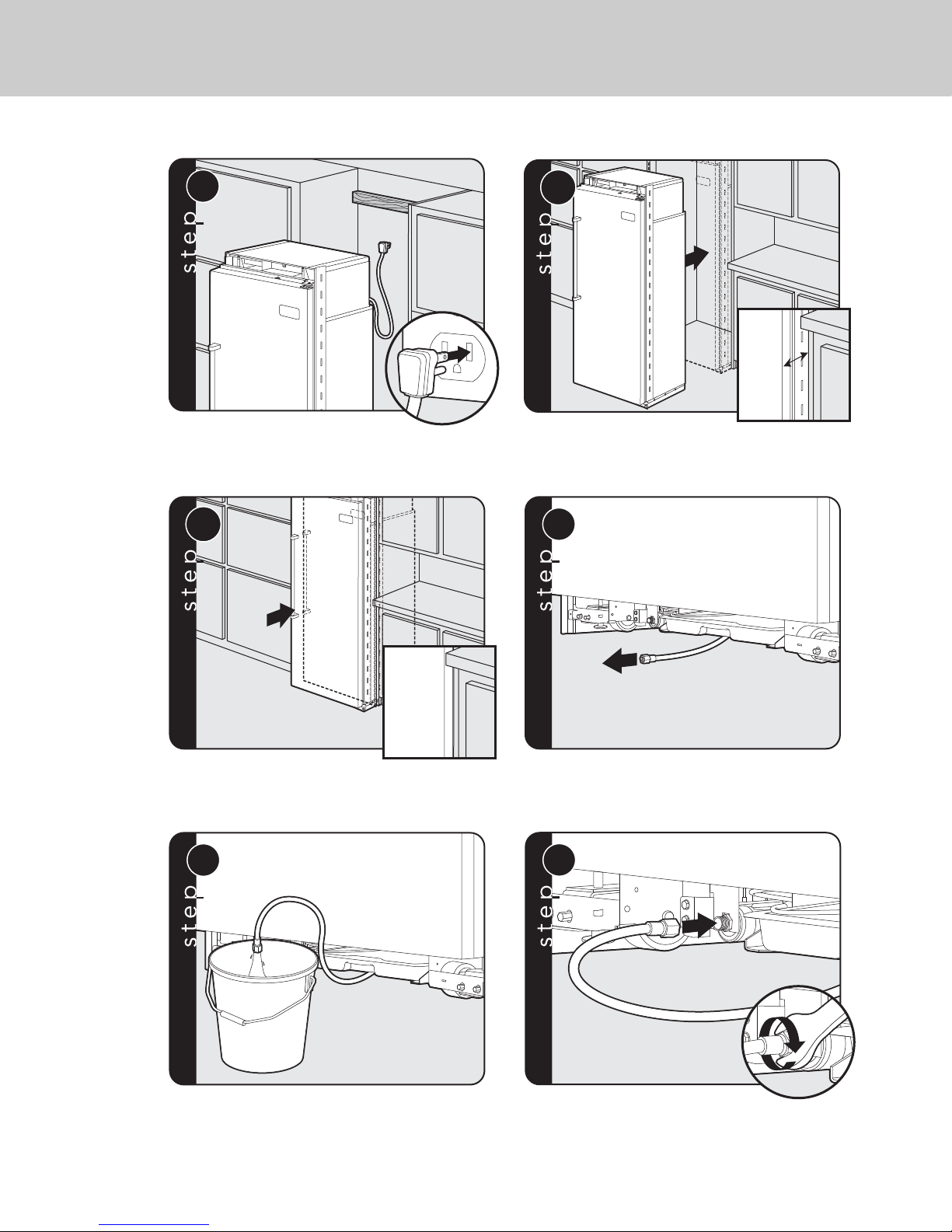
9
3”3”3”
10a
Plug in power cord to verify operation.
Note: Make sure power switch and showroom switch
are in the “On” Position.
Place unit within 3” of being flush with cabinets.
Note: To avoid cabinet damage, place cardboard
between cabinets and unit. When moving unit, do not
crimp, kink or crush water supply line.
10b
11
Carefully move unit until semi flush with cabinet
(depending on unit).
Pull supply tubing forward under unit.
Note: DO NOT use plastic water lines.
12
13
Flush water line by running two quarts of water
into a bucket. Turn water off.
Connect supply tube to water valve using
a 1/2” wrench.
Note: DO NOT overtighten.
Page 40
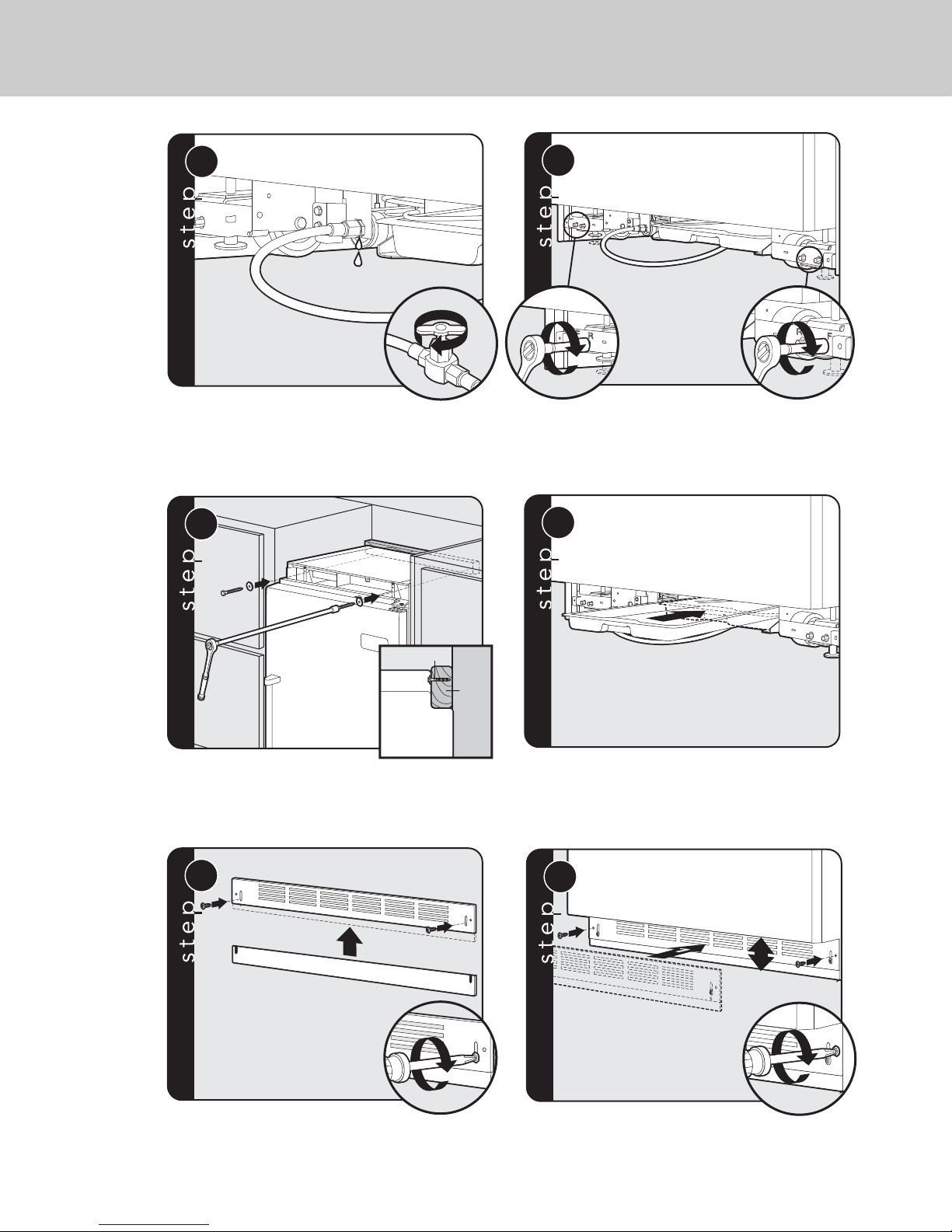
40
Turn on water supply and check for leaks.
Lift unit off rollers to desired height and level unit using
a 5/16” head wrench.
Note: DO NOT use an electric device. Overtightening
can cause damage.
Attach positive secure self-tapping bolts to 2 x 4
using a 22” extension.
Verify that drain pan is installed and aligned.
Align holes on both ends of louvered panels and insert
screws.
Using a Phillips screwdriver, attach the
kickplate to the unit and adjust to desired height.
14
15
Wall
2 x 4
Refrigerator
Screw
16
17
1
2
18
2
3
19
Kickplate Installation
Page 41
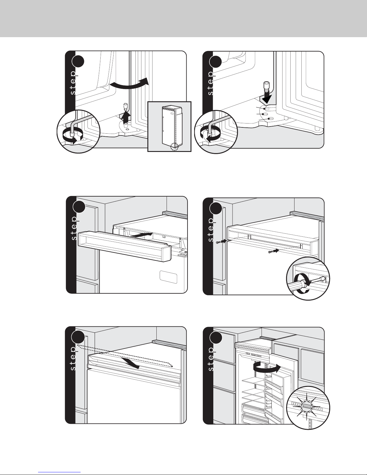
41
3
1
2
20
1
2
21
110˚
120˚
90˚
Open refrigerator door so door stop and shoulder
screw are accessible.
Note: Shoulder screw should be in 110˚ door opening position.
Remove shoulder screw and place in 90˚ or
120˚ position.
Door Stop Adjustment
Replace top air grille.
Using an 8”magnetic nut driver, replace
the two 1/4” screws.
Replace the center grille louver.
Open door. Display should flash.
22
23
24
25
Final Installation
Page 42
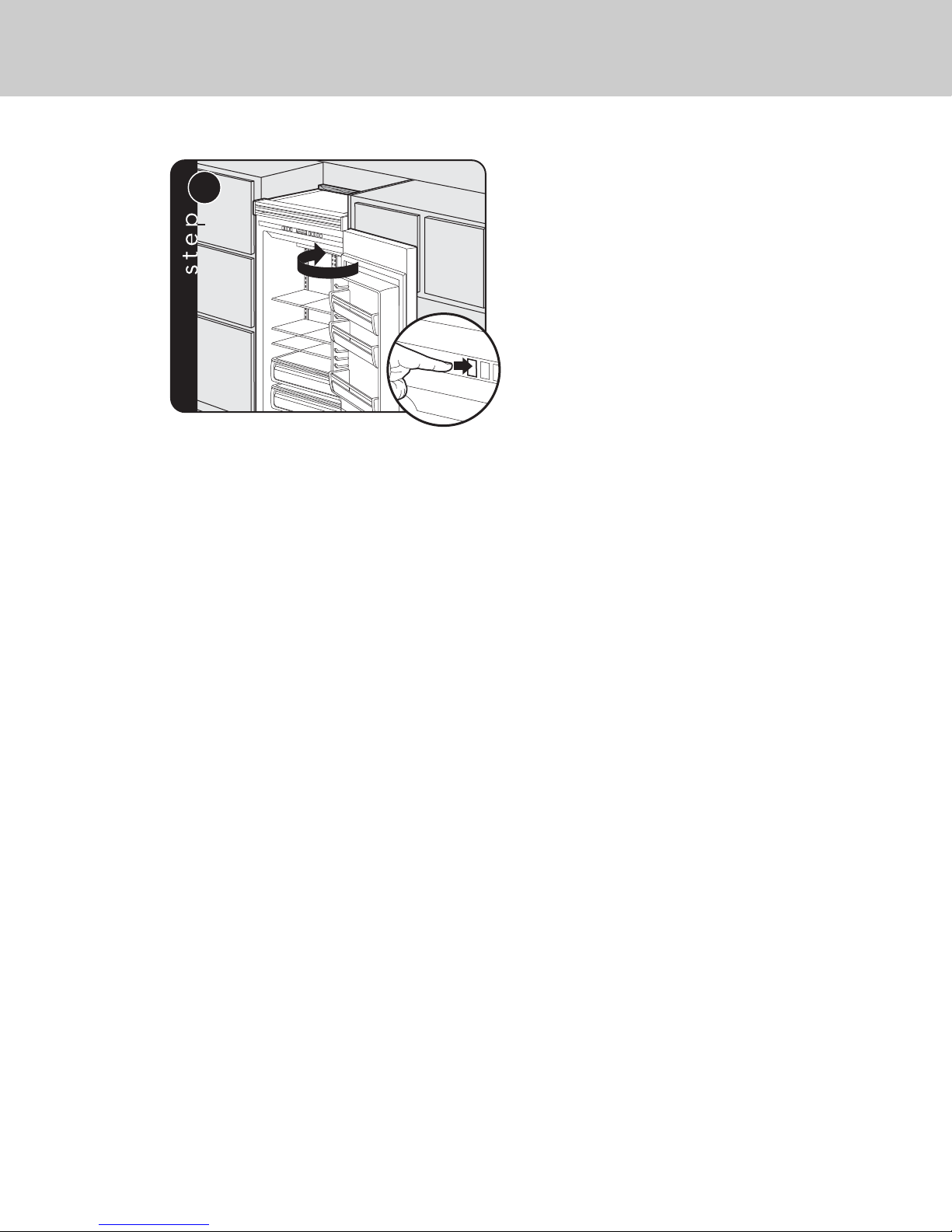
42
Press “ACTIVATE CONTROLS” button pad and close
door.
Note: There is a 6 minute delay before the unit starts.
26
Page 43

Performance Checklist
43
Verify cabinet size.
Verify electrical supply and water supply
(if applicable).
Install anti-tip device(s) and verify unit is
secure.
Position unit in cutout, level at desired
height, and secure unit.
Plug-in unit and verify operation.
Connect water supply (if applicable).
• Verify icemaker fill tube is properly
inserted.
• Verify icemaker bailarm is down.
Align/square door(s).
Verify drain pan is properly installed and
there are no leaks in water connection.
Install kickplate.
Remove internal packaging and labels
and wipe unit down.
Installer’s information:
Installer’s name:
_____________________________
Installer’s company:_________________________
Date: ________________________________________
Page 44
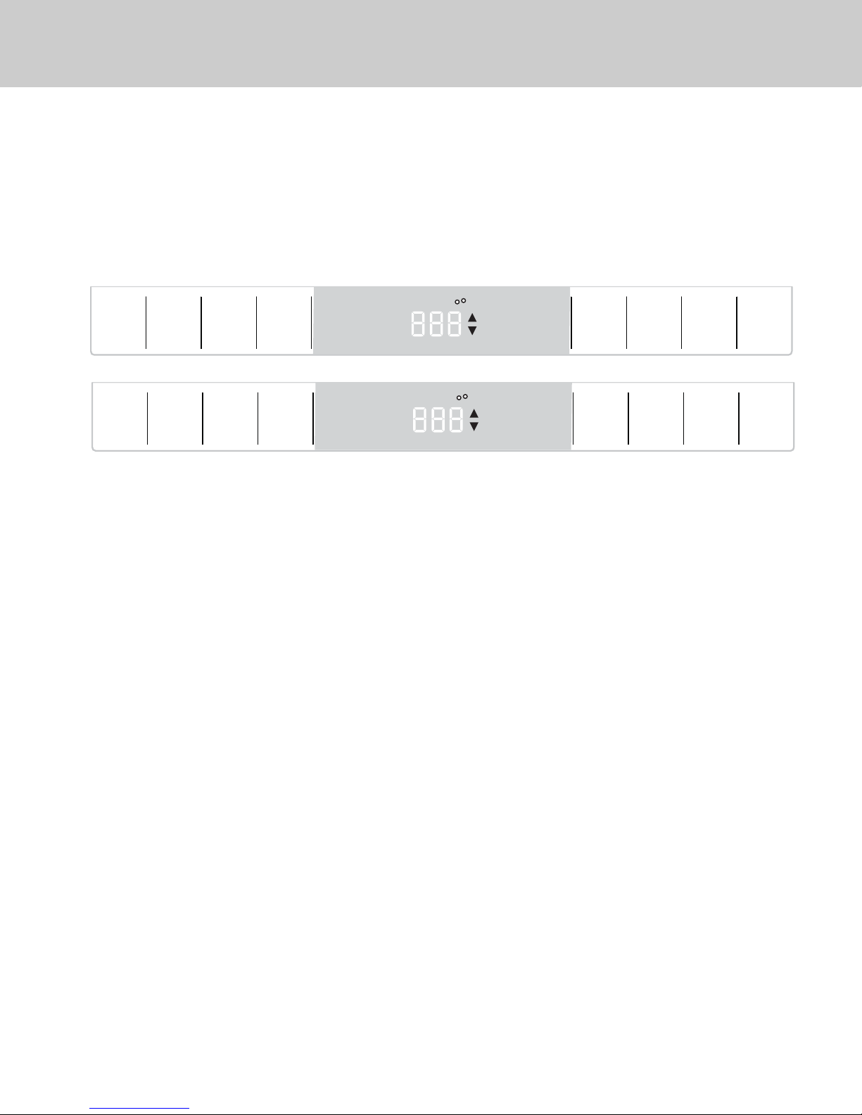
Verify Operations
44
Control Panels
1. Press “Activate Controls” pad.
2. Verify unit is not in Sabbath Mode.
If in Sabbath Mode:
A. The Sabbath Mode will disable the interior lights, display (except SAB indicator, temperature
and compartment indicator) and alarm.
To exit the Sabbath Mode:
B.. Press and hold “Activate Controls” and then “Display Off” for 3 seconds.
(The control will beep three times to alert the user the Sabbath Mode has been exited.)
3. Verify unit is not in Showroom Mode.
If in Showroom Mode:
A. The Showroom Mode will disable the refrigeration system but all other functions are normal.
These include lights and control. (If the refrigerator is in Showroom Mode, SHOW will be lit.)
To exit Showroom Mode:
B. Press and hold “Activate Controls”; while holding, press and hold “Higher” and “Alarm Off”
together. (The control will beep three times to alert the user that Showroom Mode has been
exited.)
4. Press “Activate Controls” then press and hold “Lower”; while holding, press and hold “Display Off”
and hold until beeps (force start compressor).
5. All models need to be set at 38° F and 0° F for the refrigerator and freezer respectfully - factory
setting.
All Refrigerator
All Freezer
ACTIVATE
CONTROLS
REF
TEMP
HIGHER LOWER
FREEZER
MAX FRZ MAX REF
FAST COOL
SAB SHOW
REFRIGERATOR
F
C
DOOR OPEN
POWER
HIGH TEMP
FAST
COOL
MAX
REF
ACTIVATE
CONTROLS
FRZ
TEMP
HIGHER LOWER
FREEZER
MAX FRZ MAX REF
FAST COOL
SAB SHOW
REFRIGERATOR
F
C
DOOR OPEN
POWER
HIGH TEMP
FAST
COOL
MAX
FRZ
ALARM
OFF
ALARM
OFF
DISPLAY
OFF
DISPLAY
OFF
Page 45

45
Service & Registration
Only authorized replacement parts may be
used in performing service on the appliance.
Do not repair or replace any part of the
appliance unless specifically recommended in
the manual. All other servicing should be
referred to a qualified technician.
Record the following information indicated
below. You will need it if service is ever required.
The serial number and model number for your
appliance are located on the identification plate
mounted behind the top light.
Model number
_________________________________________
Serial number
_________________________________________
Date of purchase
_________________________________________
Date installed
_________________________________________
Dealer's name
_________________________________________
Address
_________________________________________
Page 46

46
Page 47

47
Page 48
Viking Range, LLC
111 Front Street
Greenwood, Mississippi 38930 USA
(662) 455-1200
For product information,
call 1-888-(845-4641)
or visit our web site at brigade.ca
F21342 EN
(123113)
BRIGADE
TM
 Loading...