

Page 1
replica I
plus
Setup and Users Manual
JUNE 2014 PLUS EDITION
Briel Computers
Page 2

Replica 1 plus Users Manual
2
All materials, schematics, and hardware designs provided without any warranties. Although this material has been carefully examined,
Briel Computers takes no responsibility for any errors in printing.
Version 3.0
Published by Briel Computers
13465 Camino Canada Suite 106-114
El Cajon, CA 92021
USA
Copyright 2014 Briel Computers. All rights reserved. Printed in the United States of America. Except as permitted under the
Copyright Act of 1976, no part of this publication may be reproduced or distributed in any form or by any means, or stored in a
database or retrieval system, without the prior written permission of the publisher, with the exception that the program listings may be
entered, stored, and executed in a computer system, but they may not be reproduced for publication.
© Briel Computers 2014 page
Page 3

Replica 1 plus Users Manual
3
Forward
How the replica 1 came to be
Thank you for purchasing your replica 1 computer. I take pride in every kit and assembled replica that is
shipped and my goal is that all kits and assembled boards work as designed. In early 2001 I was an avid
collector of vintage computers. I had started with an Apple IIe because it was close to my first computer the
Apple II plus. I, like many people who get the urge to relive the vintage years of computing looked to eBay to
find my past. After receiving my first computer I found myself wanting a monitor, a disk drive, anything to
make it fully functional. I didn’t just want a mantle piece; I wanted to actually use my vintage machine.
After spending some time with my Apple I remembered other computers I had seen in magazines but couldn’t
afford at the time. I little searching and I was able to start a nice little collection of home computers. I was
addicted to vintage computing and collecting everything I could get my hands on.
I was really proud of the fact that every machine I owned, not only worked but I had software to run on them. I
was fast becoming an expert in the area of software conversion from the modern computer realm back to actual
vintage media like 5 ¼” disk.
Feeling proud that I had a nice collection going I stumbled upon the www.applefritter.com website. I felt pretty
versed with apple II hardware and I noticed a small forum there and poked in to read some of the posts. I didn’t
see anything out of the ordinary but I noticed a subject right above the Apple II section labeled Apple I. Well, I
had never seen an Apple I and had only herd the stories like most people about how Woz and Jobs started Apple
Computers from their garage. I had to read more.
I quickly learned that only about 50 Apple 1’s remained in existence from about 200 boards and they were
highly collectable and way out of my price range. I read a post where people talked about making a replica but
nobody was really stepping up to the plate. I have an education in engineering so I decided to take a look into
the Apple 1 hardware.
In March 2002 I wrote to the Applefritter forum requesting some information on the Apple 1 and I informed the
group of my intentions. I was well received and many former and current owners of Apple 1 computers gave me
information and documentation to get started.
With manuals and emails from owners in hand, I looked over every inch of the Apple 1. I quickly decided not to
use all the original components from the Apple 1 due to their lack of ability. Although there are chip suppliers
that carry surplus components, their prices and minimum orders are just out of the question. This left me with a
decision that many people questioned. I could have made the replica 1 look like the Apple 1 but in the spirit of
Woz, I choose to go with more modern components and reduce the chip count as low as possible.
I quickly found that I could interface 32K of RAM with no address decoding. Simply using Address line A15 as
the select line, I could activate the RAM chip with A15 off. So, if the replica 1 was looking anywhere in the
address range 0000-7FFF A15 would be low and RAM chip select activated. If the replica 1 was looking at
address range 8000-FFFF A15 would now be high and the RAM chip select would be deactivated. I added some
logic so that the access time of the RAM write cycle was only during PHI2 of the 6502’s clock. For this I used a
74LS00 NAND gate IC. I needed to invert the R/W signal and AND in PHI2. This required 2 of the 4 NAND
gates in the IC.
© Briel Computers 2014 page
Page 4

Replica 1 plus Users Manual
4
My next step was to add some address decoding so the replica 1 accessed the I/O chip 6821 PIA and ROM at
the same addresses the Apple 1 used. I used a 74LS138 to decode addressing for both the 6821 and an 8K
EEPROM. I also made sure that the space for BASIC (E000-EFFF) was EEPROM so BASIC could be stored in
ROM.
I now had a core CPU section replicated from the Apple 1. I still had no video section and I needed to build a
prototype. After some delays I finally built a prototype on wire-wrap and tested it. It didn’t work. I needed to
troubleshoot the board but my free time was very hard to come by and the replica sat on the shelf for a few
months.
In November of 2002 I received an email from Leander Kahney of Wired Magazine. He had been reading on
the replica project and wanted to interview me. My first reaction was, “Why me?” I had no idea the cult
following that Apple had. I really was fond of Apple since the beginning but Apple has such loyal owners and
they love everything that involves the history. So, here I am on the phone with Leander as he is asking me
questions about why I am doing the project, and when will it be completed and what will I be selling these for?
What? I didn’t have the heart to tell him that the project is on the self, that I have no idea what to sell these for
even if I had a working version. Little did Leander know that because of him, the replica 1 was pulled off the
shelf and completed. I started from scratch, and created a breadboard version of the replica 1. This time it
worked… Sort of… Well, the I/O chip, the 6821 was sending binary code for a “\” which means that the replica
was seeing a reset and the Woz monitor was trying to output a “\” to a TV monitor. Now I needed a video
solution.
Right after the Wired article was released, I received an email from Greg Glawitsch. He stated his interest in the
project and said that he had a “down and dirty” solution to the video problem. His answer was to use a
microcontroller to output TV text like the video terminal section of the manual. He offered to help by writing
the firmware to do this and it would only require a couple external IC’s to help the microcontroller. Wow, 3
chips to do what took about 24 on the Apple 1. This was perfect. And with some work with Greg, we had a
working video section.
In August 2003 the first of the replica prototypes were being made. I didn’t have a name for the board yet and
simply called it A1 replica. I also just put my initials on the board with the year 2003. Shortly after my first
prototypes were built, I created Briel Computers. At this stage my old high school friend Chris contacted Woz
through his webmaster asking for permission to use the Apple 1 code. His approval of the project prompted
another Wired article.
In October 2003, the first replica 1’s was being built and thus completing a 20 year old dream to design and sell
my very own computer. Thanks to Woz for being such a strong influence and great guy to give the ok for this
project.
Over ten years have now past and the replica 1 continues to evolve with new power supply connections,
different controller for video and other enhancements but the core machine is the same as it was from the
beginning.
Vince Briel
© Briel Computers 2014 page
Page 5

Replica 1 plus Users Manual
5
Setup and Users Manual
Index
Chapter 1: A Brief History of the Apple 1
Chapter 2: Introducing the replica 1 plus
Chapter 3: Unpacking and Setting Up
Chapter 4: Assembling Kit Version
Chapter 5: Programming the replica 1
Chapter 6: Using The USB to Serial Interface
Chapter 7: Using the Krusader Assembler
Chapter 8: Troubleshooting your replica 1
Appendix A: ASCII Keyboard Pin Out
Appendix B: Replica 1 Memory Map
Appendix C: Monitor Listing
© Briel Computers 2014 page
Page 6
Replica 1 plus Users Manual
6
Chapter 1: A brief History of the Apple 1
Steve Wozniak had designed and built many different little projects before the Apple 1 computer. The Apple 1
was not even his first computer design. He had designed the “cream soda computer” long before the Apple 1.
He had even designed a TV terminal that could be hooked up to a mainframe computer using a keyboard and
your TV as the display. Of course he also built the infamous “blue box” so people could phone phreak and
make free long distance calls. It wasn’t until Woz decided to combine two projects, and make one complete
computer never seen on the market before. He designed a single board computer and combined his TV terminal
to create what is today known as the Apple 1 Computer. He first presented the project to the Homebrew
Computer Club and it was well received. At that time, the only major computer out there was the Altair 8800
and that only came with LED’s and switches. The Apple 1 had a keyboard and a monitor. When he showed this
to his friend Steve Jobs, Jobs was excited and immediately wanted to make more to sell.
In April 1976, Steve Jobs and Steve Wozniak decided to start Apple Computer Company. It was based on a
computer design that Wozniak had completed making a computer that could display text on a TV and use a
keyboard without any additional boards. One board could do all of this. While it wasn’t the first home
computer, it was the first to give you all of these features on one board without any addition hardware. No
entering code by flipping switches and looking at LED’s. You could actually sit down at a table and type code
into the computer using a standard keyboard. Steve Jobs saw something great in this project and was eager to
start selling these boards.
Woz distributed schematics and source code listings for the Apple 1 computer at the Homebrew Computer Club
meetings in Northern California bay area. Steve Jobs knew that there was enough interest in the boards at the
Homebrew club to sell boards to the members. 200 boards were printed and most of them were assembled but
not all of them. They assembled boards at night in Job’s parents’ garage and sold some to the Homebrew Club.
It wasn’t until a local computer store purchased $50,000 worth of boards that anything significant had
happened. After that, things changed.
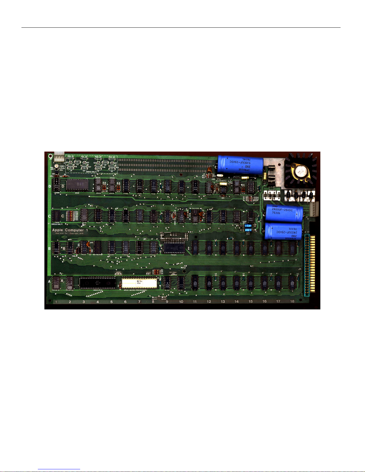
Figure 1: Actual Apple 1 Computer
© Briel Computers 2014 page
Page 7

Replica 1 plus Users Manual
7
They knew they had a great product and that the average person could have a computer on their kitchen table.
Woz quickly worked on a BAIC for the Apple 1 but it still lacked a means of storage. Shortly after the Apple
1’s release, Woz designed a cassette interface simply named the ACI (Apple Cassette Interface). This interface
allowed the user to store programs onto an audio tape using simple 1 and 2Kh signals to store the data.
While the new interface was being designed and BASIC was being written, the end of the Apple 1 was already
near. Woz was already working on the next version of his design. While many people thought the Apple II was
the same as the Apple 1 with just more features, the Apple II was a completely new design from scratch. This
new design could do color and using processor accessible RAM; you could do graphics and more. While this
was all being designed, the Apple 1 was still being made and sold.
BAIC was finally released and that gave the Apple 1 a high level language for people to program in. This BAIC
was not only written for the Apple 1, but it was also written for the Apple II at the same time. As a matter of
fact, if you look at a disassembly of the Apple 1 BAISC you will see some commands built in that are
impossible to perform, such as COLOR. There was no color graphics on the Apple 1, only text.
As soon as the Apple II was release, Jobs wanted to get rid of all the Apple 1 computers. He offered deals, like
half off an Apple II with the trade in of your old Apple 1. He so wanted to get rid of the Apple 1, that rumor has
it, he even gave some Apple II’s for even exchanges. Some he handed to engineers and programmers at Apple
to use, others he chopped up with a band saw. So, while there were 200 boards made from the board house, not
all were assembled and many were destroyed on the exchange program.
Today, approximately 50 Apple 1’s are known to exist making it one of the most sought after vintage
computers. Some auctions have fetched upwards of $50,000 for an Apple 1 but the average selling price is
around $150,000.
Figure 2: Steve Jobs and Steve Wozniak shown with an Apple 1 computer in 1976
© Briel Computers 2014 page
Page 8
Replica 1 plus Users Manual
8
Chapter 2: Introducing the replica I plus computer
The replica 1 computer was designed to give those people a chance to see what an Apple I computer looked and
acted like. Most people have never seen an Apple 1 running and the replica 1 helps us see what Woz had
created. The goal of the replica 1 project is to simulate the functional aspects of the Apple 1 so that all hardware
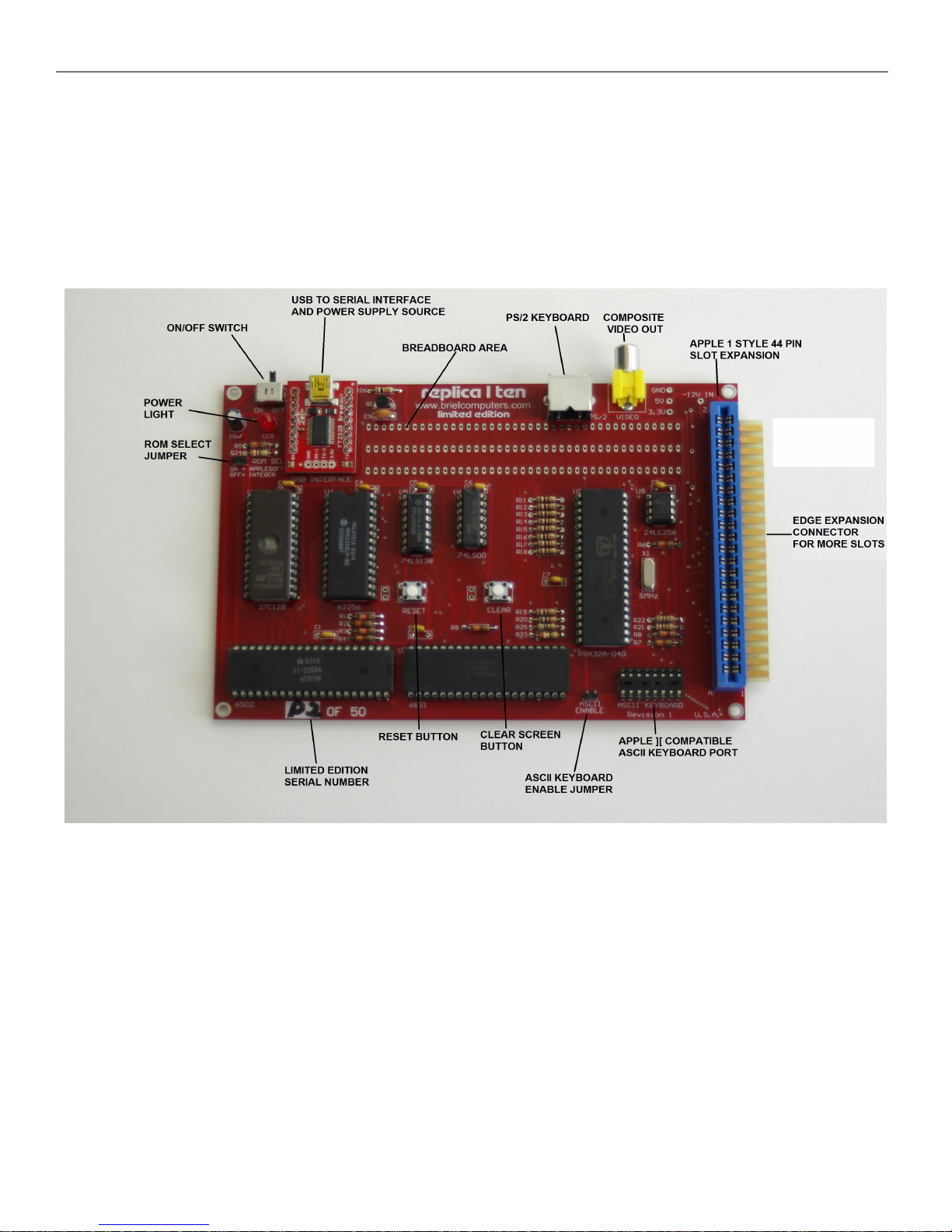
and software designed for the Apple 1 can be used. The plus is based on the limited edition tenth anniversary
edition shown below.
Figure 3: Key component features on the limited edition replica 1 ten
Not just a simple hobby board. The replica 1 contains features such as Apple 1 compatible expansion slot, and a
USB connection for power and serial to USB connection. The USB to serial port allows you to run a terminal
program on your Mac or PC and you can load and store programs to/from your PC to the replica 1. The USB
mini connector gives a modern standard so there is no more hunting for power supplies. Most USB power
supplies with at least 500mA will work great. We even offer a power supply and cable if you can't find one.
Firmware upgradeable: The replica 1 ten includes a Parallax Propeller micro-controller for the onboard I/O. The
source code is open source and is included with the replica 1 on the CD and updates can be made via free
software to program the Propeller from Parallax website. Programmers are welcome and encouraged to use the
Briel Computers forum to announce custom developed features and improvements to the firmware. The owner
takes all responsibility for any firmware installed that is not released or approved by Briel Computers. Using
untested firmware could damage the replica 1 plus, however with the Parallax software, restoring is easy.
© Briel Computers 2014 page
Page 9
Replica 1 plus Users Manual
9
The original 40 pin header that was offered on the previous versions of the replica 1 is now gone. It still remains
on the 3 slot expansion board for those who want to do their own hardware experiments.
As well as being able to run all the original Apple 1 software and hardware, the replica 1 has the capability to
use modern hardware like a ps/2 keyboard and use a standard USB connector power supply. The added USB
serial port gives the user the ability to download programs right from your PC or Mac into the replica 1 making
software sharing possible.
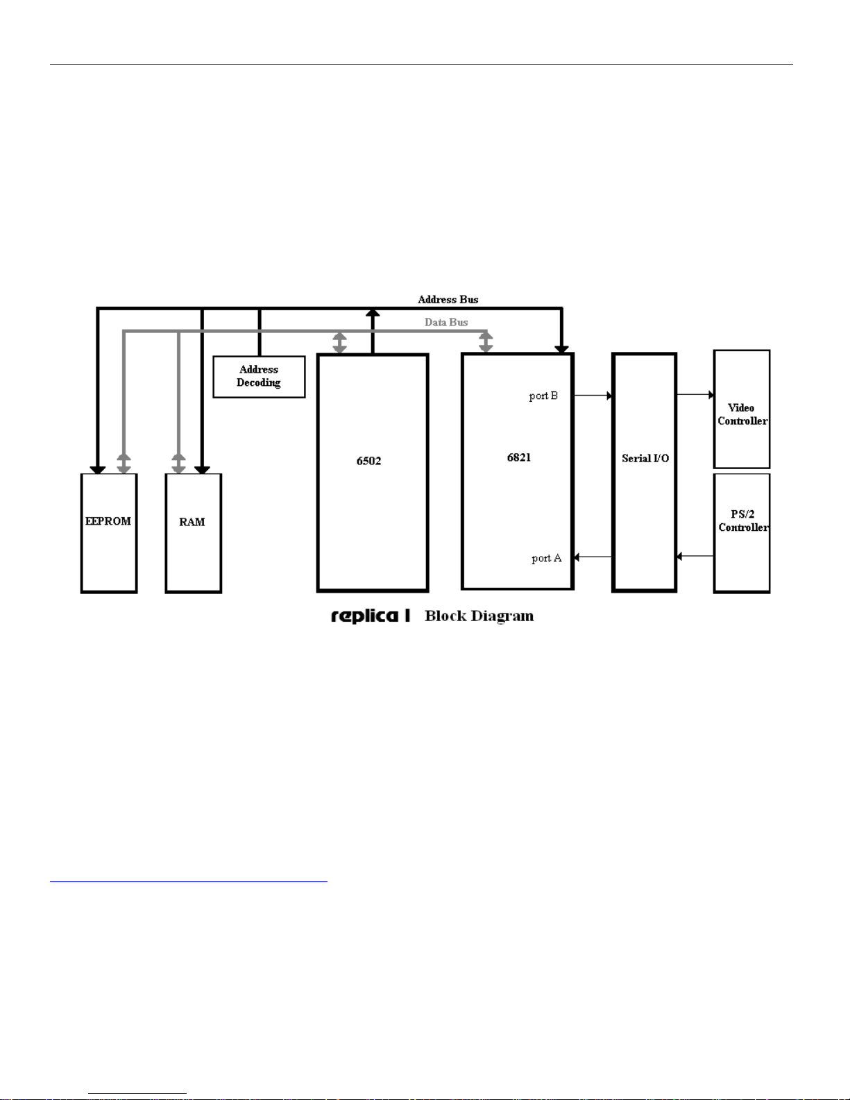
Figure 4: Logic diagram of replica 1 plus computer
Keeping a simple design structure was important with the replica 1. Chip reduction is the way Woz designed the
Apple 1 and the replica 1 follows in its path. Only 8 IC chips are now on the replica 1 plus the serial USB
adapter making it the most efficient replica 1 ever. The replica 1 ten continues uses the new Parallax Propeller
as the I/O controller plus it is now the master 1MHz clock and replaces 1 IC for logic. This new microcontroller has the ability to handle all I/O including video, serial, and PS/2 port.
While the replica 1 has been in production for over 10 years, it is always a work in progress. Sometimes bugs
and fixes come up and changes to the board are always discussed on the replica 1 forums. For the latest in
design changes and modifications, see the replica 1 forum at:
http://www.brielcomputers.com/phpBB2/
The replica 1 plus is currently the most advanced replica Apple 1 produced. It encompasses features as
requested by current or future owners of replica 1, as well as design improvements, bug fixes and other
enhancements. All revisions remain mostly backward compatible with the original replica 1.
© Briel Computers 2014 page
Page 10
Replica 1 plus Users Manual
10
Chapter 3: Unpacking and Setting up system.
Before you begin setting up your replica 1 computer, make sure you have plenty of table space. Do not power
up the unit while touching any part of the circuit board and contact Briel computers if you are unsure about any
part of the setup process.
You will need the following items to get your replica 1 up and running:
1. The replica 1 system board.
2. Mini USB connector to PC/Mac or power supply.
3. PS/2 PC style keyboard
4. A TV with composite video in, or a composite computer monitor.
5. A video cable to attach to the TV from the replica 1.
Place or mount the replica 1 board so that it is secured. Make sure no metal objects can touch the circuit board
or damage could result. Next you need to choose what type of power supply you are going to use. There are two
ways you can power your replica 1 plus. The mini USB cable is not only the serial port but also the power
source. If you intend on using the replica 1 ten just off your computer, you don't need a power supply. Try not
to use the replica 1 connected to a USB hub as the power requirements are different than a direct port.
Using a serial terminal program on your computer you can choose to use that as your keyboard and display if
you wish or connect a PS/2 or ASCII keyboard and video monitor.
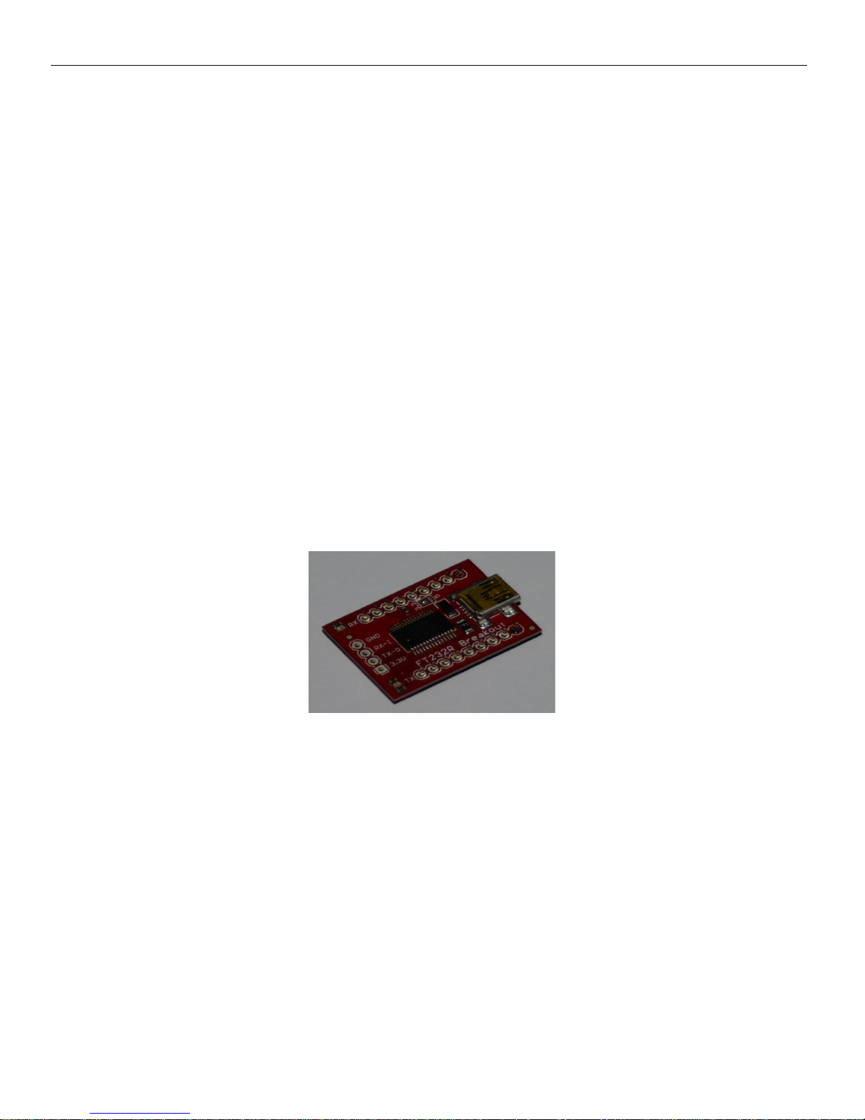
Figure 5: Mini USB connection for power and USB to serial port connection
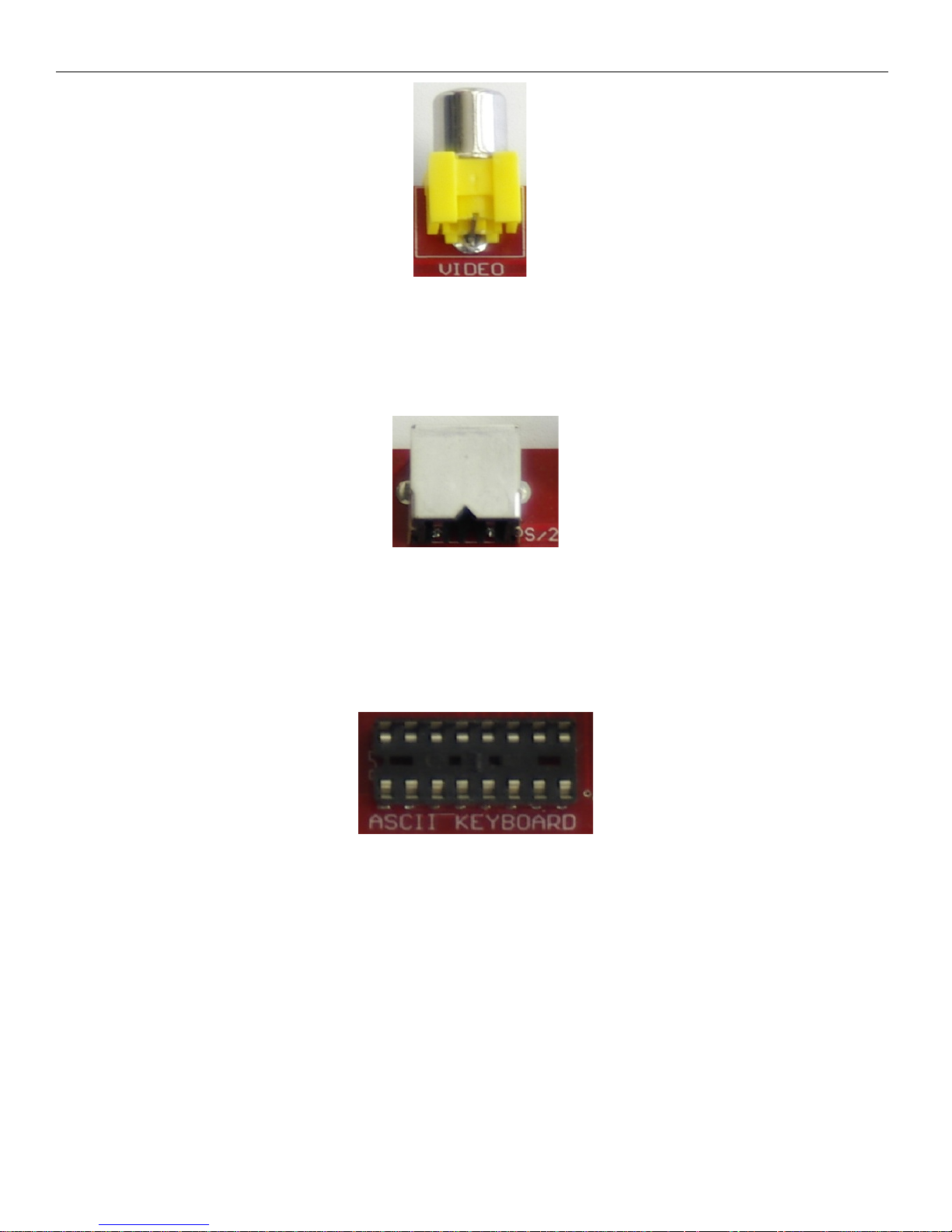
Once you have the power source connected, you can attach your monitor or TV to the replica 1 with a standard
composite video cable. Most modern TV’s have a composite input located on the back of the TV. Plug your
RCA style cable into the back of your TV or monitor and locate the video connector as shown and plug your
cable (not supplied) into the replica 1 (figure 6). The replica 1 ten was designed for NTSC but the driver is
listed as being PAL ready. We can provide a PAL version on the CD but can not test it at the moment.
© Briel Computers 2014 page
Page 11
Replica 1 plus Users Manual
11
Figure 6: Video connector
Next you need to attach a keyboard. You have two choices for keyboards; PS/2 PC style keyboard or an ASCII
keyboard. To use the PS/2 style keyboard locate the PS/2 port on the back edge of the replica 1 and plug your
keyboard into that port (see figure 7).
Figure 7: PS/2 keyboard port
If you are using an Apple 2 or 2+ ASCII keyboard, locate the ASCII keyboard port near the replica 1 logo on
the board and plug your 16pin dip cable into the board. Note that pin 1 is next to the ‘A’ on the ASCII
KEYBOARD label. Please note, you will need to supply your own -12V power for Apple II keyboards.
Figure 8: ASCII keyboard port
Now you are ready to test your replica 1 plus. Make sure your TV or monitor is turned on and flip the switch on
the replica 1 up. The red LED below the switch should light up and a screen of garbage should appear. If you do
not see the random garbage screen, or the LED is not lit, turn the replica 1 off and recheck your work.
Press RESET on the board and your replica will respond with a backslash “\” and the cursor will drop to the
next line. The cursor is a blinking ‘@’ symbol just like the original Apple 1 computer. You are now in the Woz
monitor and ready to use your replica 1 ten. If you are using the PS/2 style keyboard you will notice that the
caps lock is already on by default for you. The apple 1 only understands uppercase characters so does the
replica 1.
© Briel Computers 2014 page
Page 12

Replica 1 plus Users Manual
QUANTITY DESCRIPTION
1 6502 CPU
1 6821 PIA
1 27C128 EPROM
1 62256 SRAM
1 P8X32A-D40 PROPELLER
1 24LC256-I/P SERIAL EEPROM
1 74LS00
1 74LS138
1 5MHZ CRYSTAL
3 40 PIN MA CHINED SOCKETS
2 28 PIN MA CHINED SOCKETS
1 16 PIN MA CHINED SOCKETS
1 16 PIN DUEL SWIPE SOCKET
1 14 PIN MA CHINED SOCKETS
1 8 PIN MACHINED SOCKET
2 RESET & CLEAR BUTT ONS
2 100 OHM RESISTOR R21, R22
2 220 OHM RESISTORS R23,24
1 560 OHM RESISTOR R25
10 1K OHM RESISTORS R11-R20
9 3.3K OHM RESISTORS R1-R9
1 10K OHM RESISTOR R10
1 Q1 TRANSISTOR 2N4401
2 .01uF CAP C9 AND C10
8 .1uF CAPS C1-C8
1 10uF RADIAL CAP C11
1 RCA CONNECTOR YELLOW
1 44 PIN APPLE 1 SLOT
1 PS/2 KEYBOARD DIN CONNECTOR
1 RED L ED
1 ON/OFF SWITCH BUT DPDT
1 REPLICA 1 TEN LIM ITED EDITION PCB
2 9 PIN HEADER FT232 BREAKOUT
2 FT232 BREAKOUT BOARD USB
2 2 PIN HEADER
2 JUMPER SHUNTS
12
Chapter 4: Assembling the replica 1 plus kit
If you have experience with soldering circuit boards, then not only will you enjoy the replica 1 kit, but you will
also have the pride in assembling it yourself while saving money. If you have never built a circuit board kit,
please start with something a little simpler before attempting to build the replica 1. This chapter is only
designed as a brief guide to help you assemble your replica 1.
Kit contents:
© Briel Computers 2014 page
Page 13
Replica 1 plus Users Manual
13
Tools required for assembly:
Soldering iron, solder, wire cutters, needle nose pliers, and a multi-meter
Before you begin:
Make sure you have proper working space and that you heat your iron before beginning the assembly. This kit
is not for beginners and Briel Computers assumes that you have some prior experience with soldering circuit
boards. If you have never soldered circuit boards before or don’t feel you are ready, you should build other kits
of a smaller, less complex nature before building your replica 1.
Reading and identifying resistors:
In previous revisions of the replica 1 kits, all parts were labeled in an effort to make it easier on the kit builder.
Now, the manual is being expanded to help newcomers to kits learn to identify the parts and read their values.
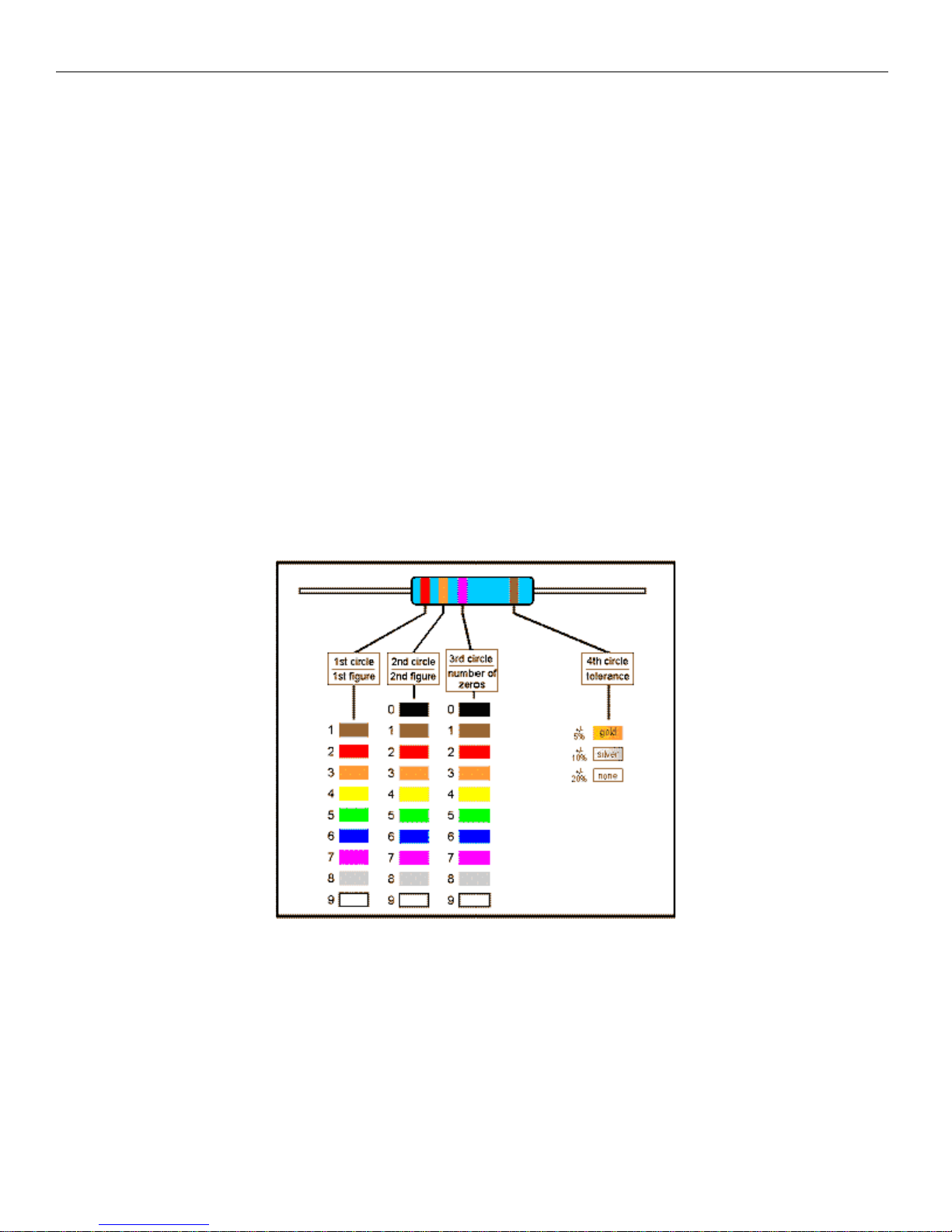
Resistors have 4 colored bands on them that are used to identify the value. The first 3 are the value and the 4th
colored band is to identify the tolerance of the resistor. The 4th band is usually silver for 10% or gold for 5%
tolerance. Here is how to read the other three to get the value:
Let’s assume the resistor you are trying to identify has the colors orange, and then another orange, then a red
band followed with a gold band. So, to read the resistor, find the gold or silver band, that identifies the 4th band.
Hold the resistor so the 4th band is on the right side and read the first color on the left.
The first color is orange which has a value of 3 according to the chart above. The second color is also orange
which also has a value of 3. The 3rd number indicates how many zeros follow the first two numbers. So, red is 2
zeros. This gives your resistor a value of 3, 3 and 2 0’s (00) or 3300=3.3K. This may take some practice but
look through all the resistors and identify them without a meter if you need practice.
Figure 9: Resistor color code chart
© Briel Computers 2014 page
Page 14
Replica 1 plus Users Manual
14
Reading and identifying capacitors:
It takes less time to read the values of the capacitors than to read the values of the resistors. The key is to
understand and read the numbers correctly.
Larger capacitors may have the values clearly printed on them. For example:
10uF = 10 Micro Farads
Smaller capacitors however, may only have 2 or 3 numbers on them. For example, the 22uF capacitors say
22J. .1uF capacitors have the value 104 on them. This is similar to the resistor codes where the first 2 numbers
are actual numbers and the 3rd number is the multiplier code. So 10 X 4 is 100,000 and the value is in pico
Farads (pF). Converting it to a proper numbering format gives us the value .1uF. To make things easier, here is
a list of the values on the capacitors used and the numbers printed on them.
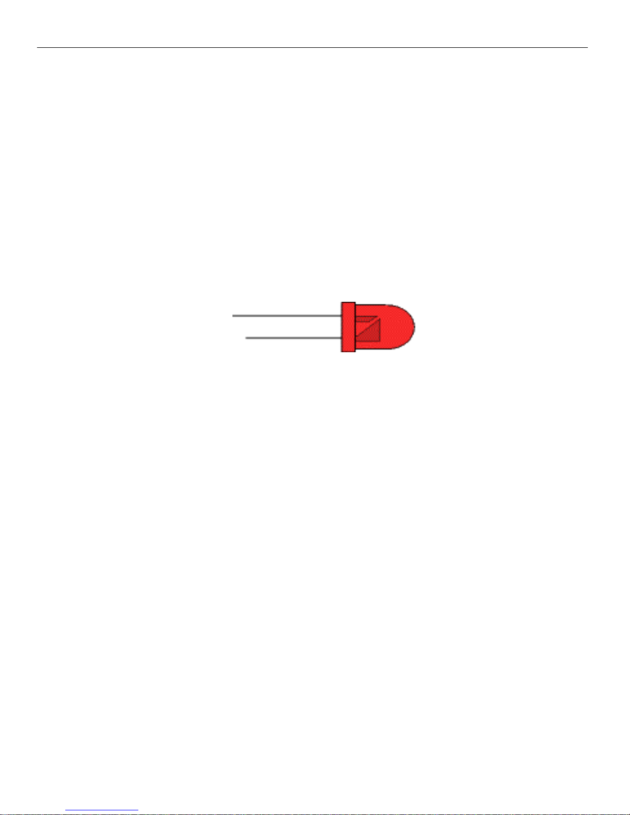
Power LED:
Figure 10: LED pin internal diagram
Looking at the LED there are two connectors, the Anode is longer and has the smaller connector inside. The
cathode is the negative side. It has a shorter lead and a larger part inside the LED. The cathode is the negative
post. Connecting is simple on the replica 1. The LED silkscreen on the replica 1 has the positive + marked.
Simply put the longer anode connector into the positive side when installing.
Ready to Begin Assembly:
Now that you have inventoried all parts you are ready to begin assembly of your replica 1.
Step 1: Start with the resistors. Bend the leads on each side of the resistor 90 degrees near the edge of the
resistor. Insert the resistor into its proper location until it rests flush with the board. They are not polarized so
that can be installed either direction. While holding the resistor with one finger, bend the pins on the bottom
side away from each other so that the resistor will not fall out and will stay flush on the board. Flip the board
over and solder the resistor down to the board. Cut the extra lead length off and throw away. Repeat for all
resistors carefully making sure each one goes in the proper location.
© Briel Computers 2014 page
Page 15
Replica 1 plus Users Manual
15
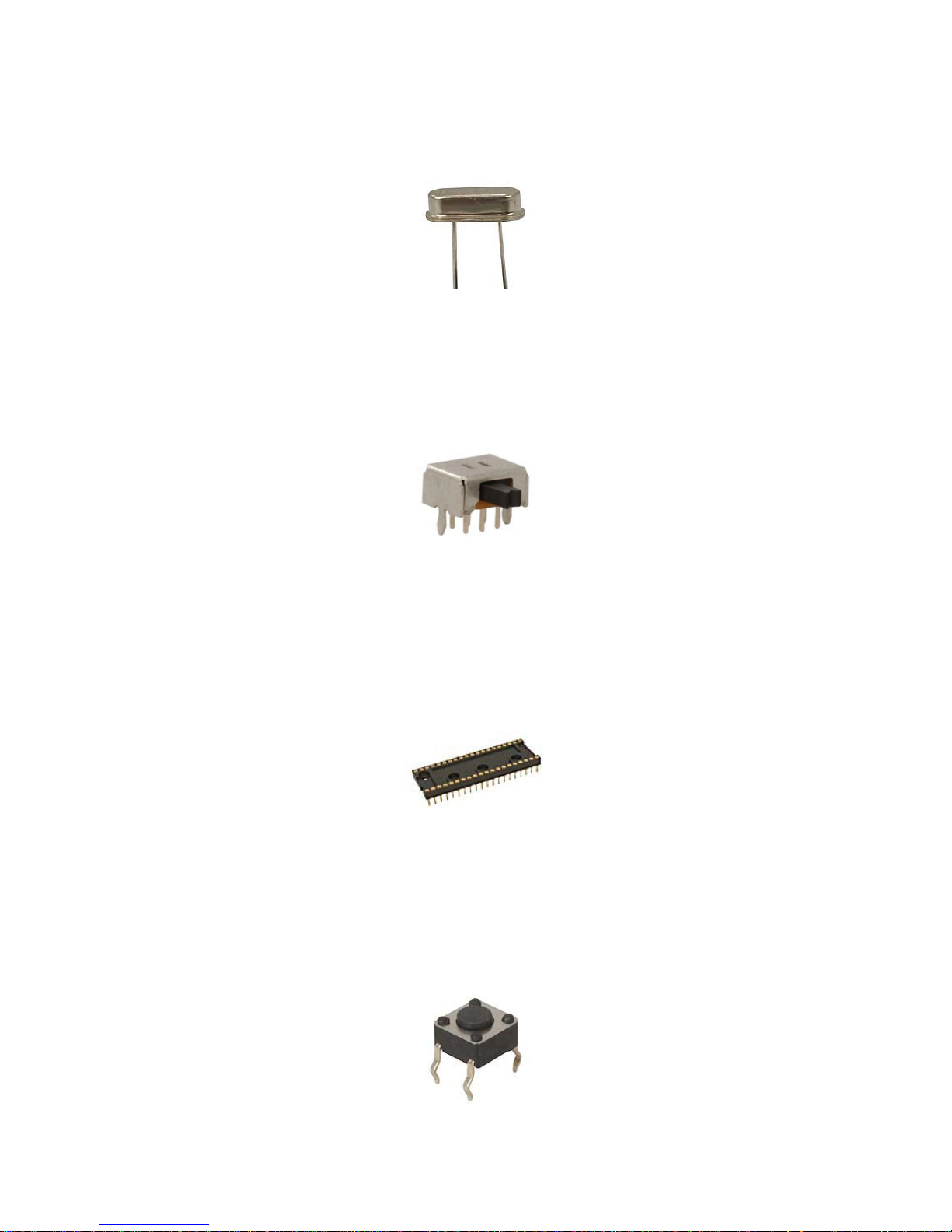
Step 2: Place the 5MHz crystal into its location and while holding it flush with the board, turn the board over
and set it on your work bench. Verify that the crystal is still flush with the board and solder the 2 pins into
place.
Figure 11: 5MHz crystal
Step 3: Insert the power switch so that the black switch portion sticks out off away from the board. Hold the
switch and turn over the board and place it on your workbench. Next carefully solder each pin down making
sure not to allow any solder to flow across to another pin. Check with a volt meter that no pins are touching.
Remember that some pins will contact because the switch is on or off.
Figure 12: Power switch
Step 4: Next is the sockets. I like to start with the largest sockets and work my way down. Insert the socket so
that the edge with the notch in it matches the board. If you get this wrong, it is ok, it is just a socket and does
not matter if it is installed backwards. I like to solder 1 corner pin and turn over the board and check to make
sure the socket is flush with the board. Once you check that, solder the remaining pins.
Figure 13: 40 pin socket
Step 5: Install the RESET and CLEAR buttons. You can fold the tabs to hold the buttons in place while you
turn the board over. Solder the pins in place and check your work. Sometimes they shift a little and need
adjusting.
Figure 14: RESET and CLEAR button
© Briel Computers 2014 page
Page 16
Replica 1 plus Users Manual
16
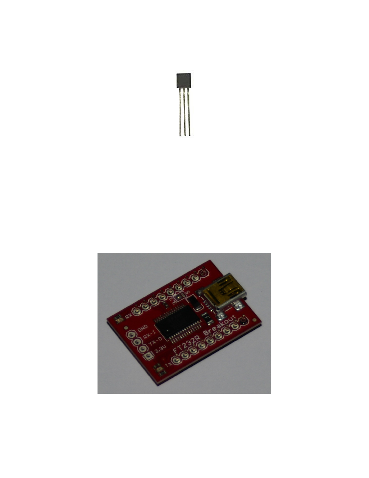
Step 6: Install the transistor. The pins may need to be separated a little to make them fit into the holes. Make
sure the flat spot on the transistor matches the flat spot on the board. Turn the board over and solder down. Cut
away the excess leads.
Figure 15: Transistor
Step 7: Installing the serial USB power interface. The small red USB board supplies power and serial to USB
communication with the replica 1 to a PC or Mac for data transfer. To install this board onto the replica 1, you
need to first install two 9 pin headers onto the USB interface. Push the pins through the bottom of the USB
board and rest it on the table with the pins on the bottom of the board. You have to be careful not to solder all
the pins right away or the spacing may be incorrect. Solder 1 pin on each of the two 9 pin headers. Make sure
the taller pins are pointed up through the USB board because you don't need a long lead through the replica 1
board. After you solder 1 pin each row, place the board and pins into the replica 1 board and adjust the headers
so they fit into the replica 1. Now that you have the spacing correct, while it is sitting in the replica 1 ten, solder
the remaining pins on the USB board. Hold the USB board still mounted in the replica 1 and turn the replica 1
over. Solder 1 pin of one of the 9 pin headers so the USB board is attached and check that everything is flush
before finishing up the remaining pins.
Figure 16: USB board
© Briel Computers 2014 page
Page 17
Replica 1 plus Users Manual
17
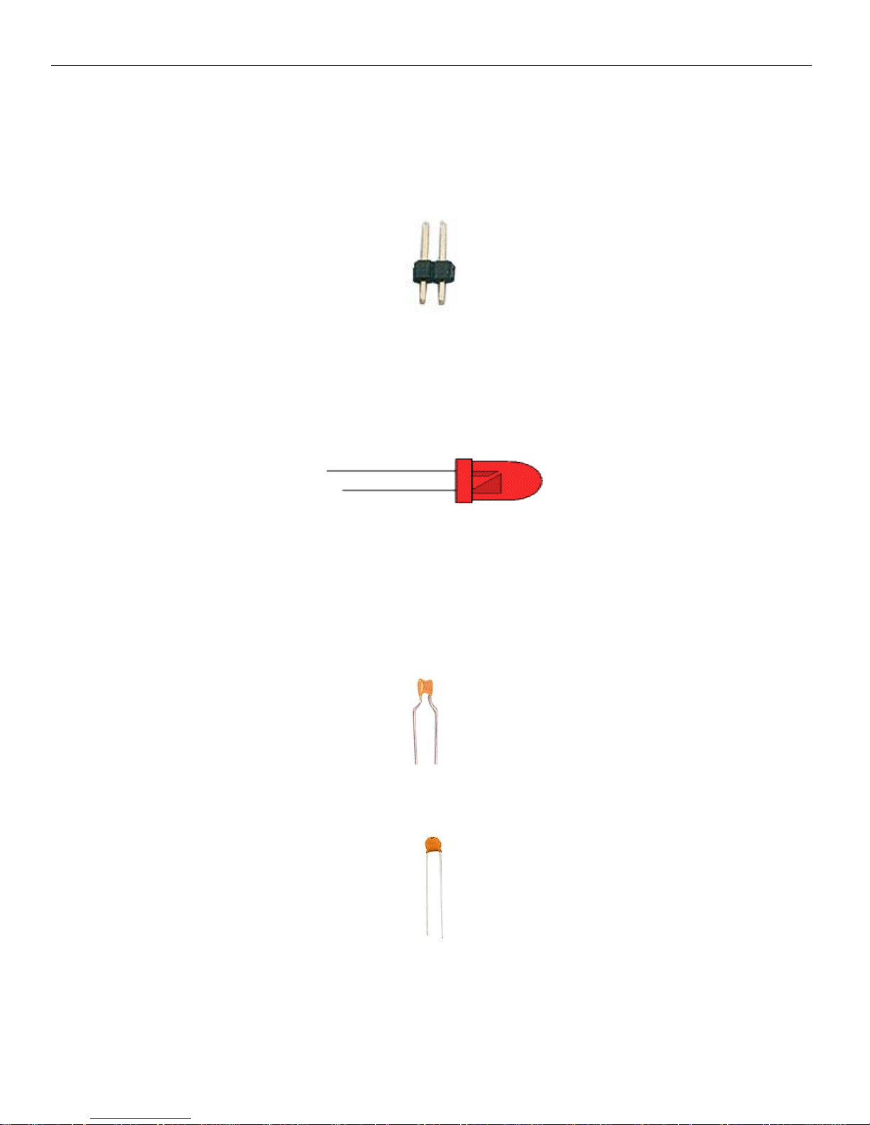
Step 8: Install 2 pin jumpers. Hold one jumper and install it near the EPROM. While holding the jumper, turn
over the replica 1 and place it on the work bench. Allow the work bench to hold the jumper while you solder
into position. You may need to adjust the replica 1 to make the jumper stand straight up before soldering.
Repeat this process for the jumper near the ASCII keyboard connector.
Figure 17: Jumper
Step 9: Install the LED into its location. The + lead is the longer lead. Make sure the LED goes all the way
flush with the board. You may have to wiggle the LED a little to get it all the way flush. Hold the LED into
position and turn the replica 1 over. Solder the LED pins and cut the extra length off.
Figure 18: LED light
Step 10: Install the 8 .1uF capacitors into the locations C1-C8. These capacitors are identified by 104 on the
them. These are not polarized so they can go in either direction. They vary by manufacturer so you may need to
adjust the pins to fit them into the board. I usually bend the pins away from one another to hold the capacitor in
place, then turn the board over and solder the pins. Cut the extra leads off.
Figure 19: .1uF capacitor
Step 11: Install the two .01uF capacitors like you did with the .1uF capacitors. ID is 103M on the caps. They
are not polarized so you can install them in either direction as well. Cut the extra length off.
Figure 20: .01uF capacitor
© Briel Computers 2014 page
Page 18
Replica 1 plus Users Manual
18
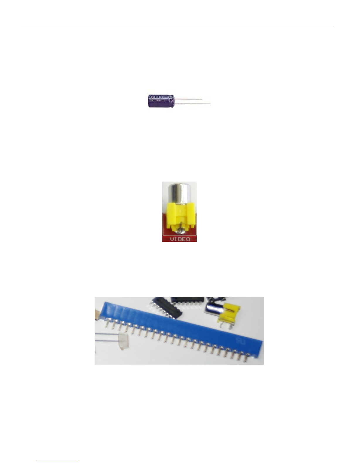
Step 12: Install the 10uF electrolytic capacitor. This capacitor is cylinder shaped and black. They are polarized
and the longer lead is the positive side. The negative side has an arrow pointing down to the lead to help out.
Place the capacitor so it is flush with the board. Bend the pins slightly away from one another to help hold the
position and turn the replica 1 over. Solder the 2 leads and cut the excess off.
Figure 21: 10uF electrolytic capacitor
Step 13: Install the video connector so that the round metal connector points out away from the board. Hold the
connector and turn the board over and place on your workbench. Solder the two pins down and use enough
solder to fill the holes completely.
Figure 22: video connector
Step 14: Install the 44 pin slot connector into its position. Notice that the socket may have identification of the
pin number on top of the socket. Look for the Z or the A and match it up with the board identification marks.
Hold the slot into position flush with the board and turn the replica 1 over. Solder 1 pin down and check that the
slot is flush with the board. Continue to solder the remaining pins until all 44 are soldered down.
Figure 23: 44 pin card slot
© Briel Computers 2014 page
Page 19

Replica 1 plus Users Manual
19
Step 15: Install the PS/2 keyboard connector. Use caution as the pins are fragile and the fit is very tight. The
supplier recently changed brands and the connection is a little different. We have gone to great lengths to get the
PS/2 holes corrected and matched up just right. Take your time and the connector will fit snug. Turn the replica
1 over and verify all pins have gone through the board. Solder the pins onto the replica 1.
Figure 24: PS/2 keyboard connector
Inspection of your work:
Now that you have completed your soldering, take a few minutes and look over your work. Check for solder
spots that might not be good connections to the posts. Look for bridges where solder may have jumped over
where it wasn’t supposed to go.
Testing your replica 1:
Before installing your IC’s, power up your replica 1. With your multi-meter, check the voltages 5V and GND.
make sure your LED is lit properly. Test 3.3V and ground. Test pin 14 and pin 7 on the 74LS00 to make sure
you are getting 5V. Check pin 8 and 16 on 74LS138 for 5V. Once you are satisfied that the power is being
distributed correctly, power off the replica. Install the P8X32A-D40 and 24LC256 EEPROM. Attach an RCA
cable to the replica 1 video port and attach it to your monitor or TV. Power up your replica 1 and see if you get
a screen full of garbage. If the video section is working properly, turn off the replica 1 and install the rest of the
chips. Power up the replica 1 again, this time press ‘RESET’ button after a couple of seconds and see if the
replica 1 resets.
If the circuit is working properly, you will get a “\” backslash followed by the cursor ‘@’ moving to the next
line. At this point you can power off the replica 1 once more and attach your keyboard. Power up the replica 1,
reset the circuit and try out the keyboard. Congratulations, your replica 1 is now assembled and ready to use.
Caution: Before plugging in the power supply, keyboard and video connector, thoroughly check
over your work for errors.
Any parts that get accidentally damaged during the building process can be replaced at the owner’s expense.
Contact Briel Computers for any replacement parts needed.
The goal of Briel Computers is that ALL replica 1 kits get completed successfully. If you are having a problem,
please feel free to ask for help.
© Briel Computers 2014 page
Page 20

Replica 1 plus Users Manual
20
Chapter 5: Programming the replica 1
The replica 1 can be programmed in one of 3 built in ways. You can enter values into memory directly using the
Woz monitor. Another way is to use BASIC that is built into ROM. BASIC was the most commonly used
language among beginner all the way to experienced programmers in the 70’s and 80’s. The third built in
way to program your replica 1 ten is to use the new Krusader© assembler written by Ken Wessen.
Using the Woz monitor:
The Woz monitor is a tool that gives you direct access to memory to program code that the 6502 will interpret.
To use the Woz monitor program, simply power up your replica 1. Just like the original Apple 1© you had to
manually reset the circuit to get the computer started. Simply press the reset button on the circuit board and you
will see a backslash ‘\’ and the cursor will drop below the backslash. You are now in the Woz monitor.
There are three basic functions to the Woz monitor. First, you can examine a range of memory or just one
location. To examine one location of memory, just type in the address and press [return]. To view memory
location 300 it would look like this:
300[RETURN]
0300: E1
The cursor will then move below the line that displayed the value of the memory location. To display a block of
memory, type in the starting location followed by a period ‘.’; follow that with the ending location. To view
300-32F locations, type:
300.32F[RETURN]
The replica will display the memory contents up to 8 locations per line:
0300: E1 20 94 17 08 26 60 10
0308: E4 98 02 86 88 44 A5 50
0310: 3C 2D 20 9D 7E 18 60 8C
0318: 0F 00 18 24 90 24 06 50
0320: 42 07 06 A0 89 81 00 C6
0328: 80 60 41 12 E0 1B A3 04
Again, the cursor will be below the listing.
To program a location in memory, simply type in the address followed by the value to write to it. For example,
to program location 300 with the value FF, simply type:
300:FF [RETURN]
The Woz monitor will respond by displaying the old value of the memory location:
0300:E1
© Briel Computers 2014 page
Page 21

Replica 1 plus Users Manual
21
The monitor will once again drop below the displayed line and be ready for more input. To program more than
one consecutive location simply put a space after the value, then type in the next value of the next memory
location. For example, to program 300 with FF, 301 with EE and 302 with DD type the following line:
300: FF EE DD [RETURN]
The monitor will respond with the prior contents of the first location you programmed (300):
0300:E1
If you examine the other two locations in memory, you will see the new value is now stored. Type:
301.302[RETURN]
The monitor then displays:
0301: EE DD
Notice it did not display 8 locations of memory across because you only asked for two. Once you have entered
your program into memory, you can start your program by entering the memory location that it starts at
followed by R for run and [return]. Let’s load and run a simple program through the Woz monitor. Type in the
following code:
300: A9 0 AA 20 EF FF E8 8A 4C 2 3 [RETURN]
Notice the ‘3’ and the ‘2’ are single digits, this is correct. You can type in ‘02’ or ‘00’ but it is not necessary.
After you have typed in the line, type:
300.30A
This will now print out the contents of the memory locations you just typed in. Verify the contents match the
code, then type:
300R [RETURN]
The program should then print out a continuous stream of characters. Every once in a while the screen will
clear; this is a normal function of the replica 1 having the ability to clear the screen through software.
© Briel Computers 2014 page
Page 22

Replica 1 plus Users Manual
22
Programming in BASIC:
To start the replica 1 and enter BASIC, turn on the replica and press reset. Next type in:
E000R [RETURN]
The memory contents of E000 are displayed and BASIC begins. The prompt for BASIC is ‘>’. This is how you
know you are in BASIC. Here is a simple ‘HELLO’ program you can type in:
10 PRINT “HELLO WORLD!”
20 END
RUN
When you type in RUN, the program will print out “HELLO WORLD!” onto the display, and then it will return
to the prompt. You can view your program by typing in “LIST”. To get started programming in BASIC, read
the BASIC manual. There are many example programs on the internet to help you get started.
Krusader:
The replica 1 has 8K of EEPROM (ROM) space onboard. 4K is used for BASIC; 256 bytes are used for the
Woz monitor. This leaves just under 4K available. Now, thanks to Ken Wessen, that space is now occupied with
a powerful assembler called Krusader. To start Krusader, type in ‘F000R’ [return]. To program the assembler,
refer to the Krusader manual for sample programs and commands.
Changing Boot ROMs:
Now that you have experienced the replica 1 like it was with the apple 1, you can use a new revised version of
Applesoft BASIC that was modified to work with the replica 1. Place the jumper on the ROM select with the
power switch in the off position. Turn on the replica 1 and press RESET like usual. The Woz monitor is still
there but when you enter E000R and press ENTER, the prompt is now a “]”. You are now in Applesoft lite.
Some features like graphics commands have been removed to make it fit in only 8K ROM.
© Briel Computers 2014 page
Page 23
Replica 1 plus Users Manual
23
Chapter 6: Using the USB to Serial Interface
With the previous versions of the replica 1, setting up the serial port was just a matter of setting up HyperTerminal which came with Windows. With more recent versions of Windows, Hyper-Terminal is no longer
included with Windows. We now will demonstrate how to set up a connection using Tera Term, a free terminal
emulation program. Connect your replica 1 to your PC/Mac with a USB cable. Turn the replica 1 and the driver
software should be found and installed automatically. Download and install Tera Term on your Windows
machine, you can use Zterm on a Mac.
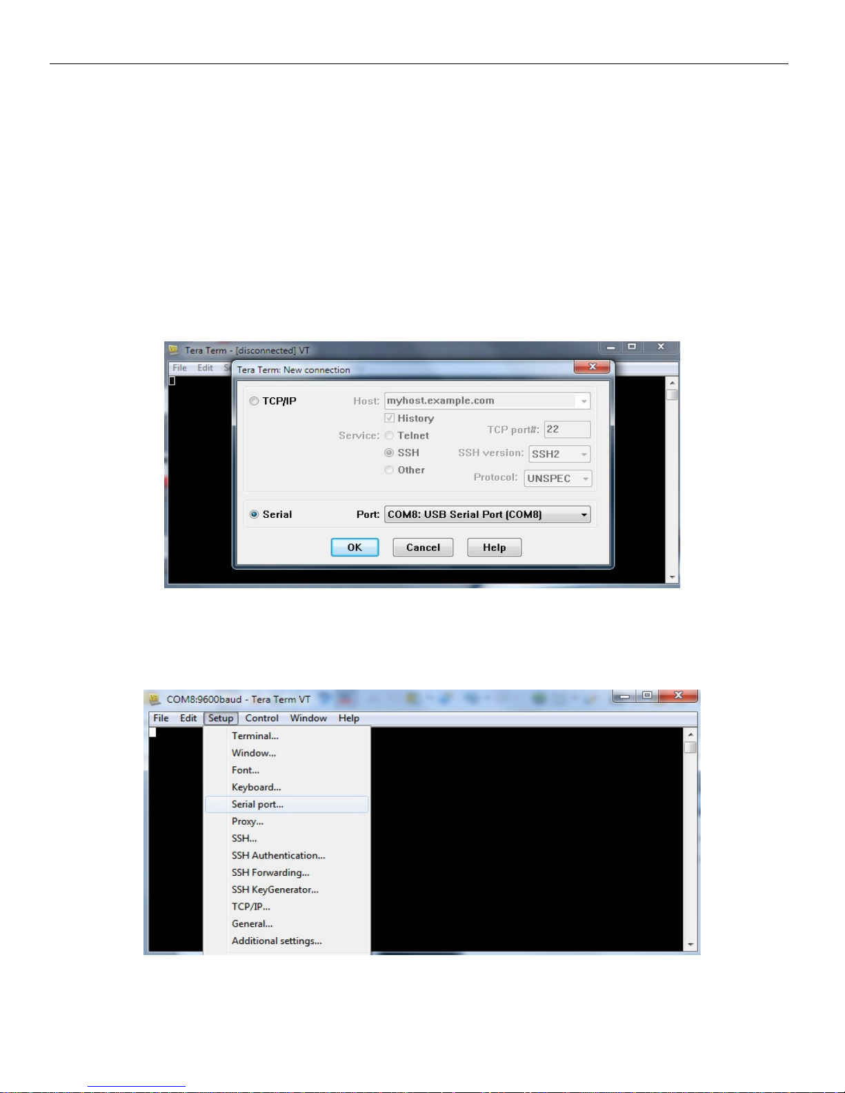
Once you have installed Tera Term on your system, start the program up. Change the default connection from
TCP/IP to Serial and select the new COMM port that should have installed when you connected the replica 1 to
your computer. See figure 11 for what your program should look like.
Figure 11: Setting up a new connection
Click on OK and your connection is started. You still have some settings to adjust before you can communicate
with the replica 1. Click on the Setup TAB and select Serial Port.
Figure 12: Accessing serial port settings
© Briel Computers 2014 page
Page 24
Replica 1 plus Users Manual
24
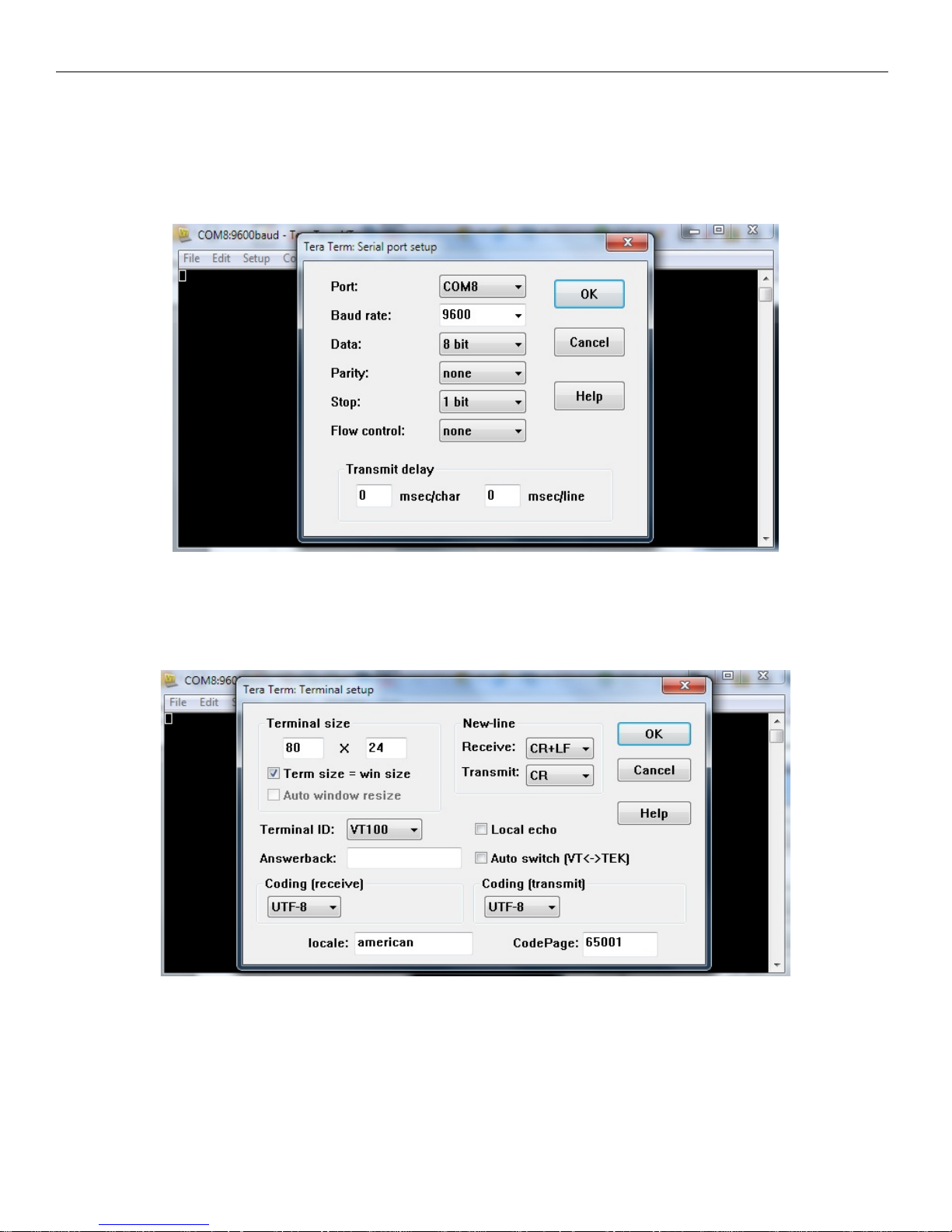
Under Serial Port options, the new BAUD rate for the replica 1 is the default 9600, 1 stop bit, no parity, and no
flow control. Change the msec/char from 0 to 50 and the msec/line to 200. This keeps proper delays so no data
loss should happen. Click OK to finish this section.
Figure 13: Serial Port Configuration window
Next click Setup again and this time select Terminal. On the terminal page, under New-line Receive: change the
value to CR+LF so a new line is created on ENTER. Click OK and you are ready.
Figure 14: Tera Term terminal setup screen
Press RESET on your replica 1 and make sure the CAPS LOCK is on your PC and type something and see if
what you type appears on the serial screen. If you have followed the steps correctly, you now have a connection
to your PC with the replica 1.
© Briel Computers 2014 page
Page 25
Replica 1 plus Users Manual
25
Transferring files with Tera Term
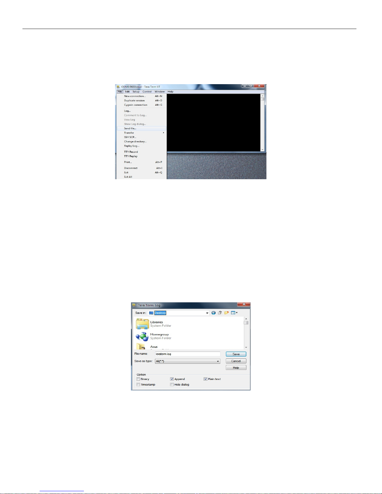
To send a file to your replica, simply click on the File tab, select “Transfer” then select “Send Text File” from
the drop down list.
Figure 18: Send text file
Find the file on your PC and select “OK”. At this point Tera Term will send the file your replica and your
replica will treat the file as if you were typing it in. Once it is finished typing in, just run your program as
normal. Remember, if you are sending a BASIC file to enter BASIC by typing “E000R” followed by “Enter”
before sending the file. Some files included will start for you automatically.
To receive a file is just as easy. Once again, click on the File tab, but this time select “Log” from the drop down
list. This will bring up a file name to save option and select the name for your file. Select “OK” to begin the
“Capture” mode. If you’re in BASIC you can type LIST and Hyper Terminal will capture your BASIC listing.
If you’re in the Woz monitor, simply type the address range to capture, followed by “Enter.”
Figure 19: Creating a log
© Briel Computers 2014 page
Page 26

Replica 1 plus Users Manual
26
Chapter 7: Using the Krusader Assembler
Krusader is a powerful assembler written by Ken Wessen for the replica 1. This assembler makes programming
the 6502 processor in the replica 1 a breeze. No hand converting mnemonic instructions to hex then manually
entering them in the Woz monitor. Now you can program using mnemonic instructions, assemble and run your
program right from the assembler. To enter the assembler, type in:
F000R [return]
The program will begin and the authors name and current revision will appear. Next line will display a ‘?’ with
the cursor next to it. Type ‘N’ to enter a new program. The assembler will now display ‘000’ for the first line.
Let’s enter the program listed in the Krusader as an example program.
000 is now displayed. Press space bar to skip the first field used for naming code blocks. The assembler tabs
over to the next field. Type LDA #’A’ [return];
001 is now displayed. Then type LOOP then press space bar to tab to the next field. Type JSR $FFEF
[return]. Type in the rest as shown:
002 CLC
003 ADC #$1
004 CMP #’Z’+1
005 BNE LOOP
006 RTS
Once you have entered in the source code, type L to list out the code, and then A to assemble it. To run your
code type R $300. The program will run and output the string:
ABCDEFGHIJKLMNOPQRSTUVWXYZ
Once the program finishes with the RTS command it will return to the Krusader assembler shell.
To learn more on how to program using Krusader, refer to the Krusader owner’s manual or visit the Krusader
web site at:
http://school.anhb.uwa.edu.au/personalpages/kwessen/apple1/Krusader.htm
© Briel Computers 2014 page
Page 27

Replica 1 plus Users Manual
27
Chapter 8: Troubleshooting your replica 1
If you have just built your replica 1 and are now having problems getting it running, here are some tips on what
to check:
Dead: Check jumpers to ensure correct setting for the type of power source you are using. Check your power
source to make sure it is functioning properly.
Replica 1 won’t reset: If you soldered from a kit, check for any points that didn’t get soldered. Check to make
sure all chips are seated properly. Make sure you soldered the oscillator in the correct orientation.
No response from the keyboard: Make sure you press reset before you begin using the replica 1. Check the
connector and be sure it is inserted properly.
Reset works but cursor stays on same line as backslash: This is an indication that communication between
the 6821 and the 6502 is not working correctly, or RAM is not functioning properly. If built from kit, check the
6821, 74LS04 and 62256 for missed soldering of pins. Make sure the chips are seated properly.
These are a few of the most common problems reported by kit builders. The number one source was missed
pins. If the pins don’t get soldered, the circuit may work, but act very strange. If you absolutely can’t find out
what is wrong, contact Briel Computers to have your board checked.
The replica 1 forums at: http://www.brielcomputers.com/phpBB2/ is a good source for information when
troubleshooting.
We want every kit that gets sold to operate properly so we will fix your kit for shipping charges plus cost on any
parts. Please contact Briel Computers at [email protected] before shipping in your board for repair.
© Briel Computers 2014 page
Page 28
Replica 1 plus Users Manual
28
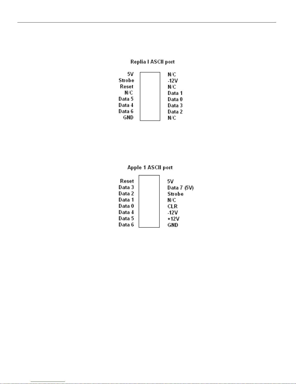
Appendix A: ASCII Keyboard pin out
Figure 20: replica I keyboard port from the 16 pin DIP connector. Pin 1 is 5V.
Figure 21: Apple 1 keyboard port from the 16 pin DIP connector; Pin 1 is reset.
© Briel Computers 2014 page
Page 29
Replica 1 plus Users Manual
29
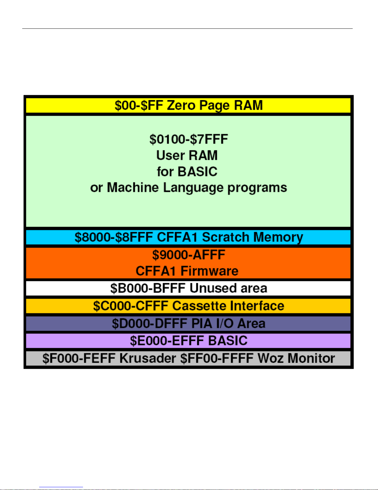
Appendix B: Replica 1 Memory Map
© Briel Computers 2014 page
Page 30

Replica 1 plus Users Manual
30
Appendix C: Woz Monitor listing
FF00: D8 RESET CLD Clear decimal arithmetic mode.
FF01: 58 CLI
FF02: A0 7F LDY #$7F Mask for DSP data direction register.
FF04: 8C 12 D0 STY DSP Set it up.
FF07: A9 A7 LDA #$A7 KBD and DSP control register mask.
FF09: 8D 11 D0 STA KBD CR Enable interrupts, set CA1, CB1, for
FF0C: 8D 13 D0 STA DSP CR positive edge sense/output mode.
FF0F: C9 DF NOTCR CMP #$DF “_”?
FF11: F0 13 BEQ BACKSPACE Yes.
FF13: C9 9B CMP #$9B ESC?
FF15: F0 03 BEQ ESCAPE Yes.
FF17: C8 INY Advance text index.
FF18: 10 0F BPL NEXTCHAR Auto ESC if > 127.
FF1A: A9 DC ESCAPE LDA #$DC “\”.
FF1C: 20 EF FF JSR ECHO Output it.
FF1F: A9 8D GETLINE LDA #$8D CR.
FF21: 20 EF FF JSR ECHO Output it.
FF24: A0 01 LDY #$01 Initialize text index.
FF26: 88 BACKSPACE DEY Back up text index.
FF27: 30 F6 BMI GETLINE Beyond start of line, reinitialize.
FF29: AD 11 D0 NEXTCHAR LDA KBD CR Key ready?
FF2C: 10 FB BPL NEXTCHAR Loop until ready.
FF2E: AD 10 D0 LDA KBD Load character. B7 should be ‘1’.
FF31: 99 00 02 STA IN,Y Add to text buffer.
FF34: 20 EF FF JSR ECHO Display character.
FF37: C9 8D CMP #$8D CR?
FF39: D0 D4 BNE NOTCR No.
FF3B: A0 FF LDY #$FF Reset text index.
FF3D: A9 00 LDA #$00 For XAM mode.
FF3F: AA TAX 0->X.
FF40: 0A SETSTOR ASL Leaves $7B if setting STOR mode.
FF41: 85 2B SETMODE STA MODE $00=XAM $7B=STOR $AE=BLOK XAM
FF43: C8 BLSKIP INY Advance text index.
FF44: B9 00 02 NEXT ITEM LDA IN,Y Get character.
FF47: C9 8D CMP #$8D CR?
FF49: F0 D4 BEQ GETLINE Yes, done this line.
FF4B: C9 AE CMP #$AE “.”?
FF4D: 90 F4 BCC BLSKIP Skip delimiter.
FF4F: F0 F0 BEQ GETLINE Yes. Set STOR mode.
FF51: C9 BA CMP #$BA “:”?
FF53: F0 EB BEQ SETSTOR Yes. Set STOR mode.
FF55: C9 D2 CMP #$D2 “R”?
FF57: F0 3B BEQ RUN Yes. Run user program.
FF59: 86 28 STX L $00-> L.
FF5B: 86 29 STX H and H.
FF5D: 84 2A STY YSAV Save Y for comparison.
© Briel Computers 2014 page
Page 31

Replica 1 plus Users Manual
31
FF5F: B9 00 02 NEXTHEX LDA IN,Y Get character for hex test.
FF62: 49 B0 EOR #$B0 Map digits to $0-9.
FF64: C9 0A CMP #$0A Digit?
FF66: 90 06 BCC DIG Yes.
FF68: 69 88 ADC #$88 Map letter “A”-“F” to $FA-FF.
FF6A: C9 FA CMP #$FA Hex letter?
FF6C: 90 11 BCC NOTHEX No, character not hex.
FF6E: 0A DIG ASL
FF6F: 0A ASL Hex digit to MSD of A.
FF70: 0A ASL
FF71: 0A ASL
FF72: A2 04 LDX #$04 Shift count.
FF74: 0A HEXSHIFT ASL Hex digit left, MSB to carry.
FF75: 26 28 ROL L Rotate into LSD.
FF77: 26 29 ROL H Rotate into MSD’s.
FF79: CA DEX Done 4 shifts?
FF7A: D0 F8 BNE HEXSHIFT No, loop.
FF7C: C8 INY Advance text index.
FF7D: D0 E0 BNE NEXTHEX Always taken. Check next char for hex.
FF7F: C4 2A NOTHEX CPY YSAV Check if L, H empty (no hex digits).
FF81: F0 97 BEQ ESCAPE Yes, generate ESC sequence.
FF83: 24 2B BIT MODE Test MODE byte.
FF85: 50 10 BVC NOTSTOR B6=0 STOR 1 for XAM & BLOCK XAM
FF87: A5 28 LDA L LSD’s of hex data.
FF89: 81 26 STA (STL,X) Store at current ‘store index’.
FF8B: E6 26 INC STL Increment store index.
FF8D: D0 B5 BNE NEXTITEM Get next item. (no carry).
FF8F: E6 27 INC STH Add carry to ‘store index’ high order.
FF91: 4C 44 FF TONEXTITEM JMP NEXTITEM Get next command item.
FF94: 6C 24 00 RUN JMP (XAML) Run at current XAM index.
FF97: 30 2B NOTSTOR BMI XAMNEXT B7=0 for XAM, 1 for BLOCK XAM.
FF99: A2 02 LDX #$02 Byte count.
FF9B: B5 27 SETADR LDA L-1,X Copy hex data to
FF9D: 95 25 STA STL-1,X ‘store index’.
FF9F: 95 23 STA XAML-1,X And to ‘XAM index’.
FFA1: CA DEX Next of 2 bytes.
FFA2: D0 F7 BNE SETADR Loop unless X=0.
FFA4: D0 14 NXTPRNT BNE PRDATA NE means no address to print.
FFA6: A9 8D LDA #$8D CR.
FFA8: 20 EF FF JSR ECHO Output it.
FFAB:A5 25 LDA XAMH ‘Examine index’ high-order byte.
FFAD: 20 DC FF JSR PRBYTE Output it in hex format.
FFB0: A5 24 LDA XAML Low-order ‘examine index’ byte.
FFB2: 20 DC FF JSR PRBYTE Output it in hex format.
FFB5: A9 BA LDA #$BA “:”.
FFB7: 20 EF FF JSR ECHO Output it.
FFBA:A9 A0 PRDATA LDA #$A0 Blank.
FFBC:20 EF FF JSR ECHO Output it.
FFBF: A1 24 LDA (XAML,X) Get data byte at ‘examine index’.
© Briel Computers 2014 page
Page 32

Replica 1 plus Users Manual
32
FFC1: 20 DC FF JSR PRBYTE Output it in hex format.
FFC4: 86 2B XAMNEXT STX MODE 0->MODE (XAM mode).
FFC7: A5 24 LDA XAML
FFC8: C5 28 CMP L Compare ‘examine index’ to hex data.
FFCA: A5 25 LDA XAMH
FFCC: E5 29 SBC H
FFCE:B0 C1 BCS TONEXTITEM Not less, so no more data to output.
FFD0: E6 24 INC XAML
FFD2: D0 02 BNE MOD8CHK Increment ‘examine index’.
FFD4: E6 25 INC XAMH
FFD6: A5 24 MOD8CHK LDA XAML Check low-order ‘examine index’ byte
FFD8: 29 07 AND #$07 For MOD 8=0
FFDA: 10 C8 BPL NXTPRNT Always taken.
FFDC: 48 PRBYTE PHA Save A for LSD.
FFDD: 4A LSR
FFDE:4A LSR
FFDF: 4A LSR MSD to LSD position.
FFE0: 4A LSR
FFE1: 20 E5 FF JSR PRHEX Output hex digit.
FFE4: 68 PLA Restore A.
FFE5: 29 0F PRHEX AND #$0F Mask LSD for hex print.
FFE7: 09 B0 ORA #$B0 Add “0”.
FFE9: C9 BA CMP #$BA Digit?
FFEB: 90 02 BCC ECHO Yes, output it.
FFED:69 06 ADC #$06 Add offset for letter.
FFEF: 2C 12 D0 ECHO BIT DSP DA bit (B7) cleared yet?
FFF2: 30 FB BMI ECHO No, wait for display.
FFF4: 8D 12 D0 STA DSP Output character. Sets DA.
FFF7: 60 RTS Return.
FFF8: 00 00 (unused)
FFFA: 00 0F (NMI)
FFFC: 00 FF (RESET)
FFFE: 00 00 (IRQ)
Page 0 Variables Other Variables
XAML 24 IN 200-27F
XAMH 25 KBD D010
STL 26 KBD CR D011
STH 27 DSP D012
L 28 DSP CR D013
H 29
YSAV 2A
MODE 2B
HARDWARE NOTES
© Briel Computers 2014 page
Page 33

Replica 1 plus Users Manual
33
Warranty
(Applies to factory assembled circuit boards only)
Briel Computers hereby warrants each of its products, and all components
therein contained, to be free from defects in materials and/or workmanship
for a period of thirty (3O) days from date of purchase. In the event of
the occurrence of malfunction or other indication of failure attributable
directly to faulty workmanship and/or material, then, upon return of the
product to Briel Computers, at 5392 Cornell Blvd, North Ridgeville, Ohio
44039 (postage prepaid), Briel Computers will, at its option, repair or
replace said products or components thereof, to whatever extent Briel
Computers shall deem necessary, to restore said product to proper
operating condition. All such repairs or replacements shall be rendered by
Briel Computers, without charge to the customer. The responsibility for
the failure of any Briel Computers product, or component thereof, which,
at the discretion of Briel Computers, shall have resulted either directly
or indirectly from accident, abuse, or misapplication of the product,
shall be assumed by the customer, and the Briel Computers shall assume no
liability as a consequence of such events under the terms of this
warranty. While every effort, on the part of Briel Computers, is made to
provide clear and accurate technical instruction on the use,
implementation, and application of its products, Briel Computers shall
assume no liability in events which may arise from the application of such
technical instruction, nor shall Briel Computers be held liable for the
quality, interconnection, or application of peripheral products, which may
have been recommended by Briel Computers, but which have not been supplied
as part of the product. This warranty contains and embodies the limits of
responsibility of Briel Computers, with regard to its products, and no
other liability is expressed, implied, or should be assumed by the
purchaser, and in no event shall Briel Computers be held liable for the
loss of time, effort, or transportation costs, nor for loss of potential
profits or other consequential losses which might arise from the purchase,
assembly, use, application, or subsequent sale of the products of Briel
Computers, nor from any instructions and/or technical information thereto
related.
© Briel Computers 2014 page
 Loading...