

Page 1
TM
* For pricing and a quotation, visit MeridianMicrowave.com
* For pricing and a quotation, visit MeridianMicrowave.com
GE/AR80 Installation Manual
making connections in a high-speed world
Wireless Gigabit Ethernet Links
Models GE80 and AR80
Installation Manual
580-00519, rev A 1 of 40
/N 580-00519
P
Revision A
September 2006
Page 2

TM
* For pricing and a quotation, visit MeridianMicrowave.com
* For pricing and a quotation, visit MeridianMicrowave.com
GE/AR80 Installation Manual
Copyright Notice & Disclaimer
Copyright © 2004-2006 BridgeWave Communications. All rights reserved.
inted in the USA
Pr
No portion of this publication may be reproduced, copied, or distributed without the
written consent of BridgeWave Communications. BridgeWave reserves the right to
update or change the material in this publication at any time without notice. BridgeWave
has made every effort to ensure that the information and the instructions contained in the
publication are adequate and is not responsible for any errors or omissions due to typing,
printing, or editing of this document.
Purchasers of BridgeWave products should make their own evaluation to determine the
suitability of each such product for their specific application. BridgeWave’s obligations
regarding the use or application of its products shall be limited to those commitments to
the purchaser set forth in its Standard Terms and Conditions of Sale for a delivered
product.
Customers are responsible for obtaining proper operator licenses.
This publication has been prepared for professional and properly trained personnel, and
the customer assumes full responsibility when using the information herein.
580-00519, rev A 2 of 40
Page 3

TM
* For pricing and a quotation, visit MeridianMicrowave.com
* For pricing and a quotation, visit MeridianMicrowave.com
GE/AR80 Installation Manual
Product Compatibility
While every effort has been made to verify operation of this product with many different
communications products and networks, BridgeWave makes no claim of compatibility
between its products and other vendors’ equipment. Customer is responsible for
thoroughly evaluated this product’s performance in the communications environment in
which it will be used.
Safety
CAUTION, WARNING, and DANGER statements have been placed in the text to alert
rsonnel of possible hazards. These statements must be closely observed.
pe
The following general safety precautions must be observed during all phases of operation
and service of the products covered in this manual. Failure to comply with these
precautions or with specific warnings elsewhere in this manual willfully violates
standards of design, manufacture, and intended use of the product. BridgeWave assumes
no liability for the customer’s failure to comply with these requirements.
• The GE/AR80 meets all applicable FCC safety requirements for radio equipment;
however, it is best to avoid prolonged, unnecessary exposure to the front of the
radio while it is operating
• The outdoor equipment must be properly grounded to provide some protection
against voltage surges and built-up static charges. In the event of a short circuit,
grounding reduces the risk of electrical shock.
For installations in the U.S.A., refer to Articles 810830 of the National Electrical
Code, ANSI/NFPA No. 70, for information with respect to proper grounding and
applicable lightning protection for DC cables.
For installations in all other countries, implement protection in accordance with
the safety standards and regulatory requirements of the country where the
equipment is to be installed.
• Do not install or operate this equipment in the presence of flammable gases or
fumes. Operation of any electrical instrument in such an environment constitutes
a definite safety hazard.
• Do not install substitute parts or perform any unauthorized modification to the
equipment. Changes or modifications not expressly approved by BridgeWave can
void the user’s authority to operate the equipment.
580-00519, rev A 3 of 40
Page 4

TM
* For pricing and a quotation, visit MeridianMicrowave.com
* For pricing and a quotation, visit MeridianMicrowave.com
GE/AR80 Installation Manual
Regulatory Information
This device complies with Part 101 of the FCC Rules.
Links installed in the U.S. must be registered with the FCC as provided for in Part
101 of the FCC regulations. For more information contact BridgeWave’s
Customer Service via E-mail [email protected]
or call at 408-567-6906.
Equipment Precautions
Water and Moisture - The GE/AR80 is designed to withstand precipitation conditions
typically encountered when installed outdoors.
Power Sources - This product should only be operated with the type of power supply
provided by BridgeWave Communications Inc.
580-00519, rev A 4 of 40
Page 5

TM
Copyright Notice & Disclaimer
2
* For pricing and a quotation, visit MeridianMicrowave.com
* For pricing and a quotation, visit MeridianMicrowave.com
GE/AR80 Installation Manual
Table of Contents
Section# Page #
Product Compatibility 3
Safety 3
Regulatory Information 4
Equipment Precautions 4
Table of Contents 5
1 Introduction
1.1 Purpose of Manual 6
1.2 Prior Knowledge and Manual Conventions 6
1.3 Contact Information & RMA 7
2 Site Planning
2.1 General 8
2.2 Equipment Checklist 8
2.3 Line of Sight 8
2.4 Link Distance 9
2.5 Antenna Location 9
2.6 Cabling 9
2.7 Grounding and Lightning Protection 12
2.8 Environmental 13
2.9 Simple Network Diagram 13
3 Installation
3.1 General 14
3.2 Equipment Packing and Unpacking 14
3.3 Equipment Inventory 15
3.4 Installation Tools 16
3.5 Antenna Mount Installation 17
3.6 Antenna and Radio Installation 20
3.7 Cable Installation 23
3.8
Turning the System On and Alignment 26
3.9 Auto Calibration 28
3.10 Test Cable 31
4 Operation of GE/AR80 & Configuration of Network
4.1 Configuring Network Equipment 34
4.2 Check port statistics 34
5 Troubleshooting
6 Distance vs. RSL Voltage
7 Standard Warranty Statement
6
8
14
33
35
37
38
580-00519, rev A 5 of 40
Page 6
TM
* For pricing and a quotation, visit MeridianMicrowave.com
* For pricing and a quotation, visit MeridianMicrowave.com
GE/AR80 Installation Manual
1 Introduction
1.1 Purpose of Manual
The information in this manual is directed to persons who must perform or coordinate the
sks associated with the process of installing wireless communication devices, and
ta
planning communication network applications.
1.2 Prior Knowledge
This manual assumes the operator has at least basic experience with and an understanding
of wireless technology and some familiarity with configuring and operating networking
equipment. Preferably, the person installing this equipment fully understands the
information covered in this manual prior to attempting these procedures.
DANGER! Indicates that personal injury can result if the user does not comply with
the given instruction. A DANGER statement will describe the potential hazard, its
possible consequences, and the steps to perform to avoid personal injury.
WARNING! Indicates that serious damage to the equipment can result if the user does
not comply with the given instruction. A WARNING statement will describe the
potential hazard, its possible consequences, and the steps to perform to avoid serious
equipment damage.
CAUTION! Indicates that equipment damage, process failure, and/or loss of data can
result if the user does not comply with the given instruction. A CAUTION statement will
describe the potential hazard, its possible consequences, and the steps to perform to avoid
equipment damage, process failure, and/or loss of data.
NOTE: Provides supplementary information to emphasize a point or procedure, or
provides a tip for easier operation.
580-00519, rev A 6 of 40
Page 7

TM
* For pricing and a quotation, visit MeridianMicrowave.com
* For pricing and a quotation, visit MeridianMicrowave.com
GE/AR80 Installation Manual
1.3 Contact Information
Technical Assistance and Customer Service
BridgeWave distributors and resellers are authorized local service providers and are
sponsible for immediate Tier 1 customer support. If problems are not resolved, contact
re
BridgeWave Customer Service for assistance:
Return Material Authorization (RMA)
Should BridgeWave equipment have to be returned for repair or replacement, an RMA
number must be obtained in advance from BridgeWave or a local BridgeWave
distributor. When returning equipment, be sure to write the RMA number on the outside
of the shipping carton.
580-00519, rev A 7 of 40
Page 8
TM
* For pricing and a quotation, visit MeridianMicrowave.com
* For pricing and a quotation, visit MeridianMicrowave.com
GE/AR80 Installation Manual
2 Site Planning
2.1 General
Before the start of an installation a survey should be conducted of the proposed area of
e deployment site(s). The survey personnel should be fully familiar with the details
th
required to install the GE/AR80 radio system.
2.2 Equipment Checklist
We suggest the site survey team may need the following equipment:
• Binoculars (not always required)
• GPS location device
• Tape measure to determine distances for cable runs to ingress points
• Digital camera (not always required)
• Site survey report form to document and help assess site
• Signaling mirror (provided and not always required)
• 70-90GHz Link Registration Datasheet. Contact BridgeWave Tech Support to
learn where one can obtain the latest version of this form. You may E-mail
for this request.
2.3 Line of Sight (LOS)
The GE/AR80 Wireless Gigabit Ethernet link requires LOS for proper operation.
Binoculars and spotting mirrors can be used to assist in confirming a LOS.
Path planning should include an investigation into future building plans that could block
the LOS path, and other long-term incremental obstructions such as tree growth.
Intermittent obstructions such as aircraft at a nearby airport should also be considered.
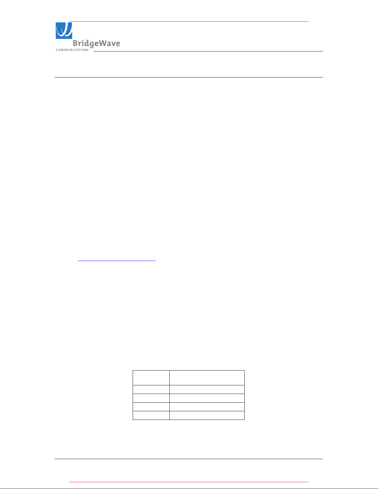
The following table details the minimum clearance needed from obstacles in order to
ensure the radios will operate properly.
Path Length
(meters)
1000 0.58
2000 0.82
5000 1.3
10000 1.8
Table 2-1: Minimum for Various Path Lengths
Minimum Clearance
(meters)
580-00519, rev A 8 of 40
Page 9

TM
* For pricing and a quotation, visit MeridianMicrowave.com
* For pricing and a quotation, visit MeridianMicrowave.com
GE/AR80 Installation Manual
2.4 Link Distance
Measurement of the link distance is important in estimating the link availability and
calculating expected Receive Signal Level (RSL). This measurement can be performed
using the Latitude and Longitude coordinate readings from a Global Positioning System
(GPS) device, which is placed near the proposed locations of the antennas. Additionally
GPS reading will be required in order to comply with the FCC registration process.
To quickly obtain estimated distances and availabilities for a given product and region,
use BridgeWave’s path calculator. To obtain the latest version of BridgeWave’s Path
calculator, contact BridgeWave’s Customer Service.
2.5 Antenna Location
The optimum location for the antennas must be determined. The ideal location should
ovide for ease of erecting and mounting the antenna, as well as providing unimpeded
pr
LOS to the remote location. The following factors should be taken into account:
• Type of mounting—fixed or roof-safe pole mounting
• Location where the fiber and DC power wiring will enter/exit the building
• Length of cable runs
• Grounding connection points
• Obstructions, including allowances for tree growth
• Accessibility of mounting location
• Access to building after regular working hours
2.6 Cabling
The installation site should be inspected to determine the run paths for the fiber cable and
wer cable from the radio equipment to the termination point. Locations for roof
po
penetration should be identified. The routing and securing of all cables should conform to
all applicable codes and requirements. Depending on the likelihood of damage due to foot
traffic or equipment movement, cabling conduit may be required. The maximum cable
run length as specified for the equipment being installed must not be exceeded.
580-00519, rev A 9 of 40
Page 10
TM
* For pricing and a quotation, visit MeridianMicrowave.com
* For pricing and a quotation, visit MeridianMicrowave.com
GE/AR80 Installation Manual
The radio requires LC type connectors on a pair of simplex multi-mode fibers to properly
connect between the radio and the users network equipment. Single-mode fiber
connections are not supported for use with the standard product. The network equipment
end of the fibers should be terminated with connectors that match the user’s network
equipment fiber interface.
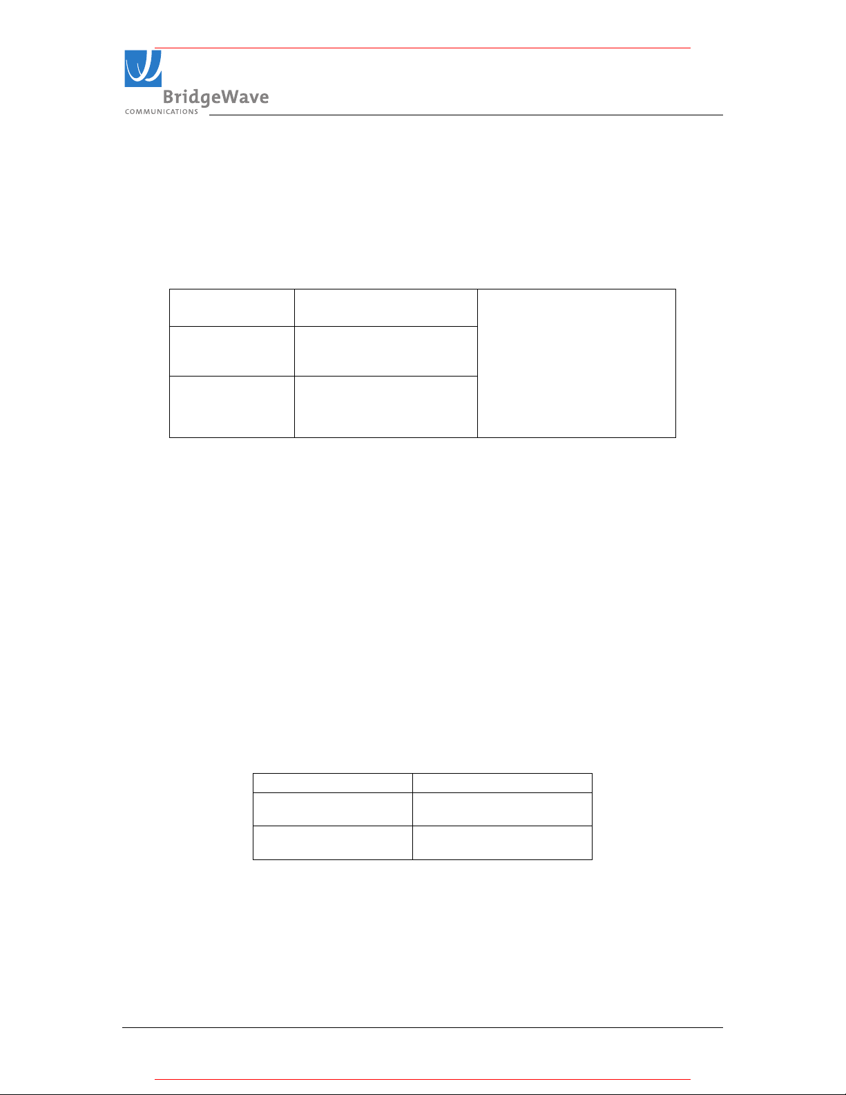
Cable Type
Up to 270 meters 62.5/125 µm
Up to 500 meters 50/125 µm
Table 2-2: Fiber Cables with LC Type connectors
The GE/AR80 radio includes a 100-240 VAC power adaptor suitable for indoor operation
only that converts the AC voltage from a standard electrical outlet in the wall to DC
voltage. The radio requires a minimum of 15.0 VDC at the connector on the radio unit
(24.0 VDC maximum) to function properly. When planning the cable run from the indoor
AC power adaptor to the radio unit, it is required to use the cable gauge (AWG) indicated
below to ensure adequate voltage at the radio. The indoor and outdoor portions of the
DC power cabling must conform to all respective indoor and outdoor national and local
electrical and building codes; note that requirements may differ for the indoor and
outdoor portions of the cabling and that a grounded surge protector is normally required
at the point where the cable enters the building. The DC power cabling must consist of
two 12 or 14 gauge conductors based on the required cable run length.
Minimum Cable Size
Cable Length Conductor size
DC
14 AWG
Up to 125 meters
Up to 200 meters
Table 2-3: Minimum DC Cable Size
580-00519, rev A 10 of 40
(2.5mm2)
12 AWG
(4mm2)
Page 11

TM
* For pricing and a quotation, visit MeridianMicrowave.com
* For pricing and a quotation, visit MeridianMicrowave.com
GE/AR80 Installation Manual
Figure 2-4: 14-gauge DC power cable terminated to radio end and power supply end.
Figure 2-4 (right) details a standard 14-gauge wire that has been fitted with the power
connectors (provided) for the radio’s internal power supply necessary to mate with the
(not provided) power cord. A standard crimping/splicing tool (not provided) is required
to terminate the power connectors onto a 14-12-gauge cable required for use with the
GE/AR80.
On the radio end (left) no connectors are required; simply screw terminals to appropriate
polarity.
580-00519, rev A 11 of 40
Page 12
TM
* For pricing and a quotation, visit MeridianMicrowave.com
* For pricing and a quotation, visit MeridianMicrowave.com
GE/AR80 Installation Manual
2.7 Grounding & Lightning Protection
WARNING!
Proper grounding of the outdoor equipment reduces electromagnetic interference,
provides surge protection, and protects against electrical discharge. The source and
connection points for the building-to-earth ground in the vicinity of the antenna location
should be determined.
It is recommended to connect the radio to the building ground by connecting the building
ground to the conductive pole mount hardware structure. For wall or ungrounded pole
mounts, connect a grounding wire to the grounding point on the radio. Select the size of
the ground wire based on the National Electrical Code.
In addition to grounding the equipment, BridgeWave strongly recommends, and local
building codes may require, the DC electrical cable to be protected from electrical surges.
You should use a Polyphaser surge suppressor, model # IS-PSP-24 or equivalent (not
provided). The surge suppressor must be installed at the point where the DC electrical
cables exit/enter the building.
The Polyphaser device is available from the following companies:
Hutton Communications 877-648-8866 www.huttoncom.com
TESSCO Technologies 800-472-7373 www.tessco.com
Winncom Technologies Corp. 888-946-6266 www.winncom.com
580-00519, rev A 12 of 40
Page 13
TM
* For pricing and a quotation, visit MeridianMicrowave.com
* For pricing and a quotation, visit MeridianMicrowave.com
GE/AR80 Installation Manual
2.8 Environmental
The structure to which the equipment will be mounted should be adequate to bear all
nd and weather conditions. The environmental conditions at the location must conform
wi
to the operating environment specified for the equipment.
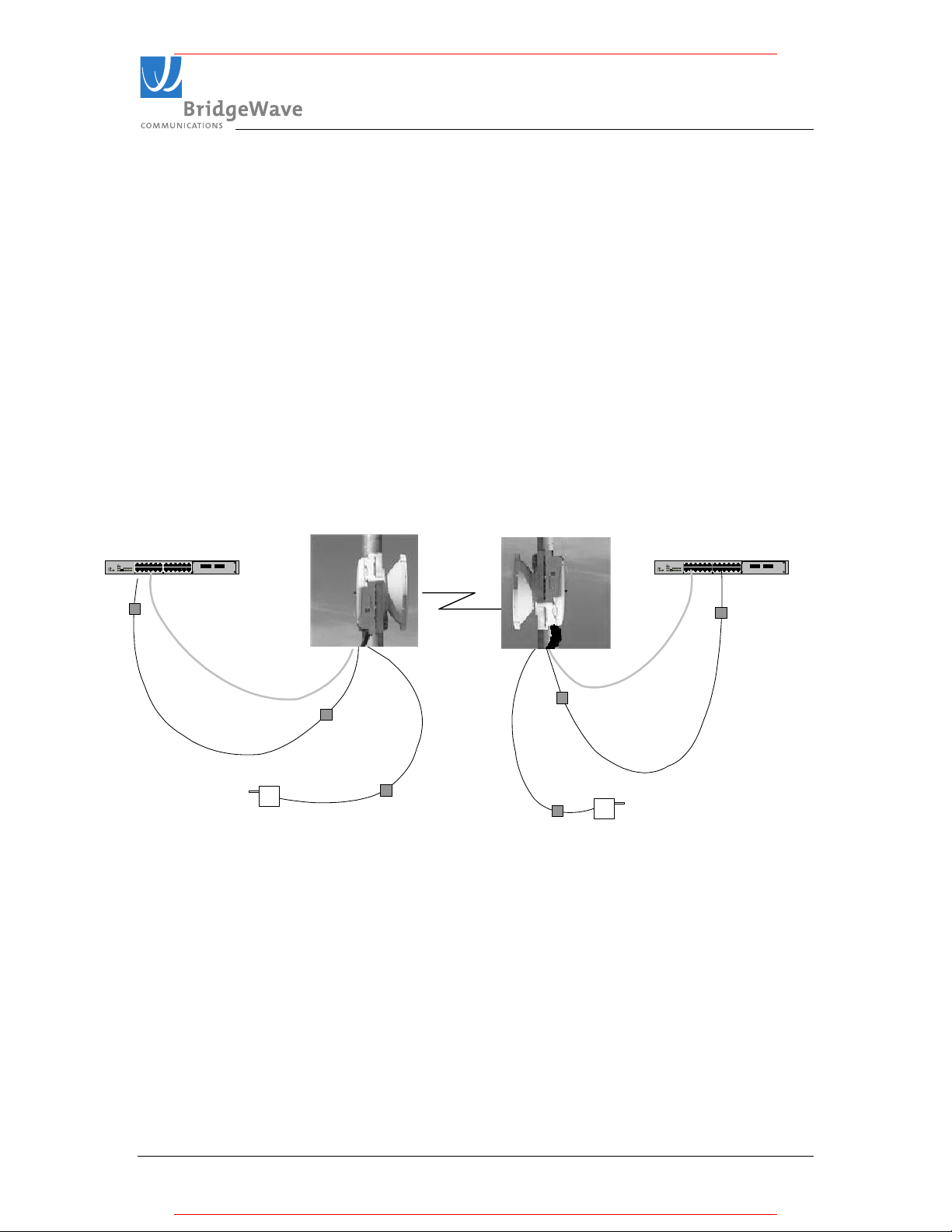
2.9 Simple Network Diagram
Following is a diagram detailing the equipment and cabling found on a typical
installation of BridgeWave’s 80GHz radio equipment.
C
78 9 101112
Ethernet
12 3 45 6
A
Gig-E Switch or
Router
12x6x8x2x9x3x10x4x11x5x7x
1x
1x
B
A
Surge Supressor
Cat5 Cable (Optional)
Indoor
Power
Supply
High-Band Radio
Vertical Polarization
12x6x8x2x9x3x10x4x11x5x7x
Path
between
radios
Fiber Optic Cable
Surge Supressor
(inside housing)
DC Power
Cable
Surge Supressor
Low-Band Radio
Vertical Polarization
DC Power
Cable
Surge Supressor
Fiber Optic Cable
Surge Supressor
(inside housing)
Cat5 Cable (Optional)
Indoor
Power
Supply
C
78 9101112
Ethernet
12 3 4 5 6
A
Gig-E Switch or
Router
12x6x8x2x9x3x10x4x11x5x7x
1x
1x
B
A
Surge Supressor
12x6x8x2x9x3x10x4x11x5x7x
Figure 2-5: Simple Network Diagram
580-00519, rev A 13 of 40
Page 14

TM
* For pricing and a quotation, visit MeridianMicrowave.com
* For pricing and a quotation, visit MeridianMicrowave.com
GE/AR80 Installation Manual
3 Installation
3.1 General
It is recommended that installation personnel read this section in its entirety prior to
stalling the BridgeWave System. During a particular phase of installation, the user may
in
refer directly to the applicable subsection.
The Installation section is comprised of seven subsections covering the procedures and
guidelines for installing the BridgeWave Radio System.
Subsections 3 through 3.4 contain information necessary to prepare for the equipment
installation.
Subsection 3.5 through 3.7 covers equipment installation procedures.
Subsection 3.8 contains information necessary for aligning the antenna.
3.2 Equipment Packing & Unpacking
The radio system equipment will arrive in two boxes—one box for the low band radio
and one box for the high band radio. Locate the correct box (low band or high band)
before beginning installation by checking the label on the outside of the box or on the
radio itself. It is recommended that the shipping cartons and packing materials be
retained in the event that it is necessary to return any equipment.
Note: The polarity can be identified on unpacked radios by the first letter of the polarity
V or H (Vertical or Horizontal) on the top of the unit chassis. See Figure 3-8 for further
details.
580-00519, rev A 14 of 40
Page 15
TM
* For pricing and a quotation, visit MeridianMicrowave.com
* For pricing and a quotation, visit MeridianMicrowave.com
GE/AR80 Installation Manual
3.3 Equipment Inventory
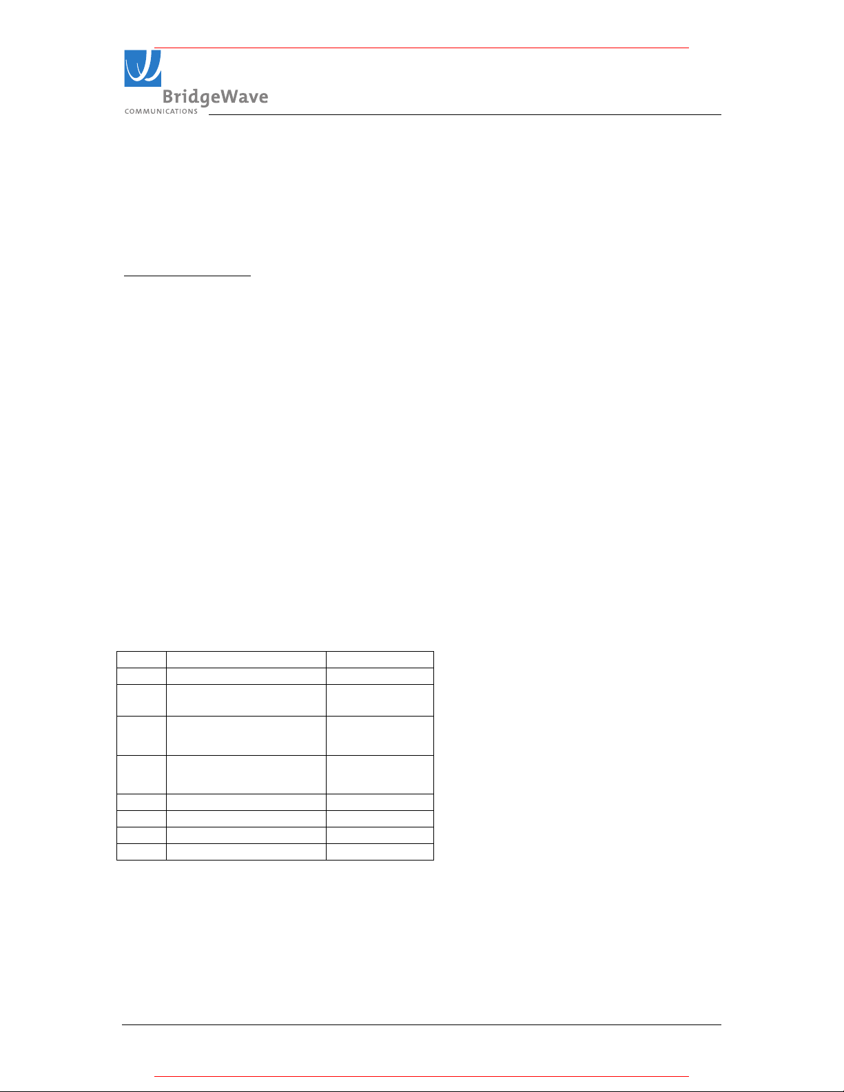
Following are inventory lists for a typical system:
Qty Description
2 ea. GE80 radio units (1 low band transmit unit & 1 high band transmit unit)
2 ea. AC-DC power adapters & power cords
1 ea. CD-ROM containing Installation Manual and NMS Manual (1 CD provided per
pair of radios)
2 ea. DC power connectors for use with outdoor radio
4 ea. DC power connectors
2 ea Antenna and mount kits
1 ea. Sighting mirror
, 3" X 5"
1 ea. Hard reset box
2 ea. RSL and Quality voltage test cables
2 ea. Stainless Steel Screws # 8-32 X 3/8, Phillips pan head
GE80 Antenna and Mount Kit Parts List
Item Description Qt
1 Antenna 1
2 Lower pole mount
assembly
3
Upper pole mount
y.
1
1
assembly
4
Antenna mounting
1
plate
5 3/8 bolts 2
6 3/8 lock washers 2
7 3/8 flat washer 2
8 3/8 nylon washer 2
Table 2-4 Figure 3-1
580-00519, rev A 15 of 40
Page 16

TM
* For pricing and a quotation, visit MeridianMicrowave.com
* For pricing and a quotation, visit MeridianMicrowave.com
GE/AR80 Installation Manual
CAUTION!
Tampering with seals will void the warranty.
Notice the warranty stickers on the inner (metal) cover of the radio. The radio is sealed at
the factory. There is no need to open this cover in the field. Tampering with these seals
will void the warranty.
3.4 Installation Tools
The following tools, not provided by BridgeWave, are required for installing the radio
and the antenna:
Screwdriver, slotted 0.1 inch (2.5mm) wide
Open-end wrench 11/32 (9mm)
Open-end wrench 9/16 (14mm) - 2 ea.
Open-end wrench 1/2 (13mm)
Ratchet with 6 inch (15cm) extension and 9/16 inch (14mm) deep socket
Wire stripper/cutter/crimp tool (10-16 gauge)
Electrical tape
Fish tape for pulling cable
Cable tie wraps
Hand-held DVM (digital voltmeter) with standard banana plug receptacles
580-00519, rev A 16 of 40
Page 17
TM
* For pricing and a quotation, visit MeridianMicrowave.com
* For pricing and a quotation, visit MeridianMicrowave.com
GE/AR80 Installation Manual
3.5 Antenna Mount Installation
WARNING!
1. Read these instructions before beginning installation. Caution should be used.
Qualified persons experienced with antenna assembly and installation are required for
installation.
2. BridgeWave Communications Inc. disclaims any responsibility or liability for
damage or injury resulting from incorrect or unsafe installation practices.
3. The antenna has been formed to a very close tolerance parabolic shape. Careful
handling and assembly is required to avoid denting the reflector, which would degrade
antenna performance.
1. Attach the upper pole mount.
Confirm that the mount is
centered as shown.
Tighten bolts securely
Figure 3-2
580-00519, rev A 17 of 40
Page 18
TM
GE/AR80 Installation Manual
* For pricing and a quotation, visit MeridianMicrowave.com
* For pricing and a quotation, visit MeridianMicrowave.com
2. Attach the lower pole mount as shown.
Hardware: Flat washer, bushing
(inside eye), flat washer, lock
washer, bolt.
Figure 3-3 and 3-4
Confirm that the Mount is
centered as shown.
Tighten bolts securely
580-00519, rev A 18 of 40
Page 19
TM
Note the position of the elevation
Note the n
ew position of the
* For pricing and a quotation, visit MeridianMicrowave.com
* For pricing and a quotation, visit MeridianMicrowave.com
GE/AR80 Installation Manual
3. Completed installation of pole mount with right hand offset for the antenna.
adjust hex nut.
Figure 3-5
4. Optional left hand antenna offset mount preparation.
Figure 3-6
- Remove bolts
- Rotate the antenna mounting plate 180º
- Replace bolts
- Tighten bolts securely
elevation adjust hex nut.
580-00519, rev A 19 of 40
Page 20
TM
* For pricing and a quotation, visit MeridianMicrowave.com
* For pricing and a quotation, visit MeridianMicrowave.com
GE/AR80 Installation Manual
3.6 Antenna and Radio Installation
1. Install – Antenna and Radio
Captive bolts
Figures 3-7 and 3-8: The first letter of the designated Polarization is stamped onto each unit to
identify orientations when the polarity mark is positioned on top: illustrations above are for
Horizontal (left) and Vertical polarity right).
CAUTION!
It is critically important during installation to ensure the radios on each side of the
link are in the same polarization (horizontal-horizontal or vertical-vertical). A link
that has a radio on one side of the link set in the horizontal polarization and the
other side of the link set in the vertical polarization will not operate properly.
Further, it is also critically important that a high-band radio is paired with a lowband radio to ensure the system will operate properly. Prior to installation check
each radio to verify one is a high-band and the other is a low-band version. The
label on the radio will indicate the band (blue for high or red for low).
2. Verify that the four (4) captive 3/8-16 bolts with lock and flat washer are in place.
A 9/16-inch open-end wrench is required to tighten them. It is important that all
four screws are tightened evenly (hand tight, 1 to 2 turns each until the lock
washer is flattened)
3. Adjust azimuth illustration (Side to Side)
580-00519, rev A 20 of 40
Page 21
TM
GE/AR80 Installation Manual
1.
2.
3.
Figure 3
-
9 Azimuth adjustments bolts detail
* For pricing and a quotation, visit MeridianMicrowave.com
* For pricing and a quotation, visit MeridianMicrowave.com
Loosen the 4
Azimuth lock bolts
Secure the 4
Azimuth lock bolts
(tighten until lock
washers are flattened)
Adjust eyebolt
length using a 9/16
open-end wrench to
required location
UTION!
CA
It is very important that the azimuth bolts are tightened before any elevation adjustment is
done. The very narrow beamwidth of this antenna (0.9º) makes it necessary to completely
tighten the bolts of the azimuth adjustment while adjusting the elevation and vice versa.
580-00519, rev A 21 of 40
Page 22
TM
GE/AR80 Installation Manual
1.
2.
adjust this bolt with out first
3.
Tighten all bolts
* For pricing and a quotation, visit MeridianMicrowave.com
* For pricing and a quotation, visit MeridianMicrowave.com
4. Adjust elevation (up - down)
Rotate Elevation adjust
hex nut as required to set
correct elevation.
Caution: Do not try to
loosening up the antenna
bolts (Step 1). Doing so
may damage the elevation
adjustment pin.
Loosen (2)
antenna
mounting bolts
after the elevation
is set.
Figure 3-10 Elevation adjustment
580-00519, rev A 22 of 40
Page 23

TM
* For pricing and a quotation, visit MeridianMicrowave.com
* For pricing and a quotation, visit MeridianMicrowave.com
GE/AR80 Installation Manual
3.7 Cable Installation
Fiber Cabling
1. Install a duplex multi-mode fiber from the radio to the network termination
equipment (switch or router with 1000Base-SX port). The cable should be looped
around the inside of the enclosure to provide strain-relief. Do not connect the fibers
to the radio’s fiber ports at this time.
The connectors on the radio end of the fiber require simplex LC connectors; the
connectors on the switch/router end should mate to the network equipment.
Note: The simplex LC connectors for the radio need to be inserted individually
through the 3/4” conduit water tight connector fitting on the radio, as there is not
sufficient room for both to fit through at the same time if connected with a duplex
clip. If a duplex clip is used, it can normally be temporarily removed to complete
the installation.
2. Connect fibers at the network equipment. It is important not to connect the fibers
to the radio until after aligning the radio as the radio performs an automatic
calibration once the fiber is inserted into the radio and this calibration will not
operate properly if the radio is not properly aligned.
Power Cabling
. Select indoor location, with easy cable routing to the radio, for the AC power
1
adaptor. Normally it is convenient, but not required, to place the adaptor near the
network termination equipment.
2. Ensure the DC wire used is 14-gauge type and no longer than 125 meters; or 12gauge and no longer then 200 meters.
3. Connect the provided DC Connectors onto the 14-guage wire using a
splicing/crimping tool. For the use of 12-gauge wire it may be necessary to trim a
few strands from the ends of thicker stranded cables to more easily fit the crimp
connectors.
4. Install the DC power cable and attach to the AC adaptor using the supplied crimp
connectors. Do not connect the power jack to the radio at this time.
5. IMPORTANT: Be sure to first connect the DC power crimp connectors before
inserting the power plug into the power jack in the radio. No sparks should be
expected with the new two conductor (green) power connector.
580-00519, rev A 23 of 40
Page 24

TM
* For pricing and a quotation, visit MeridianMicrowave.com
* For pricing and a quotation, visit MeridianMicrowave.com
GE/AR80 Installation Manual
Figure 3-11: Back view of fiber and power cable installed on a vertically polarized unit. Notice that the
cable conduit is on the left hand side when the radio is in (V) polarization.
Figure 3-12: In
side view of fiber and power cable connected
580-00519, rev A 24 of 40
Page 25

TM
* For pricing and a quotation, visit MeridianMicrowave.com
* For pricing and a quotation, visit MeridianMicrowave.com
GE/AR80 Installation Manual
Note: The fiber and power cables are inserted through the straight through fitting, before the
conduit is connected to the fitting. Ensure that the cables do not get pinched when the conduit is
pushed onto the fitting. Both cables have been looped around the inside of the enclosure to
minimize tension on the cables when connected to the radio and to maintain proper bend-radius
of the fiber cable.
Gr
ound Cabling
The preferred method for grounding the radio unit is to ground the mast to a ground
source, since this provides the largest grounding surface contact possible. If this is not
possible, then use the following procedure:
1. Attach the lug of the ground cable (not provided) with the radio to one of the two #8
holes at the bottom of the radio using a #8-32 x ½” long bolt, #8 lock washer and #8
flat washers (not provided). Yes
2. Connect other end of the ground cable to a nearby ground location.
10/100BaseT Surge Suppressor
If the 10/100BaseT port is permanently connected to other network equipment
(not normally required), it should be connected using Cat5e cables rated for the
outdoor and/or indoor environments where the cables will be run. It is essential
that the cabling be connected to the radio unit through an Ethernet-rated surge
suppressor inside of the plastic back cover of the unit, and a surge suppressor
should also be used at the point where the cable enters a building or is connected
to other outdoor equipment that does not already contain surge suppression
hardware. BridgeWave recommends the Dehn model DPA-M-CAT6- RJ45S-48
surge suppressor be used. See figure 3-15 below.
Figure 3-13: Inside view 10/100BaseT Surge Suppressor
580-00519, rev A 25 of 40
Page 26

TM
* For pricing and a quotation, visit MeridianMicrowave.com
* For pricing and a quotation, visit MeridianMicrowave.com
GE/AR80 Installation Manual
3.8 Turning the System On and Alignment
1) Before Turning On the System
Finish the installation as described in Chapter 3.6 and 3.7
a)
b) Ensure fiber cables are still disconnected!
c) Connect DC power to the radio.
d) Verify that the Power LED is lit. If the Power LED is not lit, use voltmeter to
verify correct voltage and polarity at radio. To reverse the power polarity, unplug
the power jack and swap the crimp connectors for the two conductors.
e) Repeat steps 1 through 4 on the far-end of the link.
2) Prepare to Rough Align the Radio
a) Connect RSL test lead cable to radio and place voltmeter with readings in view
b) Loosen the pole mount brackets enough to allow you to swing the unit
horizontally.
c) Reference Chapter 3.6 for illustration of antenna mount bolts and their purpose.
3) Rough Align the Radio Antennas
a) Set the radio terminal to the pre-defined azimuth if available. If not, you may
utilize binoculars or mirror to locate the far end radio location.
b) If you can see the far-end radio terminal estimate the alignment visually and
tighten the pole mount brackets with fine adjustment bolt set to the middle of
adjustment range.
Ensure the horizontal adjustment bolts are snug; only tighten bolts one quarter of
c)
a turn.
d) Slightly rotate each antenna up/down for best vertical alignment and left/right for
best horizontal alignment by finding the maximum RSL voltage reading.
e) To ensure that the antennas are not aligned on a side-lobe, they must be rotated at
least ten degrees on each side of the visually-perceived alignment center to ensure
that the true maximum RSL voltage is found; note that the width of the center
beam is only 0.9 degrees and the first side-lobe beam is only 1 degree off from
center.
f) Set the antenna in the position that results in the highest RSL voltage reading.
g) Repeat these steps on far end radio.
4) Fine Adjustment
a) Ensure to loosen the “fine adjustment” bolt (the small eye bolt)
b) Pan antenna slowly from left to right and capture the highest RSL voltage peak
i) See Figure 3-15 below to help guide you in obtaining the highest RSL voltage
reading.
c) Tighten down the Horizontal control bolts.
580-00519, rev A 26 of 40
Page 27

TM
* For pricing and a quotation, visit MeridianMicrowave.com
* For pricing and a quotation, visit MeridianMicrowave.com
GE/AR80 Installation Manual
d) Loosen the two vertical control bolts holding the antenna to the antenna mount
e) The Vertical Fine adjustment is not designed to be tightened; use the “hex nut” to
fine (and rough) adjust the elevation (vertical position) to highest RSL value.
f) While monitoring the Voltmeter, begin to align the Vertical position of the
antenna to obtain the highest RSL voltage level.
g) Once completed, this fine adjustment must be repeated at the remote end of the
system, if you have not obtained the “target” RSL voltage for the given path
distance (see RSL Vs. distance chart on Chapter 6).
h) If you are have not obtained the “target” RSL voltage for the given path distance
(or you want to further improve it), you will need to re-align the antenna, go back
to the original site you started with and restart steps (a-f) and re-align again. See
Figure 3-15 below of a conceptual illustration of and antenna beam to keep in
mind while you perform a re-alignment.
i) Once again, the very narrow beamwidth of this antenna (0.9º) makes it necessary
to completely tighten the bolts of the azimuth adjustment while adjusting the
elevation and vice versa.
Note: Verify that the RSL voltage falls within the expected range based on the graph in
pendix A.
Ap
580-00519, rev A 27 of 40
Page 28
TM
* For pricing and a quotation, visit MeridianMicrowave.com
* For pricing and a quotation, visit MeridianMicrowave.com
GE/AR80 Installation Manual
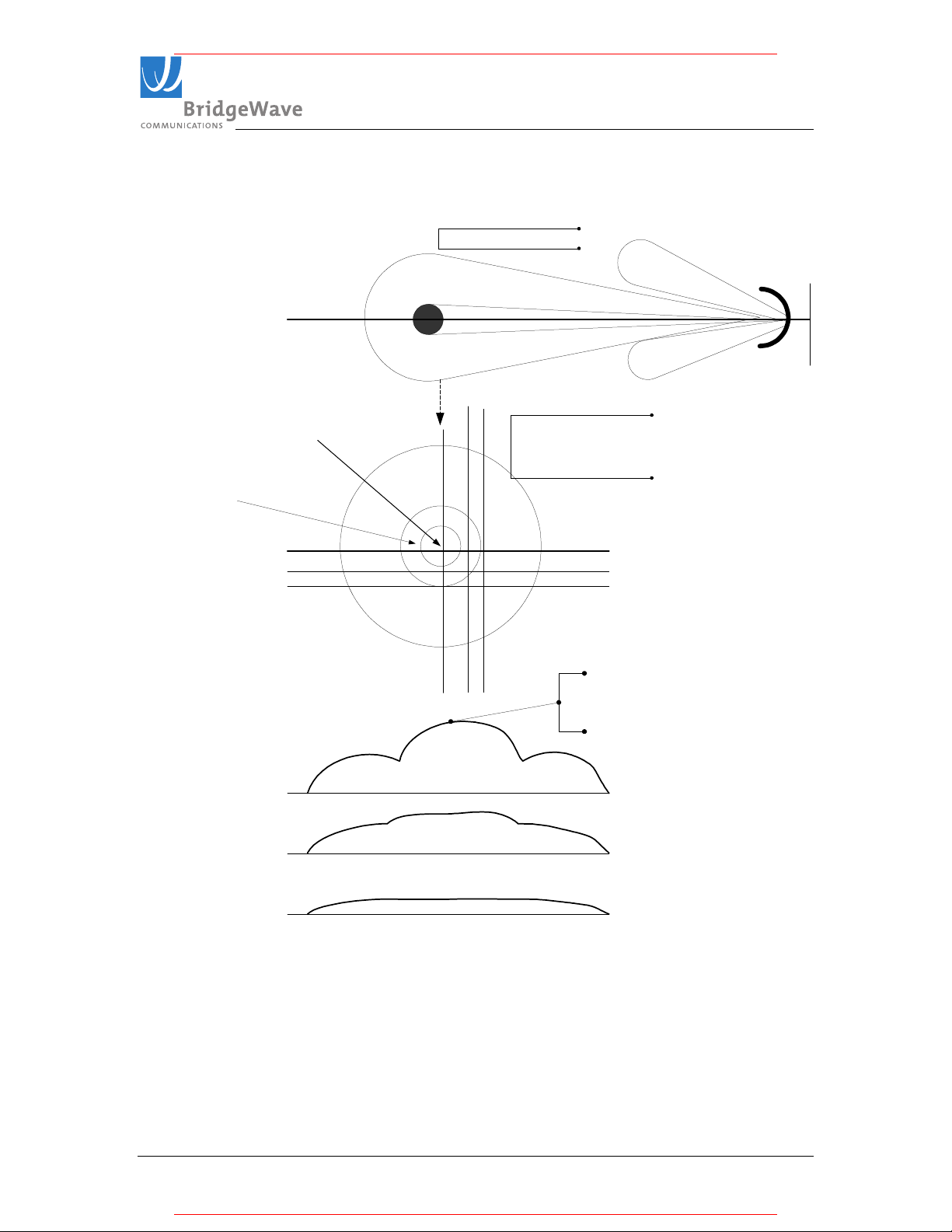
Figure 3-14: The illustration below is an exaggerated cross section of a beam to exemplify a horizontal
RSL level voltage reading against relative locations with an assumed fine tuned vertical position.
Illustration of a main beam
Main Beam
1st Sidelobe on
80GHz is
~degrees away
from main beam
0.9 degrees fro
80GHz
Illustration of a cross section of
the main beam and side lobes
1st Side lobe reading is typically
~20dB down from the main
beam
A
B
C
A represents the desired Magnitude
A B C
A
B
C
of RSL Voltag, notice there are three
clear high points. One should detect
all three points and "back-off" to the
high point.
5) Locking Down Radio Antenna
a) After the target RSL level has been achieved, ensure all bolts are tightened
evenly, securely and ensure the RSL voltage remains unchanged after tightening
is completed.
b) The very narrow beamwidth of this antenna (0.9º) makes it necessary to
completely tighten the bolts of the azimuth adjustment while adjusting the
elevation and vice versa.
580-00519, rev A 28 of 40
Page 29

TM
* For pricing and a quotation, visit MeridianMicrowave.com
* For pricing and a quotation, visit MeridianMicrowave.com
GE/AR80 Installation Manual
c) Always evenly tighten bolts in small fractions at a time to ensure minimum
change to your completed alignment.
6) Connecting the Fiber
a) Connect the fiber cable to one of the radios at a time. The fibers should already be
connected to active network equipment.
b) Verify the fiber LED’s on each of the radios are illuminated solid
Note: The fiber integrity indication on the network equipment could show up or
wn independent of the link status.
do
7) Auto Calibration
a) Once the fiber is connected to the radio, the radio will begin an internal link
calibration.
b) During this time the Link Up LED will blink for approximately 120 seconds.
c) Wait until the Link Up LED is lit solid
d) Verify the Link Quality voltage is 3.0-3.3V (i.e., error free). Repeat steps (a-c) for
the far-end radio. For more details on Auto Calibration see section 3-9 below
8) Removing the Test Cable
Removing the test cable from the radio, replace the rear plastic cover and hand
tighten the back cover nut to the point where the back cover stops (i.e., when it
hits the metal ring on the back metal plate). The installation is now complete.
The most important alignment "tools" for these models are care and patience! It is
recommended that these models be aligned with personnel present at both ends of the
link, and the installers should allow up to 90 minutes to optimally align these units.
The GE/AR80 links have a narrower beamwidth (0.9 degrees) than the GE/AR60 radio
beamwidth (1.4 degrees) and operate at much farther distances.
3.9 Auto Calibration
The Auto Calibration feature scans the RSL level of the system (after the system is
igned) on each radio terminal where the level is calibrated against an internal
al
calibration table that corresponds to an expected receive power level. The radio system is
said to be in Alignment Mode when it is first powered up and no fiber is connected. Once
the alignment is completed; the Auto Calibration mode is triggered ON as soon as the
fiber cable is connected. You will know the radio terminal has initialized the Auto
Calibration when the Link LED is flashing on/off - this lasts for up to 120 seconds. The
radio terminal needs to detect an optical signal of the appropriate Wavelength. For this,
one would require having the fiber optic cables terminated to a fiber port on a switch or
this can be accomplished with a fiber optic jumper cable by connecting the fiber output of
the radio into the fiber input of the radio. Loopback should only be connected long
enough for auto-calibration to start and should be removed immediately.
580-00519, rev A 29 of 40
Page 30

TM
* For pricing and a quotation, visit MeridianMicrowave.com
* For pricing and a quotation, visit MeridianMicrowave.com
GE/AR80 Installation Manual
Losing RF connectivity
When a system loses the RF connection for more than 5 minutes it will trigger the system
to enter an Auto Calibration mode. You can disable this function on the AR80 units via
the NMS. Please review the NMS Manual for further details on disabling this function.
Force Calibration
You can induce a force calibration at anytime by disconnecting DC power and fiber optic
bles from the radio. Powering up the radio terminal while the fiber connectors are
ca
disconnected will induce a Force Calibration, as soon as the fiber optic cables are
reconnected to the radio terminal will.
Also, if using a loop back fiber connector at one end of the link for test purposes, note
that the radio connected to actual network equipment must complete auto calibration
prior to connecting the loop back cable at the other end.
Power Cycling a Radio
When a radio is power cycled and it’s fiber cable is disconnected, it will re-execute the
calibration process. After this, the link will be functioning.
580-00519, rev A 30 of 40
Page 31

TM
* For pricing and a quotation, visit MeridianMicrowave.com
* For pricing and a quotation, visit MeridianMicrowave.com
GE/AR80 Installation Manual
3.10 Test Cable
The alignment procedure is optimized through the use of the provided test cable. This
st cable is designed for use with a digital voltmeter (not provided) to read the Link
te
Quality and Receive Signal Level (RSL) voltage generated by the radio’s receiver.
1. To read the RSL value of the radio, insert GND (ground) and RSL banana plugs
into the voltmeter. Note the RSL voltage. The voltage may be fluctuating; in this
case, note the maximum value seen.
Figure 3-15: Top view of test cable provided to check Link Quality & Receive Signal level
2. To read the Link Quality value of the radio, insert GND (ground) and QUAL
banana plugs into the voltmeter. Note the Link Quality voltage. After the radios
have performed an auto calibration the quality voltage should read 3.0-3.3v if the
link is aligned on the main antenna beam and there are no obstructions (i.e., trees,
buildings, etc…) in the path, the link distance is within the operating parameters of
the radio (see Section 2.4 above), and it is not raining heavily.
580-00519, rev A 31 of 40
Page 32
TM
* For pricing and a quotation, visit MeridianMicrowave.com
* For pricing and a quotation, visit MeridianMicrowave.com
GE/AR80 Installation Manual
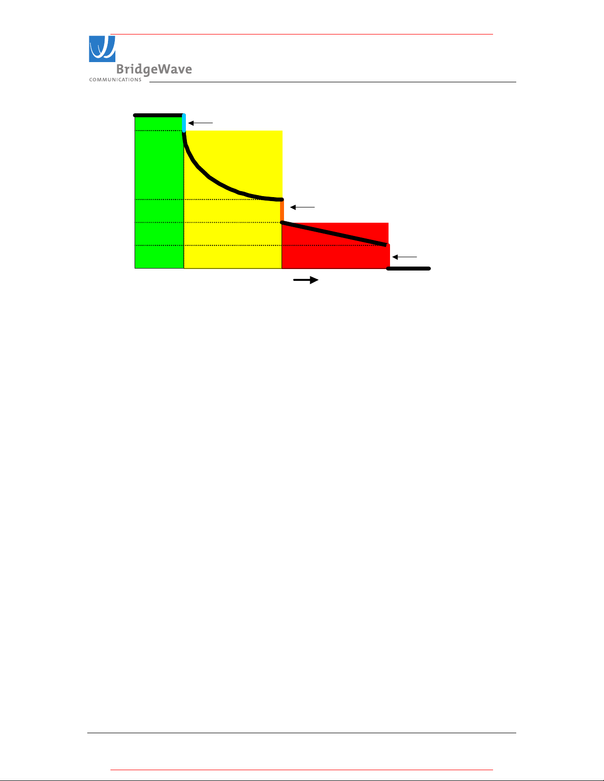
3.3
3.0
NO
ERR ORS
1.5
QUAL Voltage (V)
1.0
0.5
0
Co rrectable Errors Detected
CORRECTED
ERR ORS
(PR E-FEC )
UNCO RRECTED
ERR ORS (POST-FEC )
Erro rs00
Figure 3-16 Quality Voltage Graph
Unco rrec table Errors Detected
Def ramer Unlo cked
• Quality Voltages between 3.0V and 3.3V indicate an error-free wireless link.
• Quality Voltages between 1.5V and 3.0V indicate a low rate of errors that the
forward error correction will correct. The lower the voltage, the more errors are
being corrected.
• Quality Voltages between 0.5V and 1.0V indicate excessive errors in the wireless
link that cannot be corrected by the FEC. To indicate this change in error
performance, the quality voltage will drop from 1.5V to 1.0V in a single step.
• Quality Voltages below 0.5V indicate an unlocked deframer condition. This will
be recognized as a link-down condition.
580-00519, rev A 32 of 40
Page 33

TM
* For pricing and a quotation, visit MeridianMicrowave.com
* For pricing and a quotation, visit MeridianMicrowave.com
GE/AR80 Installation Manual
4 Operation of GE/AR80 & configuration of network equipment
During normal operation, the following conditions should exist at the radio:
1 The power LED should be lit—solid green;
2 The fiber LED should be lit—solid green;
3 The Link Up LED should be lit—solid green; and
4 The Link Quality BER voltage normally should be 3.0-3.3v when it is not
raining.
Figure 4-1: LEDs indicating link is up and operational
The GE80 radio does not require periodic maintenance. However, each end of
the link should be periodically inspected for visible damage or excessive
accumulation of dirt on the antenna’s radome.
580-00519, rev A 33 of 40
Page 34

TM
* For pricing and a quotation, visit MeridianMicrowave.com
* For pricing and a quotation, visit MeridianMicrowave.com
GE/AR80 Installation Manual
4.1 Configuring Network Equipment
The networking equipment that is connected to the GE/AR80 should be checked to
ensure it operates properly over a wired connection. Once this has been confirmed it will
save troubleshooting steps after the radio is installed and connected to the network
equipment.
We strongly recommend the network equipment on both sides of the link be configured
as follows:
• 1000Mbps full-duplex
• Port configured not to enter error-disable state due to link up/down transitions
(since these may occur during periods of very heavy rain)
• For AR model only, ensure to disable the, Installation Auto-Calibration selection
via Set Up GUI section, post installation.
4.2 Check Port Statistics on the Network Equipment
the event the network equipment connected to the GE/AR80 offers the capability
In
below, we recommend you verify the following on the network equipment:
• Link integrity
• There are no receive errors on the link
• Network traffic is flowing in both directions
580-00519, rev A 34 of 40
Page 35
TM
* For pricing and a quotation, visit MeridianMicrowave.com
* For pricing and a quotation, visit MeridianMicrowave.com
GE/AR80 Installation Manual
5 Troubleshooting
The following table provides a summary of possible problems you might encounter while
installing a BridgeWave GE/AR80 link, along with possible causes and their solutions.
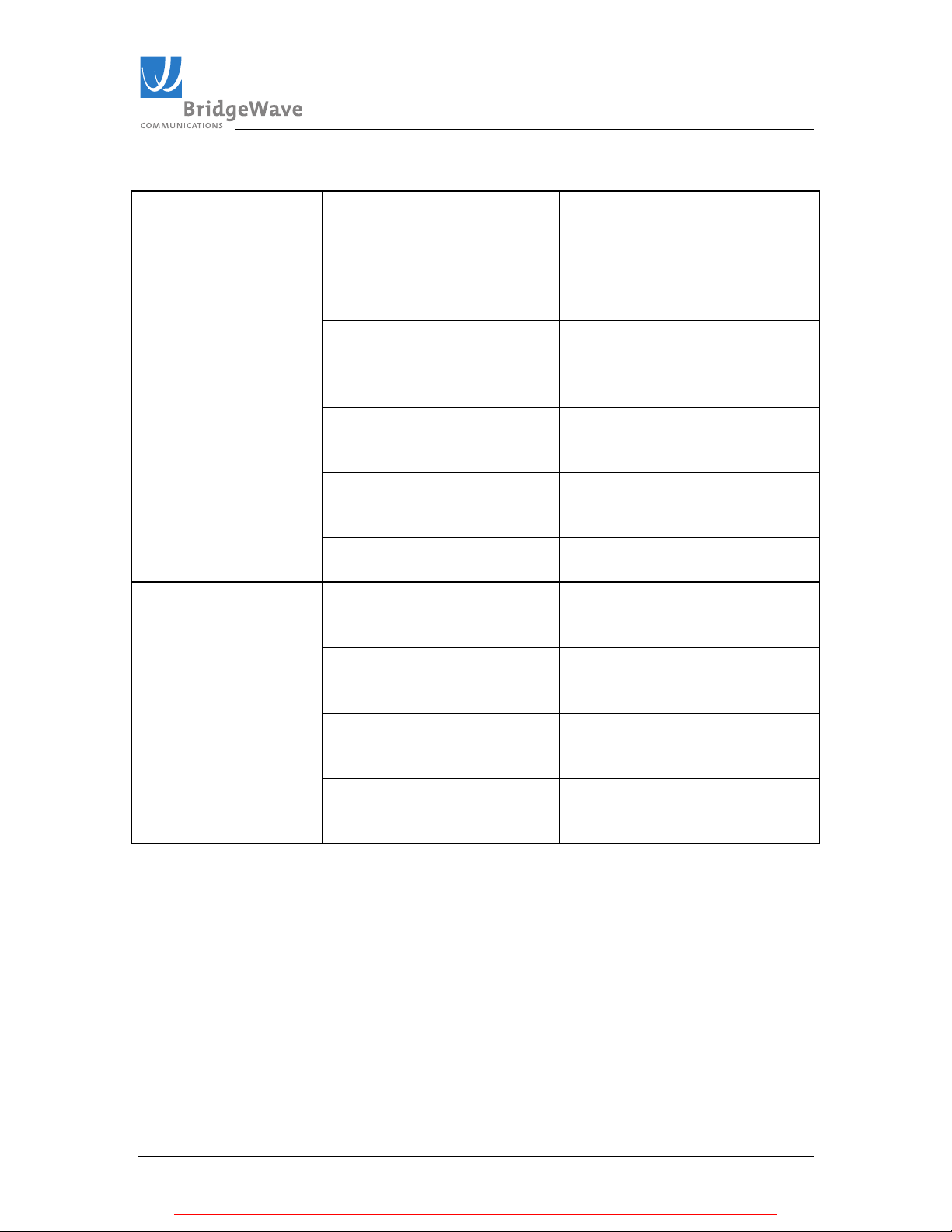
Problem Possible Cause Resolution
No power to radio
Fiber light lit at radio
but not on network
equipment
Radio Link Up LED is
off
Wrong polarity of supply
voltage
The supply voltage measured
at the radio (when
connected) is below 15VDC
Radio link is down and/or
fiber not connected between
remote radio and network
equipment.
TX and RX fiber swapped Try swapping the TX and RX
Error in the configuration of
the Networking equipment
One or both of the fibers
have been damaged
Units are not properly
aligned
Obstacle in link Verify the Line of Sight
Use a DVM to determine the
polarity and voltage on the DC
cable. (See page12)
The cable run is too long or the
cable gauge is too small.
Shorten the length of the cable
or use larger gauge cable. (See
page 12)
This is normal behavior.
Complete end-to-end
installation and re-check.
fibers at one/both ends of the
connection
Verify the configuration of the
network equipment:
Port is turned on and set to
1000Mbps Full Duplex and auto
negotiation is turned off.
Use a loopback connector at the
radio to verify the radio is OK,
repeat at the networking
equipment. Visually inspect the
fiber cable.
The two units are not set to the
same polarization. Verify and if
necessary correct the
polarization setting. (See
section 3.6)
conditions and check for
required clearance (See page 8
for clearance distances).
580-00519, rev A 35 of 40
Page 36
TM
GE/AR80 Installation Manual
* For pricing and a quotation, visit MeridianMicrowave.com
* For pricing and a quotation, visit MeridianMicrowave.com
RSL voltage lower
then expected
Low link quality
voltage
Incorrect calculation of link
distance
Verify that the calculation tool
used and the GPS used both
have the same annotation
system (degree hours minutes
seconds or degree with a
decimal value)
Antennas aligned on side
lobes
Realign antenna to main lobe.
Keep in mind that the first side
lobe is only 1 degree from the
main lobe.
Antennas set to different
polarizations
Verify that both radios are set to
the same polarization. (see
section 3.6)
Installed two high or two low
band radios in one link
Verify that one end of the link is
high and the other end is a low
band radio
Excessive loss through glass Verify RF loss of glass if you
are transmitting from a window.
Obstruction Verify you have a clear line of
site, look for tree and/or other
foliage growth
Antennas are not aligned for
maximum RSL
Verify antenna alignment, use
instructions provided in sections
3.6.-3.8
Auto calibration not
completed
Power cycle units to force auto
calibration cycles. (see chapter
3.9)
Self Interference Check for possible interference
if you have multiple systems on
the same rooftop.
580-00519, rev A 36 of 40
Page 37

TM
GE/AR80 Installation Manual
* For pricing and a quotation, visit MeridianMicrowave.com
* For pricing and a quotation, visit MeridianMicrowave.com
6 RSL Vs Distance Chart
Note: Readings for path distances below one (1) Kilometer should expect RSL level of 3.3Vdc.
580-00519, rev A 37 of 40
Page 38
TM
* For pricing and a quotation, visit MeridianMicrowave.com
* For pricing and a quotation, visit MeridianMicrowave.com
GE/AR80 Installation Manual
7 Standard Limited Warranty and Software License
THE FOLLOWING WARRANTY AND SOFTWARE LICENSE GRANT APPLY ONLY FOR
BRIDGEWAVE COMMUNICATIONS, INC. (“BRIDGEWAVE”) PRODUCTS PURCHASED THROUGH
BRIDGEWAVE AUTHORIZED CHANNEL PARTNERS WITHIN THE UNITED STATES OR CANADA BY
THE ORIGINAL END PURCHASER (“BUYER”). IF BRIDGEWAVE PRODUCTS WERE OBTAINED
THROUGH OTHER CHANNELS, THE FOLLOWING PROVISIONS DO NOT APPLY AND THE SELLING
PARTY SHOULD BE CONTACTED FOR INFORMATION ON ANY PRODUCT WARRANTIES
AVAILABLE.
The following terms apply to the Buyer’s use of BridgeWave hardware products (“Products”) and software products
(“Software”), except to the extent otherwise provided in (a) a separate written agreement between Buyer and
BridgeWave or (b) a “click-on” license agreement as part of the installation and/or downloading process for a particular
Software. To the extent of a conflict between the provisions of these documents, the order of precedence shall be (1)
the written agreement, (2) the click-on license agreement, and (3) this Limited Warranty and Software License.
LIMITED HARDWARE WARRANTY
Limited Hardware Warranty.
shipment to Buyer of the Hardware by BridgeWave or an authorized distributor of BridgeWave products, BridgeWave warrants that
the Products, under normal use and service, shall be free in all material respects from defective design, material and faulty
workmanship and shall operate in all material respects in compliance with the functional specifications, designs, installation
instructions, Product descriptions or technical requirements published by BridgeWave in its Product Manual (“Specifications”). The
foregoing warranty includes Basic Support Services (as defined at www.BridgeWave.com) from BridgeWave during the Warranty
Period. These warranties are provided for the benefit of the original Buyer only. Except for the foregoing warranties, the Products are
supplied “AS IS”.
Remedies for Breach of BridgeWave Warranty. If a Product is in breach of BridgeWave’s warranty during the Warranty Period,
BridgeWave shall, as the sole and exclusive remedy, within thirty (30) calendar days after BridgeWave’s receipt of the returned
Product, repair, replace (with new or refurbished units) or modify, as BridgeWave may solely elect, the Product as necessary so that
the Product complies with the applicable Warranty, or at BridgeWave’s option, refund to the Buyer the Buyer’s purchase price paid
for the Product. Before returning any Products to BridgeWave, Buyer must follow the steps set forth in the Trouble Shooting and
Return Merchandise Procedure explained at www.BridgeWave.com. Any Product returned to BridgeWave must be shipped according
to BridgeWave’s instructions with a properly issued RMA number clearly visible on the outside of the packaging. All Products
returned to BridgeWave shall be shipped DDP (Delivery and Duties Paid) by Buyer to BridgeWave’s designated service facility.
BridgeWave shall prepay return freight charges on repaired or replaced Products when BridgeWave determines, in its sole judgment
that a breach of warranty occurred. BridgeWave may charge its standard rates for any repair or replacement work performed on
returned Product that was not in breach of the warranties herein.
Replacement Product Warranty
the shipment of the replacement Product to Buyer and shall expire on the later of ninety (90) days after shipment date or the last day of
the original Warranty Period with respect to the replaced Product. All replaced parts or Product shall become the property of
BridgeWave.
Limitation on Warranty. Except where they are embedded in the Products, non-BridgeWave manufactured products provided to
Buyer are excluded from any BridgeWave warranty, but may be subject to a warranty provided by the original manufacturer.
BridgeWave shall supply a copy of any such warranty to Buyer on specific written request. BridgeWave warranties are void if: (a)
Buyer integrates or assembles the Product with other products unless integrated or assembled in accordance with applicable
Specifications; (b) the Product is wired, repaired or altered by anyone other than BridgeWave or an authorized representative of
BridgeWave in strict accordance with the applicable Specifications; (c) the Product is improperly handled, stored, installed or
maintained; (d) the Product is used in violation of the applicable Specifications or BridgeWave’s instructions or subjected to misuse,
neglect, accident, abuse or suffers damage due to acts of nature; or (e) the Product is disassembled or its housings are removed by any
person other than a BridgeWave-authorized technician.
EXCLUSION OF CERTAIN WARRANTIES. THE FOREGOING WARRANTIES ARE IN LIEU OF AND EXCLUDE ALL
OTHER EXPRESS AND IMPLIED REPRESENTATION OR WARRANTIES, INCLUDING BUT NOT LIMITED TO, PRODUCT
NON-INFRINGEMENT, OR WARRANTIES OF MERCHANTABILITY, FITNESS FOR A PARTICULAR PURPOSE,
SATISFACTORY QUALITY, ERROR FREE NON-INTERRUPTED OPERATIONS, PROTECTION FROM UNAUTHORIZED
INTRUSION OR ATTACK OR OPERATION AT A SPECIFIED RANGE OR SIGNAL AVAILABILITY OR ARISING FROM A
COURSE OF DEALING, LAW, USAGE OR TRADE PRACTICE. AS EACH PRODUCT IS UNIQUE, BRIDGEWAVE
DISCLAIMS LIABILITY FOR OPERATION OF THE END USER NETWORK AS A WHOLE UNDER ANY WARRANTY
PROVIDED HEREIN. TO THE EXTENT A WARRANTY CANNOT BE EXCLUDED BY LAW, SUCH WARRANTY IS
LIMITED IN DURATION TO THE WARRANTY PERIOD. BECAUSE SOME STATES OR JURISDICTIONS DO NOT ALLOW
LIMITATIONS ON WARRANTY DURATION, THE ABOVE LIMITATION MAY NOT APPLY. THIS WARRANTY GIVES
SPECIFIC LEGAL RIGHTS WHICH MAY BE IN ADDITION TO OTHER RIGHTS WHICH VARY FROM JURISDICTION TO
Subject to limitations below, for a period of twelve (12) months (the “Warranty Period”) after
. The Warranty Period of replacement Product (whether new or refurbished) shall commence upon
580-00519, rev A 38 of 40
Page 39

TM
* For pricing and a quotation, visit MeridianMicrowave.com
* For pricing and a quotation, visit MeridianMicrowave.com
GE/AR80 Installation Manual
JURISDICTION. THIS DISCLAIMER AND EXCLUSION SHALL APPLY EVEN IF THE EXPRESS WARRANTY SET FORTH
ABOVE FAILS OF ITS ESSENTIAL PURPOSE.
SOFTWARE LICENSE
Software License. BridgeWave provides Buyer a non-exclusive, non-transferable limited license (“License”) to use, solely as
embedded in, for execution on or for communication with the Products, the object code (and not the source code) of its Software. For
purposes of this License, Software shall include any BridgeWave provided documentation, component parts, user interfaces,
modifications, upgrades, updates, bug fixes, corrections, backup copies and new releases. Buyer’s use of the Software shall also be
limited by any other restrictions set forth in BridgeWave’s quotation or in BridgeWave’s product catalog, user documentation or web
site.
Title to Software
BridgeWave. Buyer agrees not to take any action inconsistent with such title. Buyer agrees that the Software, including the design and
structure of individual programs, constitutes the trade secrets or copyrighted material of BridgeWave. Buyer agrees not to disclose
such material in any form to any third party and to implement reasonable security measures to protect such material.
License Restrictions. BridgeWave reserves all other rights to the Software not specifically licensed hereunder. Buyer has no right to,
and agrees not to sell, transfer, rent, copy, reverse engineer, reverse compile, decrypt, or reduce to human readable form to gain access
to trade secrets or confidential information, modify or create derivative works of, or grant to any third party any rights in the Software,
or permit any third party to do any of these prohibited acts, without BridgeWave’s prior written consent. Buyer agrees to protect the
Software licensed hereunder in a manner consistent with the maintenance of BridgeWave’s ownership and proprietary rights therein,
including displaying of any copyright and trademark notices in all Software as incorporated by BridgeWave.
Term and Termination. This License is effective until terminated. Buyer may terminate this License at any time, provided that
Buyer’s termination does not entitle Buyer to any refund of purchase or license fees. BridgeWave may terminate Buyer’s rights under
this License immediately upon written notice if Buyer fails to comply with any provision of this License. Upon termination, Buyer
must destroy all copies of Software in its possession or control.
Export. Software and Products, including technical data, may be subject to U.S. export control laws, including the U.S. Export
Administration Act and its associated regulations, and may be subject to export or import regulations in other countries. Buyer agrees
to comply strictly with all such regulations and acknowledges that Buyer has the responsibility to obtain licenses to export, re-export,
or import Software and Products.
Restricted Rights. BridgeWave’s commercial software and commercial computer software documentation is provided to United
States Government agencies in accordance with the terms of this Limited Hardware Warranty and Software License, and per
subparagraph “©” of the “Commercial Computer Software – Restricted Rights” clause at FAR 52.227-19 (June 1987). For DOD
agencies, the restrictions set forth in the “technical Data-Commercial Items” clause at DFARS 252.227-7015 (Nov 1995) shall also
apply.
. Title to the Software, and to any source code for the Software, shall at all times remain solely and exclusively with
LIMITATION OF REMEDY AND LIABILITY PROVISIONS
EXCLUSIVE REMEDIES. THE REMEDIES SET FORTH IN THIS LIMITED WARRANTY AND SOFTWARE LICENSE
ESTABLISH THE ENTIRE OBLIGATION OF BRIDGEWAVE AND BUYER’S SOLE REMEDY IN REGARD TO CLAIMS
RELATING TO BREACH OF WARRANTY OR INTELLECTUAL PROPERTY RIGHTS INCLUDING BUT NOT LIMITED TO
CLAIMS DIRECTED TO THE INFRINGEMENT OR MISAPPROPRIATION OF PATENTS, COPYRIGHTS, TRADE SECRETS
AND OTHER PROPRIETARY RIGHTS FOR THE PRODUCTS.
NO CONSEQUENTIAL DAMAGES. IN NO EVENT SHALL EITHER PARTY, OR EITHER PARTY’S SUPPLIERS,
OFFICERS, DIRECTORS, EMPLOYEES, AGENTS, SHAREHOLDERS OR CONTRACTORS (“RELATED PARTIES”), BE
LIABLE TO THE OTHER PARTY OR ITS RELATED PARTIES FOR CONSEQUENTIAL, INDIRECT, INCIDENTAL,
SPECIAL, PUNITIVE OR EXEMPLARY DAMAGES OR FOR COST OF COVER, LOST REVENUES, LOST PROFITS OR
LOST DATA OR OTHER ECONOMIC LOSS ARISING FROM ANY CAUSE INCLUDING BUT NOT LIMITED TO BREACH
OF WARRANTY, BREACH OF CONTRACT, TORT, STRICT LIABILITY, OR FAILURE OF ESSENTIAL PURPOSE EVEN IF
BRIDGEWAVE HAS BEEN ADVISED OF THE POSSIBILITY OF SUCH DAMAGES. THE FOREGOING LIMITATIONS
SHALL APPLY EVEN IF THE ABOVE-STATED WARRANTY FAILS OF ITS ESSENTIAL PURPOSE. BECAUSE SOME
STATES OR JURISDICTIONS DO NOT ALLOW LIMITATIONS OR EXCLUSIONS OF CONSEQUENTIAL OR INCIDENTAL
DAMAGES, THE ABOVE LIMITATION MAY NOT APPLY TO BUYER.
LIMIT ON LIABILITY. THE MAXIMUM LIABILITY OF BRIDGEWAVE, AND ITS RELATED PARTIES, TAKEN AS A
WHOLE, FOR ANY AND ALL CLAIMS IN CONNECTION WITH THE PRODUCTS AND SOFTWARE, INCLUDING BUT
NOT LIMITED TO CLAIMS FOR BREACH OF WARRANTY, BREACH OF CONTRACT, TORT, STRICT LIABILITY,
FAILURE OF ESSENTIAL PURPOSE OR OTHERWISE, SHALL IN NO CIRCUMSTANCE EXCEED THE PURCHASE PRICE
PAID BY BUYER TO BRIDGEWAVE OR BRIDGEWAVE’S AUTHORIZED CHANNEL PARTNERS FOR THE PRODUCTS
AND SOFTWARE.
Statute of Limitations
shall be commenced within one (1) year after the cause of action accrues, or reasonably could have been discovered, or it shall be
deemed waived and barred.
580-00519, rev A 39 of 40
. Any action for breach of or to enforce any right under this Limited Hardware Warranty or Software License
Page 40

TM
* For pricing and a quotation, visit MeridianMicrowave.com
* For pricing and a quotation, visit MeridianMicrowave.com
GE/AR80 Installation Manual
Administrative Provisions. This Limited Hardware Warranty and Software License shall be governed by and construed in
accordance with the laws of the State of California, without reference to principles of conflict of laws, provided that for customers
located in a member state of the European Union, Norway or Switzerland, English law shall apply. The United Nations Convention on
the International Sale of Goods shall not apply. If any portion hereof is found to be void or unenforceable, the remaining provisions of
the Limited Hardware Warranty and Software License shall remain in full force and effect. Except as expressly provided herein, the
Limited Hardware Warranty and Software License constitutes the entire agreement between the parties with respect to warranties on
the Hardware and Licensing of the Software, and supersedes any conflicting or additional terms contained in any prior or
contemporaneous discussion, negotiation or agreement, including those in any purchase order or order acknowledgment.
580-00519, rev A 40 of 40
 Loading...