

Page 1
6
FLEX4G-LITE
User Interface Manual
040-57105-01
Page 2

Page 2 of 84
040-57105-01
Description
Revision
Date
FLEX4G-LITE User Interface Manual created
1
10/26/2016
Copyright Notice and Disclaimer
©2016 BridgeWave Communications. All Rights Reserved.
No portion of this publication may be reproduced, copied or distributed without the
written consent of BridgeWave. BridgeWave reserves the right to update or change
the material of this publication at any time without notice. BridgeWave has made
every effort to ensure that the information and the instructions contained in the
publication are correct and is not responsible for any errors or omissions due to
typing, printing or editing of this document.
Purchasers of BridgeWave products should make their own evaluation to determine
the suitability of each product for their specific application. BridgeWave obligations
regarding the use or application of its products shall be limited to those commitments
to the purchaser set forth in its Standard Terms and Conditions of Sale for a delivered
product.
This publication has been prepared for professional and properly trained personnel,
and the customer assumes full responsibility when using the information herein.
The software provided and described in this guide is furnished under and is subject to
a license and nondisclosure agreement.
Export Control
All BridgeWave radio products are restricted commodities that fall under ECCN 5A002
of the Department of Commerce. These products are "ENC restricted" under section
740.17(b)(2) of the Export Administration Regulations (EAR). BridgeWave products
may only be exported, re-exported, transferred, or retransferred in accordance with
Export Administration Regulations. Diversion contrary to U.S. law is expressly
prohibited
Product Compatibility
While every effort has been made to verify operation of this product with many
different communications products and networks, BridgeWave makes no claim of
compatibility between its products and other vendors’ equipment. It is assumed that
users have thoroughly evaluated this product’s performance in the communications
environment in which it will be used
www.bridgewave.com
Revision History
Page 3

Page 3 of 84
040-57105-01
Contents
1 General Information ................................................................................ 6
Introduction .............................................................................. 6
Product Compatibility .................................................................. 7
Safety and Regulatory ................................................................ 7
RF Compatibility and Regulatory Information .................................. 9
Std. Limited Warranty & SW License ........................................... 10
2 Product Description and Overview ......................................................... 13
FLEX4G-LITE Description ........................................................... 13
3 Local Management Access ..................................................................... 15
Tools and equipment needed to access and manage the radio. ....... 15
Connection to FLEX4G-LITE ....................................................... 15
Radio Setup ............................................................................. 18
Setting the Radio’s IP Address ................................................... 19
Detailed Status Page................................................................. 23
Link Statistics Page .................................................................. 26
Configuration Page ................................................................... 27
Modem Firmware Upload Page ................................................... 31
Installation Page ...................................................................... 33
Diagnostics Page ................................................................... 35
Security Page ........................................................................ 36
Factory Page ......................................................................... 38
Logs Page ............................................................................. 39
4 FLEX4G-LITE – Switch Functions ........................................................... 41
Switch Menu Options ................................................................ 41
5 UI & MODEM Update Procedures via CLI ................................................ 76
Tools and Methods ................................................................... 76
Update Using Command Line Interface ........................................ 76
Update FPGA/Modem Firmware .................................................. 78
Updating UI using the GUI interface ............................................ 80
Updating FPGA/Modem Firmware using the GUI interface ............... 82
Page 4

Page 4 of 84
040-57105-01
Table of Figures
Figure 1: FLEX4G-LITE Point to Point System .......................................... 6
Figure 2: FLEX4G-LITE Power and Data Connection ................................ 15
Figure 3: Main Login .......................................................................... 16
Figure 4: Main Window ....................................................................... 16
Figure 5: Radio Setup Page................................................................. 18
Figure 6: IP Configuration Page ............................................................ 20
Figure 7: Sample Host IP Configuration ................................................ 23
Figure 8: Detailed Status Page ............................................................ 24
Figure 9: Link Statistics Page .............................................................. 26
Figure 10: Configuration Page ............................................................. 27
Figure 11: System Information Configuration ........................................ 28
Figure 12: SNMP System Configuration ................................................ 29
Figure 13: Trap Configuration Page ...................................................... 30
Figure 14: Trap Configuration Example ................................................. 31
Figure 15: Modem Firmware Upload Example ........................................ 32
Figure 17: Installation Pages ............................................................... 33
Figure 18: Diagnostic Page / Fault Recovery .......................................... 35
Figure 19: Security Licensing Page ...................................................... 36
Figure 21: Log Hyperlink Page............................................................. 39
Figure 22: Log Page........................................................................... 39
Figure 23: Total System Log Entries ..................................................... 40
Figure 24: System Log Information Buttons .......................................... 41
Figure 25: Switch Submenu Options .................................................... 41
Figure 26: IP, Multiple Management Interfaces ...................................... 43
Figure 27: Save IP Configuration ......................................................... 43
Figure 28: VLAN Configuration ............................................................ 43
Figure 29: VLAN Port Access ............................................................... 44
Figure 30: NTP Configuration Page ....................................................... 45
Figure 31: Time Zone Configuration Page ............................................. 46
Figure 32: System Log Configuration Page ............................................ 47
Figure 34: User and Access Level ........................................................ 50
Figure 35: Add User/Password Setting .................................................. 51
Figure 36: Privilege Level Configuration Page ........................................ 52
Figure 37: Authentication Method Configuration Page ............................. 53
Figure 38: SSH Configuration Settings .................................................. 54
Figure 40: Authentication Method Configuration Page ............................. 55
Figure 41: Access Management Configuration Page ................................ 56
Figure 42: Add New Entry to Access Management Configuration............... 57
Figure 43: SNMP System Configuration ................................................ 57
Figure 44: Trap Configuration Settings ................................................. 58
Figure 45: Example of Setting Trap Destination ..................................... 59
Figure 46: SNMPv3 Community Configuration Page ................................ 59
Figure 47: SNMPv2 Community Configuration, New Entry ....................... 60
Page 5

Page 5 of 84
040-57105-01
Figure 48: Static Aggregation Configuration .......................................... 61
Figure 49: LACP Port Configuration ...................................................... 63
Figure 50: Example of LACP Configuration ............................................ 64
Figure 51: Port State Overview ........................................................... 65
Figure 53: Example of Detailed Port Statistics ....................................... 66
Figure 54: Utility Buttons ................................................................... 66
Figure 55: Example Port Statistics Overview ......................................... 67
Figure 56: Restart Device (ODU) ......................................................... 69
Figure 57: Factory Defaults ................................................................. 69
Figure 58: Software Upload ................................................................ 70
Figure 59: GUI Software Images ......................................................... 71
Figure 60: Save Running Configuration ................................................. 72
Figure 61: Download Configuration Page .............................................. 72
Figure 62: Upload Configuration .......................................................... 73
Figure 63: Activate Configuration(s) ..................................................... 74
Figure 64: Delete Configuration File ..................................................... 74
Figure 65: CLI Periodic Status Message ................................................ 77
Figure 66: Software Upload ................................................................ 80
Figure 69: Controller Version .............................................................. 81
Figure 70: Software Image Selection ................................................... 81
Figure 71: Modem Firmware Upload ..................................................... 82
Figure 72: Modem Firmware Version Location ........................................ 82
Figure 73: TFTP Server IP Address ....................................................... 83
Figure 74: Modem Firmware Version Selection ....................................... 83
Figure 75: Modem Firmware Version .................................................... 83
Page 6
Page 6 of 84
040-57105-01
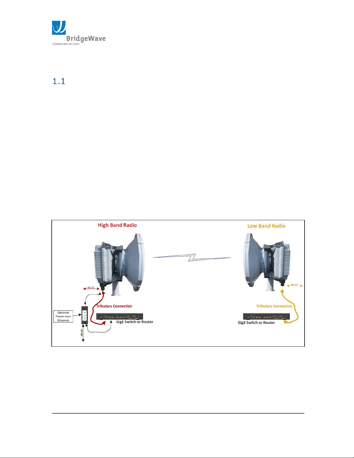
Figure 1: FLEX4G-LITE Point to Point System
1 General Information
Introduction
This manual provides an overview and general introduction to the user
interface options of the FLEX4G-LITE millimeter wave radio. It contains the
information necessary to set up, operate, and maintain a link.
Bridgewave’s FLEX4G-LITE product family provides network designers with a
point-to-point broadband radio that delivers broadband wireless Ethernet IPbased services.
Requiring no server room installation, the all-outdoor ready FLEX4G-LITE
installs quickly and delivers the lowest cost per gigabit wireless solution in the
industry. FLEX4G-LITE is the ideal choice wherever rapid deployment of
Carrier-grade Ethernet service is required.
The FLEX4G-LITE system consists of a radio unit and antenna.
Figure 1 illustrates a typical FLEX4G-LITE radio link.
Page 7
Page 7 of 84
040-57105-01
CAUTION
CAUTION
Product Compatibility
While every effort has been made to verify operation of this product with an
array of different communications products and networks, BridgeWave makes
no claim of compatibility between its products and other vendors’ equipment.
Carefully evaluate this product’s applicability and projected performance
characteristics in the communications environment in which it will be used.
Safety and Regulatory
United States of America
The following general safety precautions must be observed during all phases
of operation and service of the products covered in this manual. Failure to
comply with these precautions or with specific warnings elsewhere in this
manual can void the warranty.
Do not stand directly in front of an energized antenna.
Do not install or operate the equipment in the presence of or close to
flammable fumes or gases. Operating any electrical instrument in such
an environment is a safety hazard.
BridgeWave radios meet all applicable U.S.A. FCC safety requirements
for general population exposure to radio frequency emissions; however,
it is best to avoid prolonged, unnecessary exposure to the waveguide
opening while it is operating.
Please refer to Articles 810 and 830 of the National Electrical Code,
ANSI/NFPA No. 70, for installations in the U.S.A. for information
regarding proper grounding and applicable lightning protection for DC
cables.
Outdoor equipment must be properly grounded to provide protection
against voltage surges and built-up static charges. In the event of a
short circuit, grounding reduces (but does not eliminate) the risk of
electrical shock.
Changes or modifications not expressly approved (in writing) by
BridgeWave’s Engineering and/or Product Management personnel can
void the warranty. For installations in all other countries, implement
protection in accordance with the safety standards and regulatory
requirements of the country where the equipment is to be installed.
Protection from Lightning
Article 810 of the US National Electric Department of Energy Handbook 1996 specifies
that radio and television lead-in cables must have adequate surge protection at or
near the point of entry to the building. The code specifies that any shielded cable
Page 8
Page 8 of 84
040-57105-01
CAUTION
CAUTION
CAUTION
CAUTION
from an external antenna must have the shield directly connected to a 10 AWG wire
that connects to the building ground electrode.
Protection from RF Emissions
It is hazardous to look into or stand in front of an active antenna aperture. Do not
stand in front of or look into an antenna without first ensuring the associated
transmitter or transmitters are switched off. Do not look into the waveguide port of an
ODU when the radio is active.
LASER SAFETY NOTICE
This product complies with CFR 1040.10, 1040.11 and EN (IEC) 60825-1 regulations
and safety standards. The product may include a Class 1 laser utilized as a fiber optic
driver. Class 1 lasers do not emit radiation at known hazardous levels.
However, it is recommended that maintenance or service personnel should never look
at an open fiber end or connector that is carrying a live signal. During use, this optical
fiber communications system is completely enclosed except if an accidental break
occurs in the system cable, or if the patch cable becomes accidentally disconnected
from the demarcation box.
There are no controls or adjustments other than power ON/OFF that may be accessed
by the user.
Risk of Personal Injury from Fiber Optics
DANGER: Invisible laser radiation. Avoid direct eye exposure to the end
of a fiber, fiber cord, or fiber pigtail. The infrared light used in fiber
optics systems is invisible, but can cause serious injury to the eye.
WARNING: Never touch exposed fiber with any part of your body. Fiber
fragments can enter the skin and are difficult to detect and remove.
CAUTION: Use of controls or adjustments or performance of procedure other than
those specified in this Manual may result in hazardous radiation exposure.
CONSTRUCTION SAFETY NOTICE
Note that each locality has its own codes of safety and construction. Equipment
installations must comply with these codes. It is the installer/user’s responsibility to
understand what codes apply and to ensure that the installation conforms to these
codes.
Input Power Requirements
Do not turn on the power before reading BridgeWave’s product documentation. This
device has a -48 VDC direct current input at less than 50VA.
NOTE: The power requirement for the FLEX4G-LITE is 48VDC at 32W.
Page 9

Page 9 of 84
040-57105-01
RF Compatibility and Regulatory Information
This device, in accordance with FCC Part 15B and Part2, complies with Part 15
Subpart J, and Part 101 Subpart Q, of the U.S.A. Federal Communication Commission
rules.
In the U.S.A., millimeter wave radio transmission equipment operating in the 71-76
and 81-86 GHz frequency ranges must be registered with the FCC as provided for in
Part 101 of the FCC regulations.
Proper operating licenses must be obtained to operate radios in the 71-86 GHz
frequency band in the U.S.A. and most other countries.
Check with your country’s wireless regulatory body for licensing in your area. Do not
install the FLEX4G-LITE without an approved license.
For additional information on licensing or regulatory information, please contact
BridgeWave at [email protected] .
European Union
This product has been designed to comply with CE markings in accordance
with the requirements of European Directive 1995/5/EC.
This product has been designed to comply with the requirements of European
Directives.
This equipment must be permanently earthed for protection and functional
purposes. To make a protective earth connection, use the grounding point
located on the System ODU using a minimum amount of 16AWG grounding
cable or according to local electrical code.
This apparatus is intended to be accessible only to authorized personnel.
Failure to prevent access by unauthorized personnel will invalidate any
approval given to this apparatus.
This product is in full compliance with the following standards:
RF EN 302 217-3 1.3.1
EMC EN 301 489-4
Safety IEC 60950-1, -22
Operation EN 300 019-1-4 Class 4.1E
Storage EN 300 019-1-1 Class 1.2
Transportation EN 300 019-1-2 Class 2.2
Page 10

Page 10 of 84
040-57105-01
IP67
Std. Limited Warranty & SW License
THE FOLLOWING WARRANTY AND SOFTWARE LICENSE GRANT APPLY ONLY FOR BRIDGEWAVE
COMMUNICATIONS (“BRIDGEWAVE”) PRODUCTS PURCHASED THROUGH BRIDGEWAVE
AUTHORIZED CHANNEL PARTNERS WITHIN THE UNITED STATES OR CANADA BY THE ORIGINAL
END PURCHASER (“BUYER”). IF BRIDGEWAVE PRODUCTS WERE OBTAINED THROUGH OTHER
CHANNELS, THE FOLLOWING PROVISIONS DO NOT APPLY AND THE SELLING PARTY SHOULD BE
CONTACTED FOR INFORMATION ON ANY PRODUCT WARRANTIES AVAILABLE.
The following terms apply to the Buyer’s use of BridgeWave hardware products (“Products”) and software
products (“Software”), except to the extent otherwise provided in (a) a separate written agreement
between Buyer and BridgeWave or (b) a “click-on” license agreement as part of the installation and/or
downloading process for a particular Software. To the extent of a conflict between the provisions of these
documents, the order of precedence shall be (1) the written agreement, (2) the click-on license agreement,
and (3) this Limited Warranty and Software License.
LIMITED HARDWARE WARRANTY
Limited Hardware Warranty. Subject to limitations below, for a period of twelve (12) months (the
“Warranty Period”) after shipment to Buyer of the Hardware by BridgeWave or an authorized distributor of
BridgeWave products, BridgeWave warrants that the Products, under normal use and service, shall be free
in all material respects from defective design, material and faulty workmanship and shall operate in all
material respects in compliance with the functional specifications, designs, installation instructions, Product
descriptions or technical requirements published by BridgeWave in its Product Manual (“Specifications”).
The foregoing warranty includes Basic Support Services (as defined at www.BridgeWave.com) from
BridgeWave during the Warranty Period. These warranties are provided for the benefit of the original Buyer
only. Except for the foregoing warranties, the Products are supplied “AS IS”.
Remedies for Breach of BridgeWave Warranty. If a Product is in breach of BridgeWave’s warranty
during the Warranty Period, BridgeWave shall, as the sole and exclusive remedy, within thirty (30) calendar
days after BridgeWave’s receipt of the returned Product, repair, replace (with new or refurbished units) or
modify, as BridgeWave may solely elect, the Product as necessary so that the Product complies with the
applicable Warranty, or at BridgeWave’s option, refund to the Buyer the Buyer’s purchase price paid for the
Product. Before returning any Products to BridgeWave, Buyer must follow the steps set forth in the Trouble
Shooting and Return Merchandise Procedure explained at www.BridgeWave.com. Any Product returned to
BridgeWave must be shipped according to BridgeWave’s instructions with a properly issued RMA number
clearly visible on the outside of the packaging. All Products returned to BridgeWave shall be shipped DDP
(Delivery and Duties Paid) by Buyer to BridgeWave’s designated service facility. BridgeWave shall prepay
return freight charges on repaired or replaced Products when BridgeWave determines, in its sole judgment
that a breach of warranty occurred. BridgeWave may charge its standard rates for any repair or
replacement work performed on returned Product that was not in breach of the warranties herein.
Replacement Product Warranty. The Warranty Period of replacement Product (whether new or
refurbished) shall commence upon the shipment of the replacement Product to Buyer and shall expire on
the later of ninety (90) days after shipment date or the last day of the original Warranty Period with
respect to the replaced Product. All replaced parts or Product shall become the property of BridgeWave.
Limitation on Warranty. BridgeWave warranties are void if: (a) Buyer integrates or assembles the
Product with other products unless integrated or assembled in accordance with applicable Specifications;
(b) the Product is wired, repaired or altered by anyone other than BridgeWave or an authorized
representative of BridgeWave in strict accordance with the applicable Specifications; (c) the Product is
improperly handled, stored, installed or maintained; (d) the Product is used in violation of the applicable
Specifications or BridgeWave’s instructions or subjected to misuse, neglect, accident, abuse or suffers
damage due to acts of nature; or (e) the Product is disassembled or its housings are removed by any
person other than a BridgeWave-authorized technician.
EXCLUSION OF CERTAIN WARRANTIES. THE FOREGOING WARRANTIES ARE IN LIEU OF AND EXCLUDE
ALL OTHER EXPRESS AND IMPLIED REPRESENTATION OR WARRANTIES, INCLUDING BUT NOT LIMITED TO,
PRODUCT NON-INFRINGEMENT, OR WARRANTIES OF MERCHANTABILITY, FITNESS FOR A PARTICULAR
PURPOSE, SATISFACTORY QUALITY, ERROR FREE NON-INTERRUPTED OPERATIONS, PROTECTION FROM
Page 11

Page 11 of 84
040-57105-01
UNAUTHORIZED INTRUSION OR ATTACK OR OPERATION AT A SPECIFIED RANGE OR SIGNAL
AVAILABILITY OR ARISING FROM A COURSE OF DEALING, LAW, USAGE OR TRADE PRACTICE. AS EACH
PRODUCT IS UNIQUE, BRIDGEWAVE DISCLAIMS LIABILITY FOR OPERATION OF THE END USER NETWORK
AS A WHOLE UNDER ANY WARRANTY PROVIDED HEREIN. TO THE EXTENT A WARRANTY CANNOT BE
EXCLUDED BY LAW, SUCH WARRANTY IS LIMITED IN DURATION TO THE WARRANTY PERIOD. BECAUSE
SOME STATES OR JURISDICTIONS DO NOT ALLOW LIMITATIONS ON WARRANTY DURATION, THE ABOVE
LIMITATION MAY NOT APPLY. THIS WARRANTY GIVES SPECIFIC LEGAL RIGHTS WHICH MAY BE IN
ADDITION TO OTHER RIGHTS WHICH VARY FROM JURISDICTION TO JURISDICTION. THIS DISCLAIMER
AND EXCLUSION SHALL APPLY EVEN IF THE EXPRESS WARRANTY SET FORTH ABOVE FAILS OF ITS
ESSENTIAL PURPOSE.
SOFTWARE LICENSE
Software License. BridgeWave provides Buyer a non-exclusive, non-transferable limited license
(“License”) to use, solely as embedded in, for execution on or for communication with the Products, the
object code (and not the source code) of its Software. For purposes of this License, Software shall include
any BridgeWave provided documentation, component parts, user interfaces, modifications, upgrades,
updates, bug fixes, corrections, backup copies and new releases. Buyer’s use of the Software shall also be
limited by any other restrictions set forth in BridgeWave’s quotation or in BridgeWave’s product catalog,
user documentation or web site.
Title to Software. Title to the Software, and to any source code for the Software, shall at all times remain
solely and exclusively with BridgeWave. Buyer agrees not to take any action inconsistent with such title.
Buyer agrees that the Software, including the design and structure of individual programs, constitutes the
trade secrets or copyrighted material of BridgeWave. Buyer agrees not to disclose such material in any
form to any third party and to implement reasonable security measures to protect such material.
License Restrictions. BridgeWave reserves all other rights to the Software not specifically licensed
hereunder. Buyer has no right to, and agrees not to sell, transfer, rent, copy, reverse engineer, reverse
compile, decrypt, or reduce to human readable form to gain access to trade secrets or confidential
information, modify or create derivative works of, or grant to any third party any rights in the Software, or
permit any third party to do any of these prohibited acts, without BridgeWave’s prior written consent.
Buyer agrees to protect the Software licensed hereunder in a manner consistent with the maintenance of
BridgeWave’s ownership and proprietary rights therein, including displaying of any copyright and trademark
notices in all Software as incorporated by BridgeWave.
Term and Termination. This License is effective until terminated. Buyer may terminate this License at
any time, provided that Buyer’s termination does not entitle Buyer to any refund of purchase or license
fees. BridgeWave may terminate Buyer’s rights under this License immediately upon written notice if Buyer
fails to comply with any provision of this License. Upon termination, Buyer must destroy all copies of
Software in its possession or control.
Export. Software and Products, including technical data, may be subject to U.S. export control laws,
including the U.S. Export Administration Act and its associated regulations, and may be subject to export or
import regulations in other countries. Buyer agrees to comply strictly with all such regulations and
acknowledges that Buyer has the responsibility to obtain licenses to export, re-export, or import Software
and Products.
Restricted Rights. BridgeWave’s commercial software and commercial computer software documentation
is provided to United States Government agencies in accordance with the terms of this Limited Hardware
Warranty and Software License, and per subparagraph “©” of the “Commercial Computer Software –
Restricted Rights” clause at FAR 52.227-19 (June 1987). For DOD agencies, the restrictions set forth in the
“technical Data-Commercial Items” clause at DFARS 252.227-7015 (Nov 1995) shall also apply.
LIMITATION OF REMEDY AND LIABILITY PROVISIONS
EXCLUSIVE REMEDIES. THE REMEDIES SET FORTH IN THIS LIMITED WARRANTY AND SOFTWARE
LICENSE ESTABLISH THE ENTIRE OBLIGATION OF BRIDGEWAVE AND BUYER’S SOLE REMEDY IN REGARD
TO CLAIMS RELATING TO BREACH OF WARRANTY OR INTELLECTUAL PROPERTY RIGHTS INCLUDING BUT
NOT LIMITED TO CLAIMS DIRECTED TO THE INFRINGEMENT OR MISAPPROPRIATION OF PATENTS,
COPYRIGHTS, TRADE SECRETS AND OTHER PROPRIETARY RIGHTS FOR THE PRODUCTS.
NO CONSEQUENTIAL DAMAGES. IN NO EVENT SHALL EITHER PARTY, OR EITHER PARTY’S SUPPLIERS,
OFFICERS, DIRECTORS, EMPLOYEES, AGENTS, SHAREHOLDERS OR CONTRACTORS (“RELATED PARTIES”),
Page 12

Page 12 of 84
040-57105-01
BE LIABLE TO THE OTHER PARTY OR ITS RELATED PARTIES FOR CONSEQUENTIAL, INDIRECT,
INCIDENTAL, SPECIAL, PUNITIVE OR EXEMPLARY DAMAGES OR FOR COST OF COVER, LOST REVENUES,
LOST PROFITS OR LOST DATA OR OTHER ECONOMIC LOSS ARISING FROM ANY CAUSE INCLUDING BUT
NOT LIMITED TO BREACH OF WARRANTY, BREACH OF CONTRACT, TORT, STRICT LIABILITY, OR FAILURE
OF ESSENTIAL PURPOSE EVEN IF BRIDGEWAVE HAS BEEN ADVISED OF THE POSSIBILITY OF SUCH
DAMAGES. THE FOREGOING LIMITATIONS SHALL APPLY EVEN IF THE ABOVE-STATED WARRANTY FAILS
OF ITS ESSENTIAL PURPOSE. BECAUSE SOME STATES OR JURISDICTIONS DO NOT ALLOW LIMITATIONS
OR EXCLUSIONS OF CONSEQUENTIAL OR INCIDENTAL DAMAGES, THE ABOVE LIMITATION MAY NOT
APPLY TO BUYER.
LIMIT ON LIABILITY. THE MAXIMUM LIABILITY OF BRIDGEWAVE, AND ITS RELATED PARTIES, TAKEN AS
A WHOLE, FOR ANY AND ALL CLAIMS IN CONNECTION WITH THE PRODUCTS AND SOFTWARE, INCLUDING
BUT NOT LIMITED TO CLAIMS FOR BREACH OF WARRANTY, BREACH OF CONTRACT, TORT, STRICT
LIABILITY, FAILURE OF ESSENTIAL PURPOSE OR OTHERWISE, SHALL IN NO CIRCUMSTANCE EXCEED THE
PURCHASE PRICE PAID BY BUYER TO BRIDGEWAVE OR BRIDGEWAVE’S AUTHORIZED CHANNEL PARTNERS
FOR THE PRODUCTS AND SOFTWARE.
Statute of Limitations. Any action for breach of or to enforce any right under this Limited Hardware
Warranty or Software License shall be commenced within one (1) year after the cause of action accrues, or
reasonably could have been discovered, or it shall be deemed waived and barred.
Administrative Provisions. This Limited Hardware Warranty and Software License shall be governed by
and construed in accordance with the laws of the State of California, without reference to principles of
conflict of laws, provided that for customers located in a member state of the European Union, Norway or
Switzerland, English law shall apply. The United Nations Convention on the International Sale of Goods
shall not apply. If any portion hereof is found to be void or unenforceable, the remaining provisions of the
Limited Hardware Warranty and Software License shall remain in full force and effect. Except as expressly
provided herein, the Limited Hardware Warranty and Software License constitutes the entire agreement
between the parties with respect to warranties on the Hardware and Licensing of the Software, and
supersedes any conflicting or additional terms contained in any prior or contemporaneous discussion,
negotiation or agreement, including those in any purchase order or order acknowledgment.
Page 13

Page 13 of 84
040-57105-01
2 Product Description and Overview
The FLEX4G-LITE product is designed to provide the network operator the flexibility of
providing first mile access, as well as backhaul, for gigabit Ethernet networks.
“Plug & Play” simple installation and alignment
Outdoor only capability/no Indoor unit
10/100/1000BaseT Gigabit Ethernet Interface
2xSFP Inputs
Optional CPRI Interface with line rate options of 1, 2, 3 & 4
Local Management Interface using CLI or HTML based web browser
Remote management using SNMP v1,2 &3
48 VDC Input (via either POE or direct using a two wire connection)
Integrated & Direct slip-fit Antenna Mount options
Low latency
Frequency agile
FLEX4G-LITE Description
The FLEX4G-LITE millimeter wave radio is a point-to-point fixed wireless, ultra-high
capacity broadband access product operating in the upper millimeter wave spectrum
from 71-76 GHz and 81-86 GHz. The FLEX4G-LITE is capable of native Ethernet
payloads from 83 – 3000Mbps, full duplex. The radio system is designed for rapid
deployment.
In most locations, the FLEX4G-LITE will have a better than 99.995% link availability
at approximately 1 mile or 1.6Km. Actual path performance is dependent upon local
climate conditions. Please contact BridgeWave or your authorized representative for
additional information.
The FLEX4G-LITE is available in two model configurations. The FLEX4G-LITE-INT
model incorporates an integrated 38 dBi antenna (ETSI only). The Direct Mount
model (ANSI and ETSI) uses the custom slip-mount antenna interface for use with
1ft/30cm, 2ft/60cm and 3ft/90cm antennas.
Page 14
Page 14 of 84
040-57105-01
Configuration
Model
Freq.
Coverage
Data Rate
Application
FLEX4G-LITE
FLEX4G-LITE-L
TX: 71-76 GHz
RX: 81-86 GHz
83-3000Mbps
Slip Antenna ODU for
use with external 30,
60, 90 cm antenna
FLEX4G-LITE H
TX: 81-86 GHz
RX: 71-76 GHz
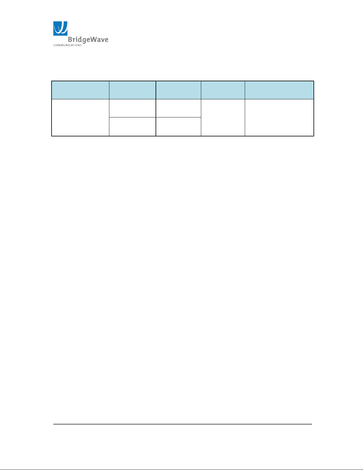
Table 1: FLEX4G-LITE Model
Additional configuration information is available in the FLEX4G-LITE Product
Description document available from BridgeWave or authorized
representative.
Page 15
Page 15 of 84
040-57105-01
3 Local Management Access
There are two methods of accessing local management features. The first method is
through the Web Graphical User Interface (GUI), and is the primary subject of this
document.
The second method is through a Command Line Interface (CLI). The CLI allows
access to some features that are not available through the Web GUI.
This document will explain how to access the radio through both methods, but will
only include command line details that are used in the initial configuration and basic
operation of the radio.
Tools and equipment needed to access and manage the
radio.
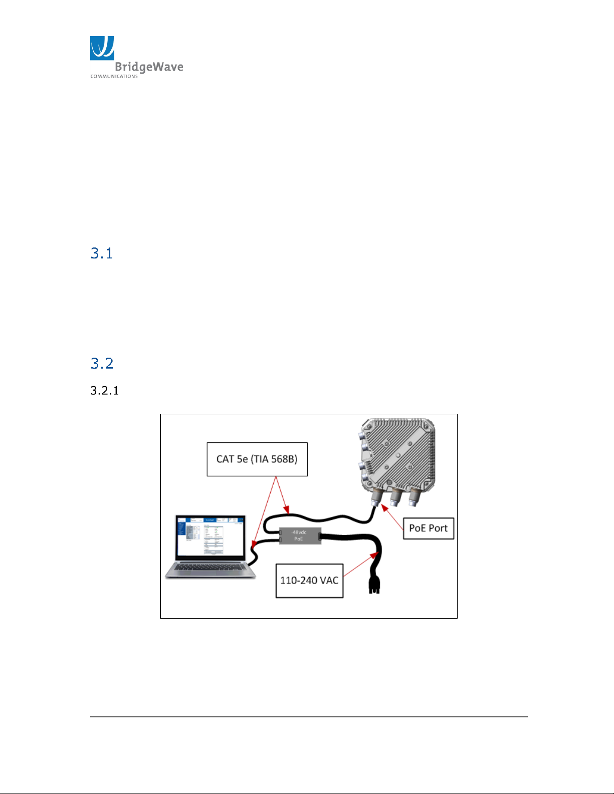
A PC or laptop with a web browser and telnet/ssh enabled
Use an Ethernet cable, TIA 568B pin out, to connect the PC to
the radio
Connection to FLEX4G-LITE
Connect the PC to any Ethernet port on the radio as shown in Figure 1
below
Figure 2: FLEX4G-LITE Power and Data Connection
Page 16
Page 16 of 84
040-57105-01
1
2
3
4 5 6
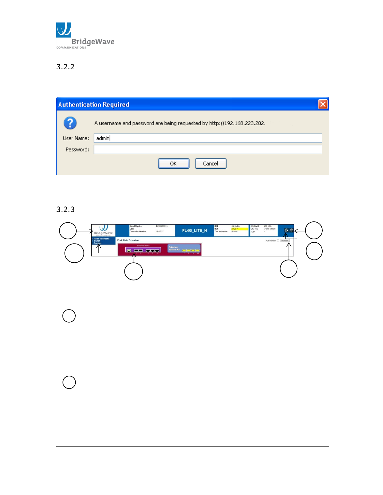
Open a browser on the PC and enter the default address of the radio in
the location bar. The default address for a Low Band Radio is
10.100.7.247, and for a High Band Radio it’s 10.100.7.248. Then press
“enter”, and the screen below will appear.
Figure 3: Main Login
Enter the username “admin”. There is no password required. Just hit
“enter”, and the following screen will open.
Figure 4: Main Window
1 Banner – This area Contains basic information about the radio and the
link. The first panel contains the serial number, Common Language
Location Indicator, and the Controller version. The second panel
contains the Receive Signal Level, the Bit Error Rate, and the Test
Indication. The third panel contains the Channel Bandwidth, and the
Channel Frequency.
2 Navigation Panel – This is the area where the various programmable
parameters can be selected. The parameters are divided into two main
categories, Radio and Switch. To view the parameters for each
category, click on the word, not the arrow next to it.
Page 17

Page 17 of 84
040-57105-01
3 Port State Overview – This item will appear when you first log into the
radio, and can also be accessed at any time by clicking on
Switch>Monitor>Port State. All other features in this section will appear
on every page.
Hover the mouse cursor over a port reveals its current state, and
clicking on a port will open another screen showing detailed port
statistics.
4 Log Out Button – Clicking on this will log you out of the radio and open
the login page.
5 Help Button – Clicking on this will open up a help window with help
categories for the page from which it is opened.
6 Refresh Button –Clinking on this button will refresh the current page.
Selecting on the Auto refresh box causes the current page to be
automatically refreshed at three seconds intervals. Clicking on it again
stops Auto-refresh.
Page 18
Page 18 of 84
040-57105-01
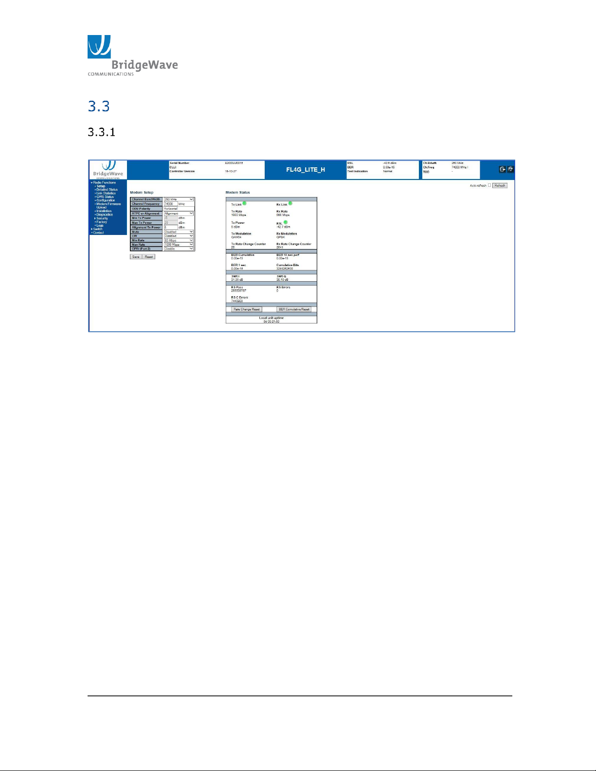
Figure 5: Radio Setup Page
Radio Setup
Click on Radio Functions>Setup in the Navigation Panel. The following
screen appears.
This page contains the panel where radio configuration changes can be made;
it also displays the current status of the modem and the link.
Please be aware that any changes that are entered are only made to the
radio, to which you are currently connected, and any changes made to
Frequency, Bandwidth, Mute, CW, or Data Rate will take down an operating
link until the same changes are made at the other end of the link.
Page 19

Page 19 of 84
040-57105-01
Channel Bandwidth: Pull down menu allows the user to select the
operating channel bandwidth, if licensed, from the pull down menu.
Channel Frequency: Input the Transmit Frequency in MHz for which this
radio is assigned. Valid frequencies must be divisible by 62.5MHz.
ODU Polarity: This field not configurable. However, the field will display the
current polarity the unit is on.
ATPC or Alignment: Select “ATPC” or “Alignment” from the next pull down
menu. “Alignment” should only be selected for use during the alignment
procedure as it will fix the transmit power per the value set in the Alignment
TX Power box. The radio must be set to ATPC after the link is properly
aligned for normal operation.
Min TX Power and Max TX Power: Enter the Minimum and Maximum
Transmit ATPC power levels. Allowable range is from -5 dBm to +22 dBm.
This feature only works with ATPC is selected.
Alignment Tx Power: Enter a specific transmit power value. This feature
only works when Alignment mode is selected.
Mute: Enable Mute to stop RF Transmission of the local radio. The Mute
Timeout value is configured under the Configuration page. The default
value is 10 mins.
CW: Disables transmitter modulation and sends a constant carrier out the
antenna port for tests requiring an unmodulated signal.
Minimum and Maximum Bit Rate: Selects the allowable minimum and
maximum bit rates from the pull down menus. This must be done in order for
Adaptive Coding and Modulation to operate. The maximum bit rate is
controlled by the license key installed on the Licensing page.
CPRI (Port 2): Select the CPRI speed from the pull down menu. The range
available is: 614.4Mbps – 3.072Gbps.
Setting the Radio’s IP Address
Radio IP Address can be changed by selecting the following link from
the Navigation pane:
Switch>Configuration>System>IP in the Navigation Panel.
This will open the following screen.
Page 20
Page 20 of 84
040-57105-01
Figure 6: IP Configuration Page
Note: The unit is preconfigured with a default IP address from the factory depending
on the unit type (Low Band or High Band). This address is associated with VLAN 1
which is also created at the factory during initial configuration. Using the “Factory
Defaults” page to revert the configuration will not change the IP address configured
by the customer. However, using the CLI command to default the unit will cause all
VLAN and IP information to be lost. Unless the “keep IP” option is use, a new VLAN
and IP address will have to be configured via the serial port.
Also, saving the changes by clicking on the “Save” button will not keep the new
settings unless the startup-config is saved. This is done by navigating to the “Save
startup-config” page using the following link:
Switch>Maintenance>Configuration>Save startup-config
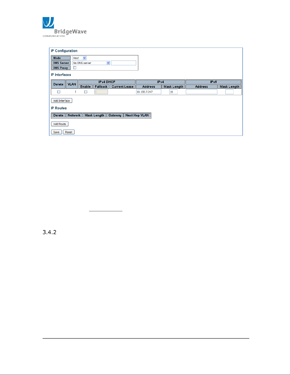
This page is divided into three sections; IP Configuration, IP Interfaces,
and IP Routes. Once all changes have been made, click the “Save”
button before proceeding to another page.
IP Configuration: This section allows for the configuration of the unit to act as
a Host (default setting) or router. It also allows for the configuration of the
DNS server.
Mode: Host mode, IP traffic between interfaces will not be routed. Router
mode traffic is routed between all interfaces.
DNS Server: This setting controls the DNS name resolution done by the
switch.
From any DHCP interfaces: The first DNS server offered from a DHCP –enable
interface will be used
No DNS server: No DNS server will be used (default setting).
Page 21

Page 21 of 84
040-57105-01
Configured: Explicitly provide the IP address of the DNS Server in dotted
decimal notation
From this DHCP interface: Specify from which DHCP-enabled interface a
provided DNS server should be preferred
o DNS Proxy: When DNS proxy is enabled, system will relay DNS
Request to the currently configured DNS server, and reply as a DNS resolver
to the client devices on the network.
IP Interfaces: Configured IP interface with the use of either IPv4 or IPv6.
The default interface is VLAN 1 with IP address of 10.100.7.247 for the Low
Band radio and 10.100.7.248 for the High Band radio.
The configurable fields in this section are:
Delete: Select this option to delete an existing IP interface
VLAN: The VLAN associated with the IP interface. Only ports in this VLAN
will be able to access the IP interface. (This field is only available for input
when creating a new interface.)
IPv4 DHCP Enable: Enable the DHCP client by checking this box. If this
option is enabled, the system will configure the IPv4 address and mask of
the interface using the DHCP protocol. The DHCP client will announce the
configured System Name as hostname to provide DNS lookup.
IPv4 Fallback: The number of seconds for trying to obtain a DHCP lease.
After this period expires, a configured IPv4 address will be use as IPv4
interface address. A value of zero disables the fallback mechanism, such
that DHCP will keep retrying until a valid address is obtained. Range
values are 0 to 4294967295 seconds
IPv4 Address: IPv4 address of the interface is dotted decimal notation.
(If DHCP is enabled, this field configures the fallback address. The field
may be left blank if IPv4 operation on the interface is not desired – or no
DHCP fallback address is desired.)
IPv4 Mask: The IPv4 network mas, in number of bits (prefix length).
Valid values are between 0 and 30 bits for an IPv4 address. (If DHCP is
enabled, this field configures the fallback address network mask. The field
may be left blank if IPv4 operation on the interface is not desired – or no
DHCP fallback address is desired.)
IPV6 Address: The IPv6 address of the interface. An IPv6 is in 128-bit
records represented as eight fields of up to four hexadecimal digits with a
colon separating each field (:). For example, fe80::215:c5ff:fe03:4dc7.
The symbol “::” is a special syntax that can be used as a shorthand way of
representing multiple 16-bit groups of contiguous zeros; but it can appear
Page 22

Page 22 of 84
040-57105-01
only once. It can also represent a legally valid IPv4 address. For example,
::192.1.2.34. The field may be left blank if IPv6 operation on the interface
is not desired.
IPv6 Mask: The IPv6 network mask, in number of bits (prefix length).
Valid values are between 1 and 128 bits for an IPv6 address. The field
may be left blank if IPv6 operation on the interface is not desired.
IP Routes: This section is use to configured the routing options for the IP
interfaces configured. The configurable fields for this section are:
Delete: Select this option to delete an existing IP route
Network: The destination IP network or host address of this route. Valid
format is dotted decimal notation or a valid IPv6 notation. A default route
for IPv4 is configured using 0.0.0.0 . A default route for IPv6 is configured
using “::” notation.
Mask Length: The destination IP network or host mask, in number of bits
(prefix length). It defines how much of a network address that must
match, in order to qualify for this route. Valid values are between 0 and
32 bits respectively 128 for IPv6 routes. Only a default route will have a
mask length of 0 (as it will match anything).
Gateway: The IP address of the IP gateway. Valid format is dotted
decimal notation or a valid IPv6 notation. Gateway and Network must be
of the same type.
Next Hop VLAN(Only for IPv6): The VLAN ID (VID) of the specific IPv6
interface associated with the gateway. The given VID ranges from 1 to
4094 and will be effective only when the corresponding IPv6 interface is
valid. If the IPv6 gateway address is link-local, it must specify the next
hop VLAN for the gateway. If the IPv6 gateway address is not link-local,
system ignores the next hop VLAN for the gateway.
Radios Default IP configuration
The unit will configured with the following default settings:
Low Band Unit: Mode: Host
IP address: 10.100.7.247
Mask Length: 24
IP Route: None
High Band Unit: Mode: Host
IP address: 10.100.7.248
Page 23
Page 23 of 84
040-57105-01
Mask Length: 24
IP Route: None
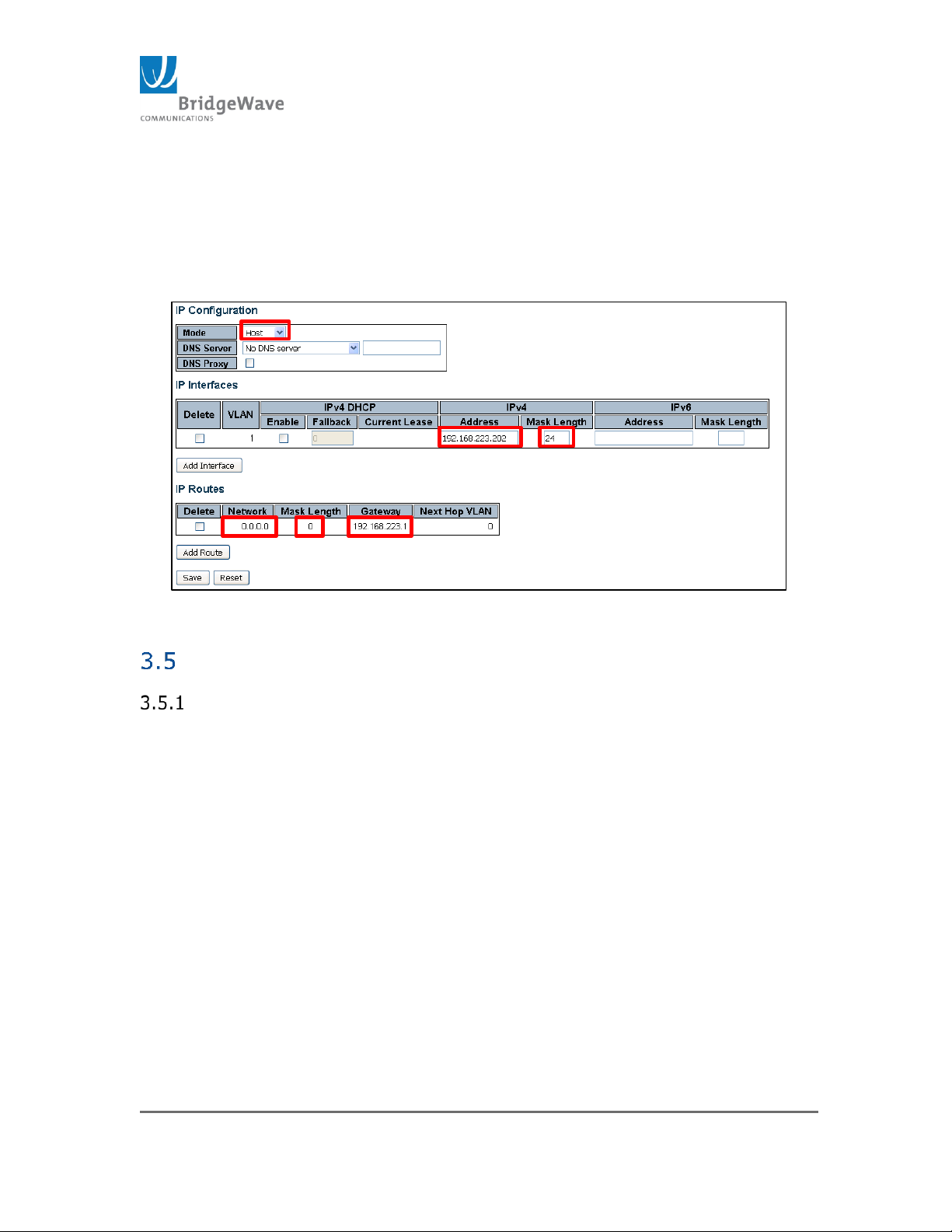
NOTE: In order for the configuration interface (host) to be reach from outside
the subnet, a default gateway needs to be configured. The following example
illustrates a unit configured to the 192.168.223.XXX subnet with outside
subnet communication:
Figure 7: Sample Host IP Configuration
Detailed Status Page
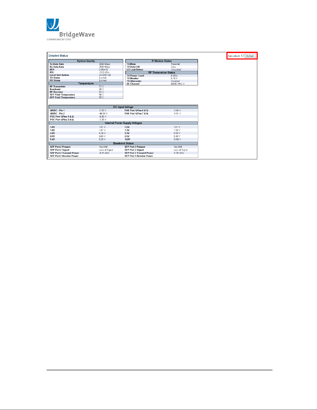
Select from the navigation pane Radio Functions>Detailed Status in
opens the following screen.
Page 24
Page 24 of 84
040-57105-01
Figure 8: Detailed Status Page
The Detailed Status page is an information page only. The page contains a “Refresh”
button to update the page and it also has an “Auto-refresh” select box to refresh the
page at one second intervals.
The page is divided into seven sections: System Quality, Temperature, IF Modem
Status, RF Transceiver Status, DC Input Voltage, Internal Power Supply Voltages, &
Baseband Status.
System Quality: The System Quality Panel displays the current TX and RX
data rates as well as the current Bit Error Rate (BER) and Receive Signal Level
(RSL). If the link is not yet aligned, or the far end transmitter is disabled, the
RSL will read below -70 dBm. This section also includes the Local Unit Uptime,
the current Tx and Rx status
Temperature: The Temperature section panel displays the RF Transmitter,
baseband board and RF Receiver temperatures as well the SFP temperatures
for both Port 2 and Port 3 (These values are only available when an SFP
module is inside the SFP cage).
IF Modem Status: The IF Modem section displays information related to the
state of the transmitter. The transmitter can be set to “Transmit” “Mute”
and/or “CW”. It also sates whether the Local Oscillator (LO) is locked. If the
LO is Unlocked, this indicates a transmitter failure and the ODU will require
replacement
RF Transceiver Status: The RF Transceiver Status displays the current Tx
power level, the Tx Monitor voltage, the setting of the Tx Attenuator, (Enabled
or Disabled), and the Tx channel setting. By default, the Tx Attenuator will be
“Disable”. The Tx Monitor voltage range is between 0v and 1v. This value
changes the Tx Output power. 0v indicates a possible failure in the
transmitter.
Page 25

Page 25 of 84
040-57105-01
DC Input Voltage and Internal Power Supply Voltages: These panels display
the various specified internal operating voltages in bold print and the actual
voltage in normal print. Under the DC Input Voltage panel, only the port or
ports with actual power input will display true values. Any of the ports with no
input will display non-real values.
Baseband Status: The Baseband Status panel displays they type of SFP
modules that are currently installed in the unit as well as basic information
regarding their status.
Page 26
Page 26 of 84
040-57105-01
Link Statistics Page
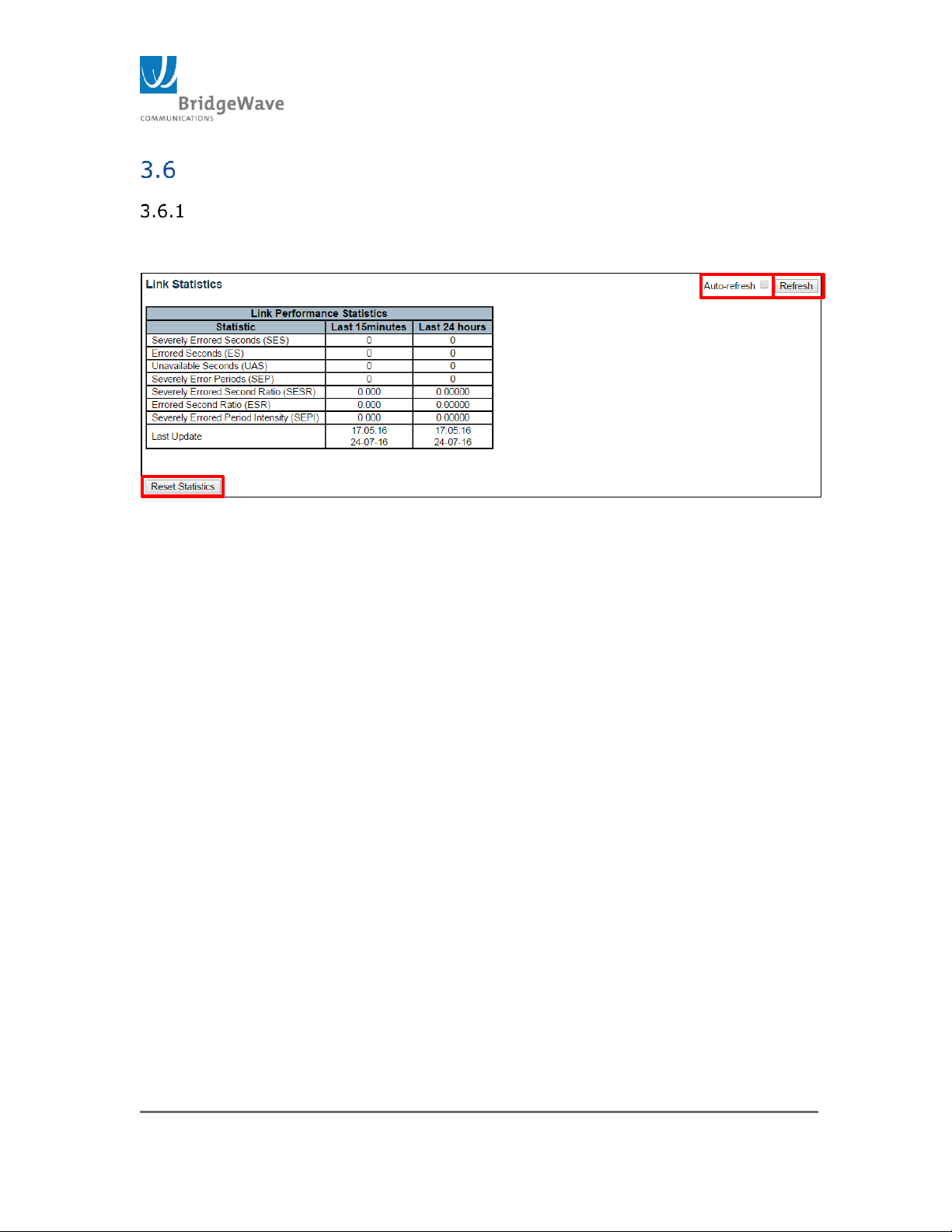
Selecting from the navigation pane Radio Functions>Link Statistics
opens the following screen.
Figure 9: Link Statistics Page
This page will display different type of errors. It also contains two buttons:
Refresh and Reset Statistics as well as an “Auto-refresh” select box. When
this box is selected, the statistics will update in one second intervals. The
errors reported on this page are related to the wireless link only. These are
errors that have occurred within the last 15 minutes as well as the last 24hrs.
The last line reports the date and time when the “Last Update” was reported.
Statistics Description:
Severely Errored Seconds (SES): Number of seconds where the link
had greater than 30% errored blocks for that second.
Errored Seconds (ES): Number of seconds where the link had one or
more errored blocks for that second.
Unavailable Seconds (UAS): Number of seconds where the link was
out of service.
Severely Error Periods (SEP): Number of periods that there were 3
to 9 consecutive SES seconds.
Severely Errored Second Ratio (SESR): Ratio of Severely Errored
Seconds to the total number of seconds in the time period.
Errored Second Ratio (ESR): Ratio of Errored Seconds to the total
number of seconds in the time period.
Severely Errored Period Intensity (SEPI): The number of SEP
events in the period divided by the total seconds in the time period.
Page 27
Page 27 of 84
040-57105-01
Last Update: Time and Date of the last update.
Configuration Page
Selecting from the navigation pane Radio Functions>Configuration
opens the following screen.
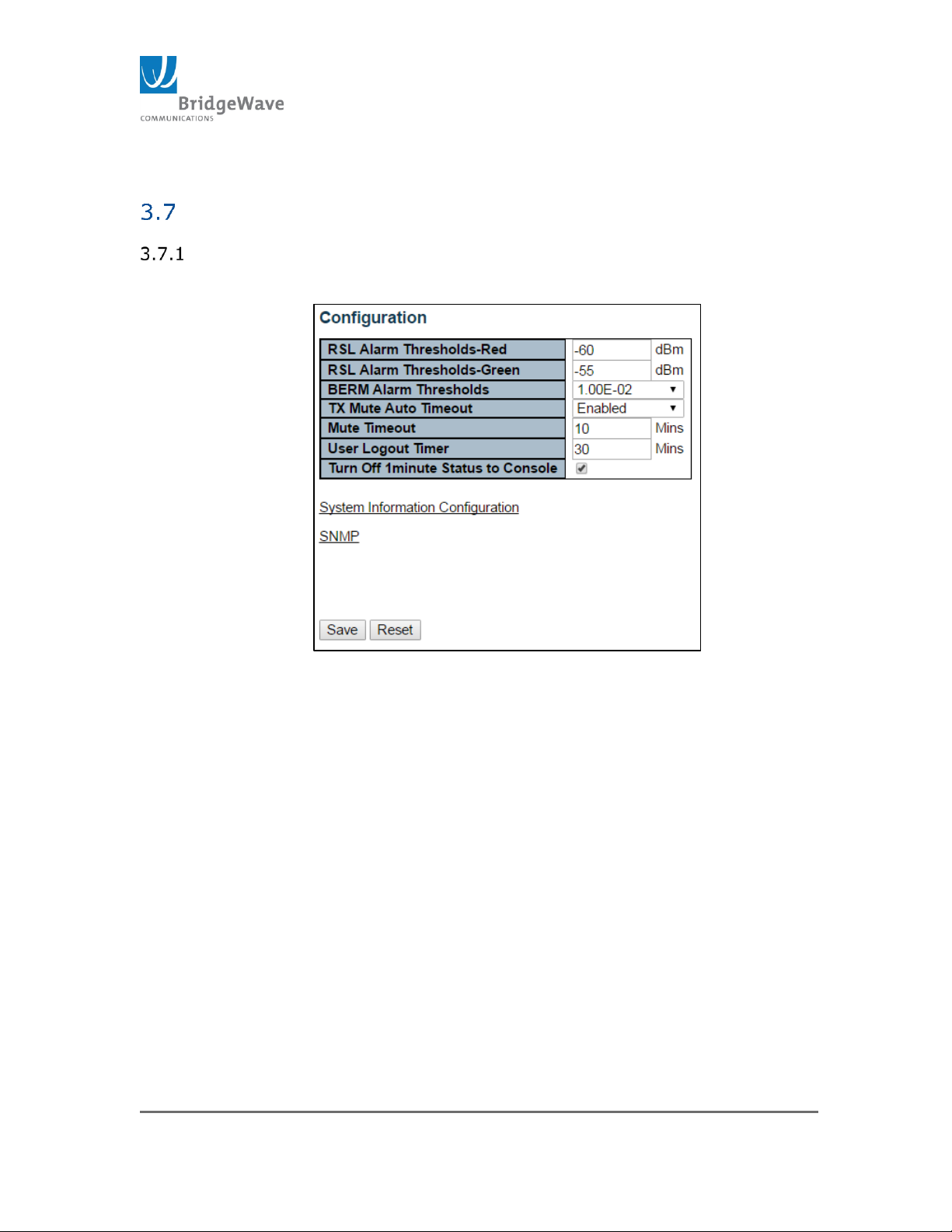
Figure 10: Configuration Page
This page allows the configuration of Alarm Thresholds, Tx Mute options as
well as access to other relevant pages. These parameters are described with
more detail in the following section.
Alarm Thresholds:
RSL Alarm Threshold-Red: Default value -60 dBm. If the signal falls
below this value, an alarm will be trigger as well as the indicator will
turn red on the Modem Status, under the Setup page. The acceptable
input range is from -80dBm to -20dBm.
NOTE: The RSL indicator will change to Yellow when the RSL is
between the RSL Alarm threshold Red and RSL Alarm threshold Green.
RSL Alarm Threshold-Green: Default value -55 dBm. The RSL Level
at which the radio will alarm, causing the RSL Indicator display to
change from Red to Green. The RSL value must be greater than the
Green threshold value. The acceptable range is from -80dBm to 20dBm.
Page 28
Page 28 of 84
040-57105-01
BERM Alarm Thresholds: This is the Bit Error Rate value at which the
radio BERM alarm is set. The alarm will report to the system log and if
the SNMP Trap function is enabled, it will send the BERM trap. This
value is set using a pull down menu. Available options are 1.00E-02 to
1.00E-10.
Tx Mute Auto Timeout: This control sets the time interval after which
the Tx Mute or CW feature will automatically be disabled. This value is
set via a pull down menu. Available options are Enable & Disable. The
default setting is “Disabled”.
Mute Timeout: This control allows the interval in minutes, of the Tx
Mute Auto Timeout. The Tx Mute Auto Timeout feature must be
“Enabled” via the pull down menu first. The maximum value that can
be set is 120 minutes.
User Logout Timer: This control sets the time interval after which a
CLI user will be logged out automatically if no activity is detected. The
time is set in minutes with a maximum value of 120 minutes. This
feature will not be set until the Save button is clicked.
Turn Off 1 minute Status to Console Port: This checkbox when
selected, turns off the 1 minute periodic radio status report sent to the
console port. If the Checkbox is unchecked, the 1 minute status report
is sent to the console.
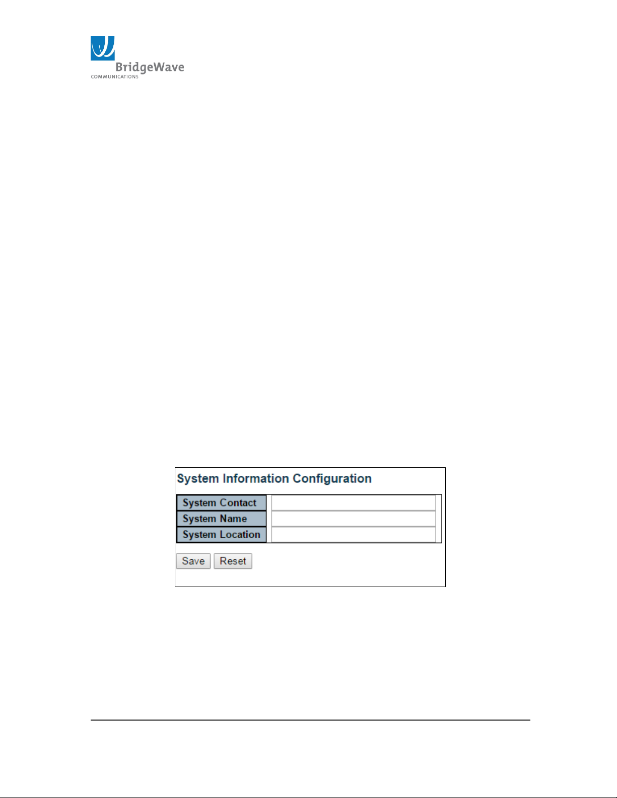
System Information Configuration: This hyperlink provides quick
access to the System Information Configuration page.
Figure 11: System Information Configuration
The textual identification of the contact person for this managed
unit, together with information how to contact this person. The
allowed string length is 0 to 255, and the allowed content is the
ASCII characters from 32 to 126.
Page 29
Page 29 of 84
040-57105-01
Note: the System Name field does not allow spaces or special characters,
only alphanumeric characters.
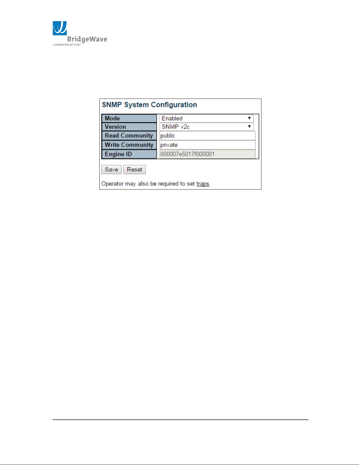
SNMP: This hyperlink provides quick access to the SNMP configuration
page.
Figure 12: SNMP System Configuration
This page allows the configuration of SNMP.
Mode: Enable/Disable
Version: SNMPv1/SNMPv2c/SNMPv3
Read Community: Indicates read string to permit access to SNMP
agent. The allowed string length is 0 to 255 characters, and the
allowed content is the ASCII characters from 33 to 126.
NOTE: The field is applicable only when SNMP version v1 and v2c.
SNMPv3’s community string will be associated with the communities
table. If provides more flexibility to configure security name than version
v1 and v2c community string. In addition to community string, a
particular range of source addresses can be used to restrict source
subnet.
Wire Community: Indicates write string to permit access to SNMP
agent. The allowed string length is 0 to 255 characters, and the
allowed content is the ASCII characters from 33 to 126.
NOTE: The field is applicable only when SNMP version v1 and v2c.
SNMPv3’s community string will be associated with the communities
table. If provides more flexibility to configure security name than version
v1 and v2c community string. In addition to community string, a
particular range of source addresses can be used to restrict source
subnet.
Page 30
Page 30 of 84
040-57105-01
Engine ID: Indicates the SNMPv3 engine ID. The string must contain
an even number (in hexadecimal format) with number of digits
between 10 and 64, but all-zeros and all-F’s are not allowed. Change
of the Engine ID will clear all original local users.
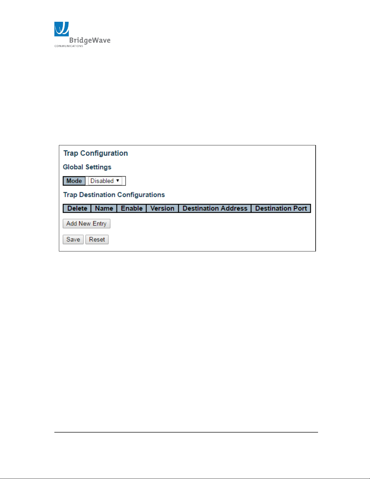
Traps: This hyperlink provides quick access to the SNMP Trap
configuration page.
Figure 13: Trap Configuration Page
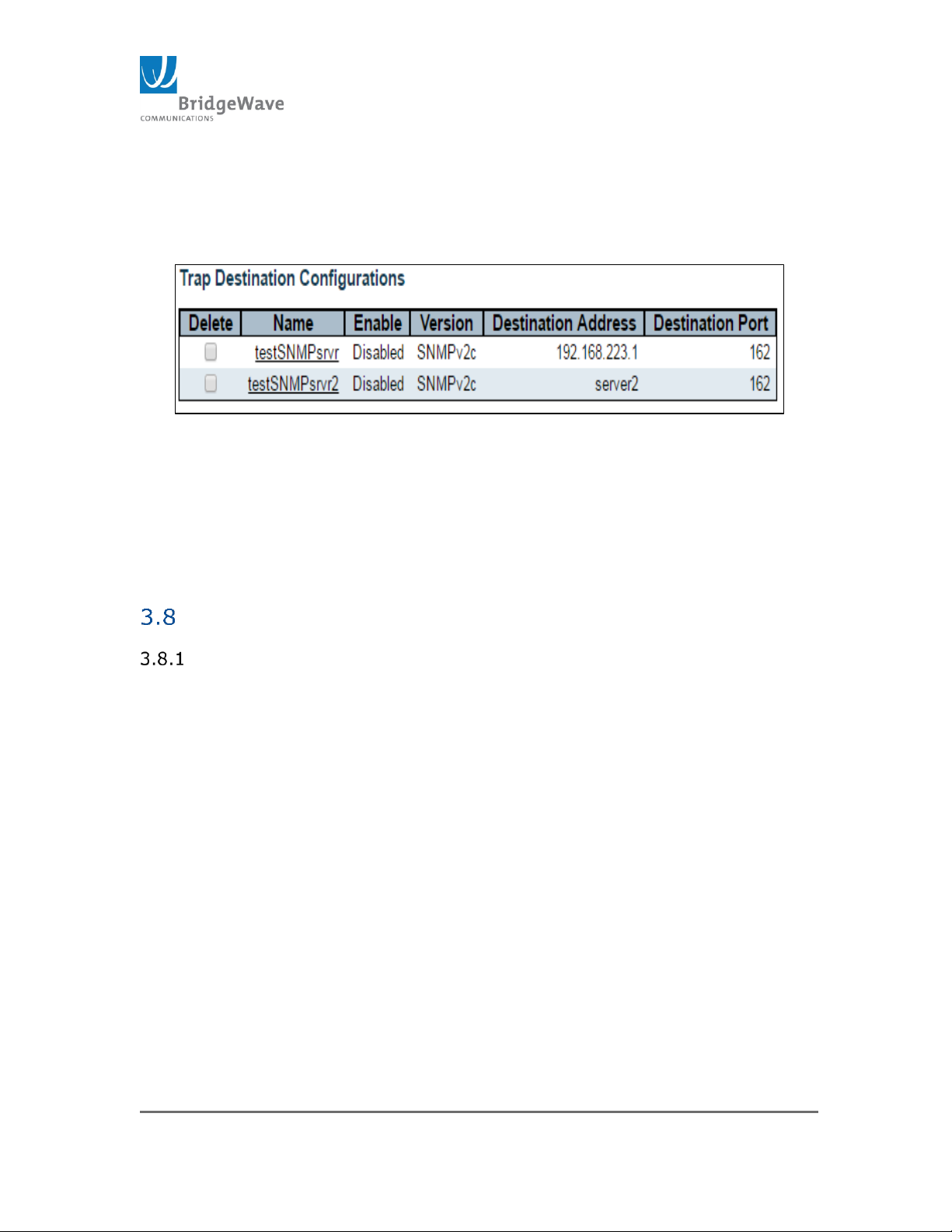
This page allows for the configuration of SNMP traps.
Mode: Enable/Disabled
Delete: Selecting this checkbox will delete the Trap Destination entry
once the “Save” button is click
Name: Indicates the trap Destination Configuration’s name
Enable: Indicates if that specific entry is either on or off
Destination Address: Indicates the SNMP trap destination address. It
displays an IP address in dotted decimal notation (1.1.1.1). It also
allows a valid hostname.
NOTE: A valid hostname is a string drawn from the alphabet (A-Za-z),
digits (0-9), dot (.), dash (-). Spaces are not allowed, the first character
must be in alpha character, and the first and last characters must not be a
dot or a dash.
Page 31
Page 31 of 84
040-57105-01
Destination Port: Indicates the SNMP trap destination port. The SNMP
agent will send SNMP messages via this port. The valid port range is 1
– 65535.
Figure 14: Trap Configuration Example
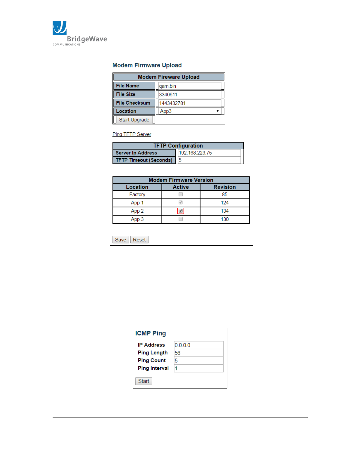
Modem Firmware Version: This table displays the Modem/FPGA
revision residing at each memory location identified as Factory, App 1,
App 2, and App 3. Selecting one of the fields and saving the
configuration will result in the unit switching to the Modem Firmware
Version residing in the memory location selected.
Modem Firmware Upload Page
Selecting from the navigation pane Radio Functions>Modem Firmware
Upload opens the following screen
Page 32
Page 32 of 84
040-57105-01
Figure 15: Modem Firmware Upload Example
Note: In the above example, field App 2 was selected, once the “Save”
button is click, the unit will switch from the version residing in field App 1 to
the version residing in field App 2.
Modem Firmware Upload section is explained in detail in section
5
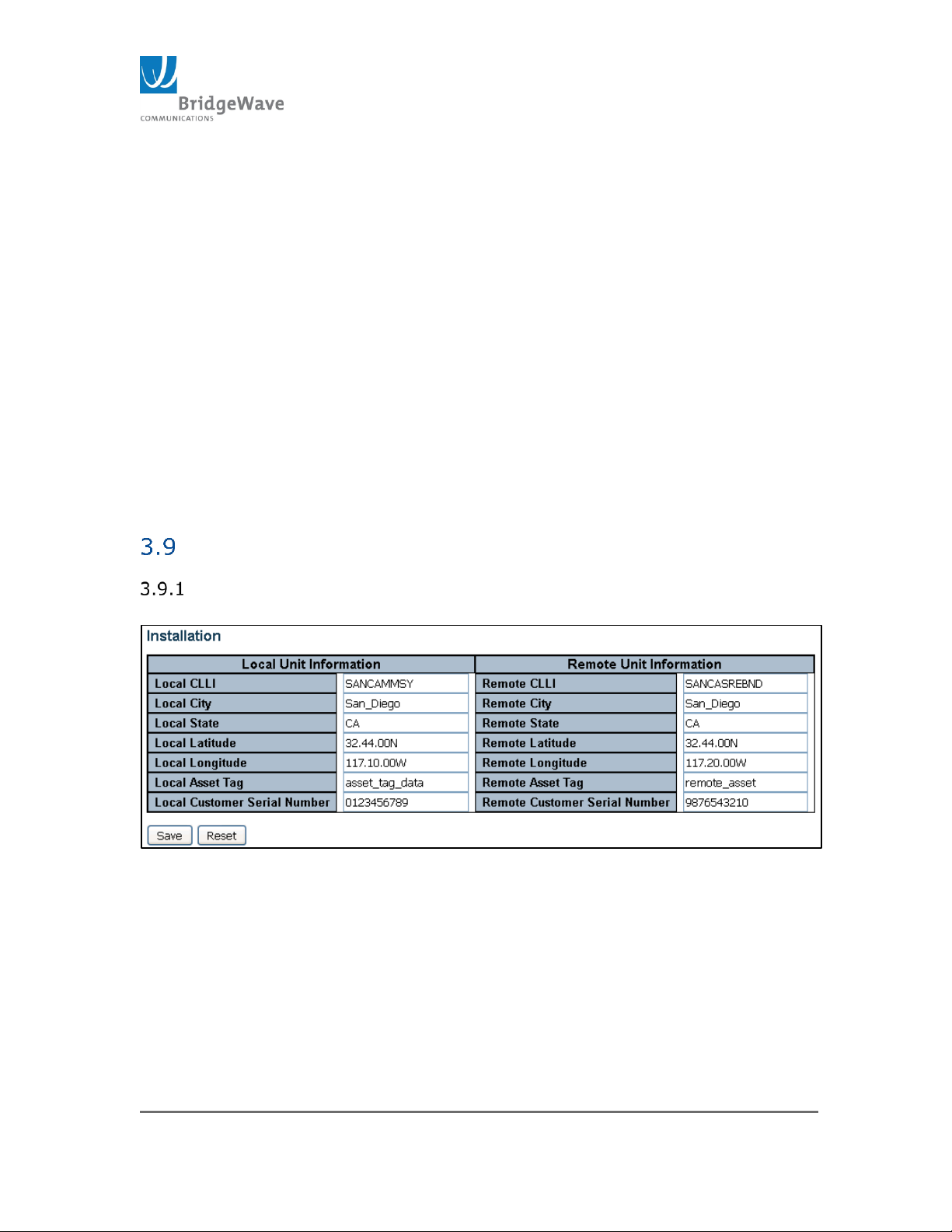
Pint TFTP Server: This hyperlink will open a sub-window that will
allow to ping the IP address of the TFTP server:
Figure 16: Ping TFTP Server
Page 33
Page 33 of 84
040-57105-01
NOTE: This page can also be used to ping any other IP address.
TFTP Server IP: This field sets and displays the current TFTP server
address for TFTP transfers.
TFTP Timeout: This field sets the time interval for the TFTP timeout in
seconds, with fixed retry count resulting in timeout (6-30 seconds).
The “Save” button, must be click before any configuration changes will
take effect.
The “Reset” button, will reset the page back to the configuration
before any changes were made. Only if the “Save” button has not been
executed.
Installation Page
Selecting from the navigation pane Radio Functions>Installation opens
the following screen
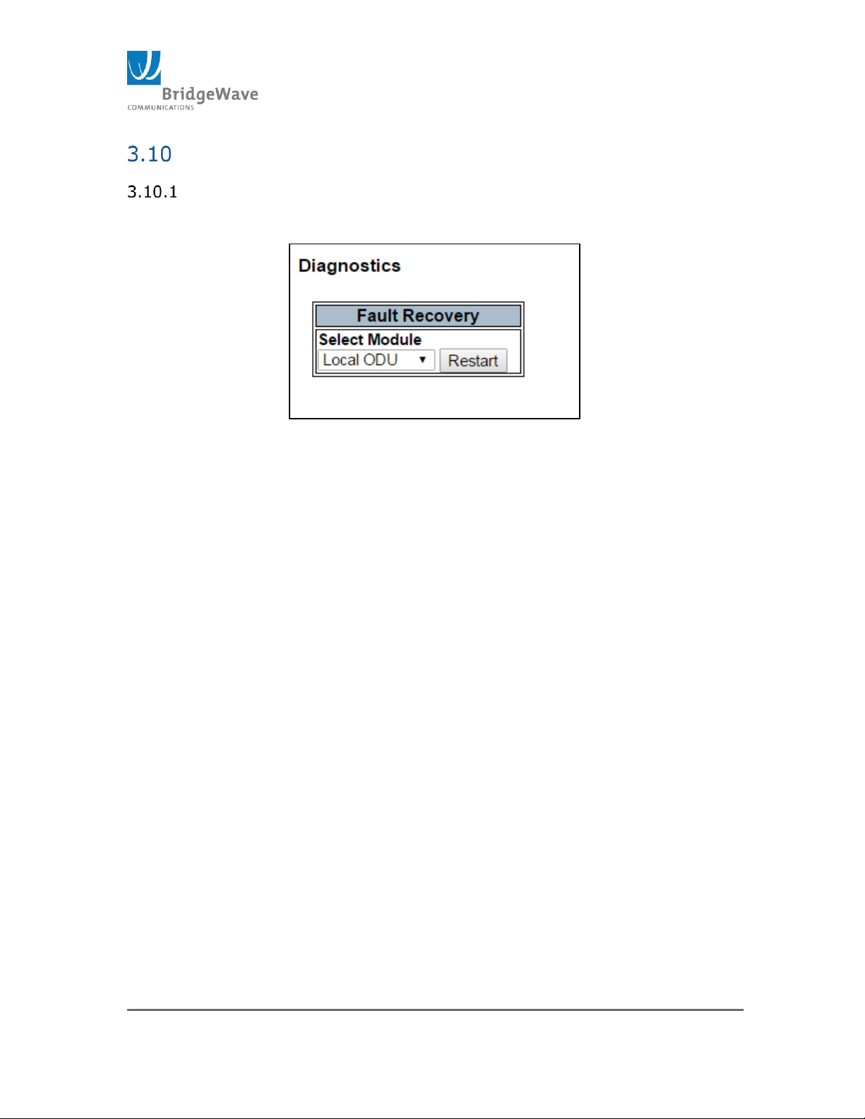
Figure 167: Installation Pages
This page is for information only and does not affect the operation of the
radio. These are two columns; one column for information on the Local Radio
and a second column for the same type of information on the Remote Radio.
Both columns require the information to be manually inputted.
The information that can be entered here is as follows:
CLLI : Common Language Location Indicator
City: City where radio is installed
State: State where radio is located
Page 34

Page 34 of 84
040-57105-01
Latitude: of site where radio is located.
Longitude: of site where radio is located.
Asset Tag: of radio if one is assigned
Customer Serial Number: This field is used by the FLEX4G-LITE.
Page 35
Page 35 of 84
040-57105-01
Diagnostics Page
Selecting from the navigation pane Radio Functions>Diagnostics opens
the following screen
Figure 178: Diagnostic Page / Fault Recovery
The purpose of this page is to restart the radio as may be required for fault
recovery.
Fault Recovery, Select Module:
o Local ODU – Select this module to restart the UI software.
o Local Modem - Select this module to restart the modem/FPGA
Note: Restarting either device module will interrupt traffic over the
link.
Page 36
Page 36 of 84
040-57105-01
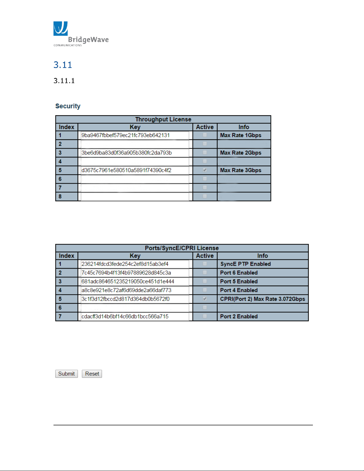
Security Page
Selection from the navigation pane
Radio Functions>Security>Licensing will open the following screen.
Figure 189: Security Licensing Page
Page 37
Page 37 of 84
040-57105-01
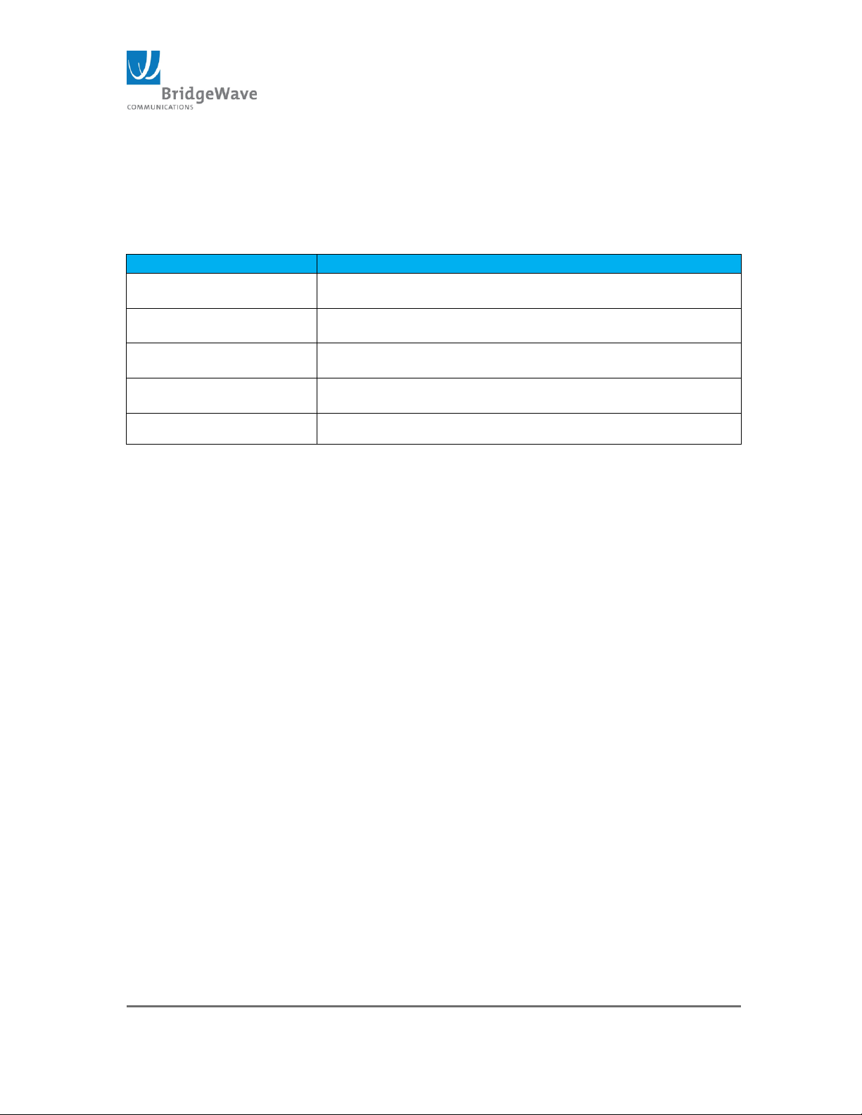
License
License Description
FL4G-LITE-UPG-1G-2G
Adaptive Modulation and Rate License from 1000 Mbps to
2000Mbps
FL4G-LITE-UPG-1G-3G
Adaptive Modulation and Rate from 1000 Mbps to
3000Mbps
FL4G-LITE-UPG-2G-3G
Adaptive Modulation and Rate from 2000 Mbps to
3000Mbps
FL4G-LITE-UPG-SYNC
Software upgrade with Precision Timing Protocol (PTP):
SyncE and 1588v2
FL4G-LITE-CPRI
CPRI Firmware License for 2.458 Gbps
This page is where Rate, Ports 2-6, SyncE and CPRI Licensing codes are entered. If
the link is purchased with less than the maximum capacity, a license for additional
capacity can be purchased from your BridgeWave Sales representative.
Licenses are available for the following throughputs:
Table 2: Available FLEX4G-LITE Adaptive Rate Licenses
Note: To increase the capacity after purchasing a new license, enter the Throughput
key and/or SyncE/CPRI key supplied with the license in the first blank row of the
corresponding table, Throughput or SyncE/CPRI License, and click on Submit. If the
key is valid the new maximum rate and/or allowed SyncE/CPRI will display in the info
column. Active Column with Check box marked indicates which License Key is active
for Throughput and CPRI date rates; if the Check box is marked, it indicates the
License Key not active or invalid.
Also, note that the license will not take effect until an ODU restart has occurred.
Page 38
Page 38 of 84
040-57105-01
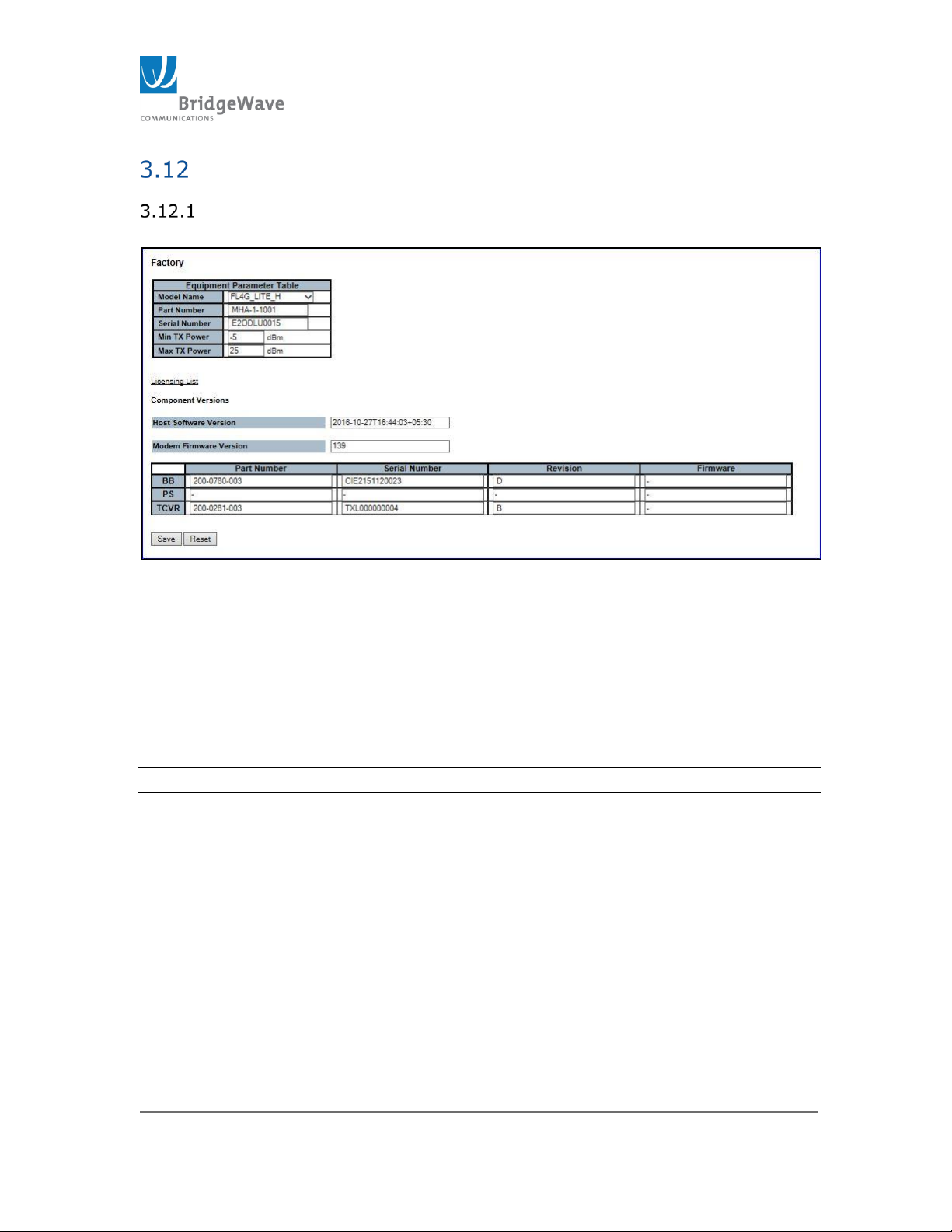
Factory Page
Selecting from the navigation pane Radio Functions>Factory will open
the following screen.
Figure 20: Factory Page
This page is for factory use only. Technical Bulletins will be issued with
specific instructions for applicable features on this page. It is recommended
not to change any values listed on this page.
Equipment Parameter Table: This table allows the factory to entered
Model Name, Part Number, Serial Number, Min Tx Power and Max Tx
power.
NOTE: Do not make any change unless recommended by product support.
Licensing List: This hyperlink provides quick access to the License
List of Security Page
Component Version: This section provides read-only information on
the version of current Software and FPGA revision, which includes:
Host Software Version: Current build image details with date and
time.
Modem Firmware Version: Active FPGA Slot Revision. Refer to the
Configuration Page to change to an alternative FPGA revision.
Page 39
Page 39 of 84
040-57105-01
Table with details on the Part Number, Serial Number, Revision
and Firmware for Baseband/Power Supply/Transceiver.
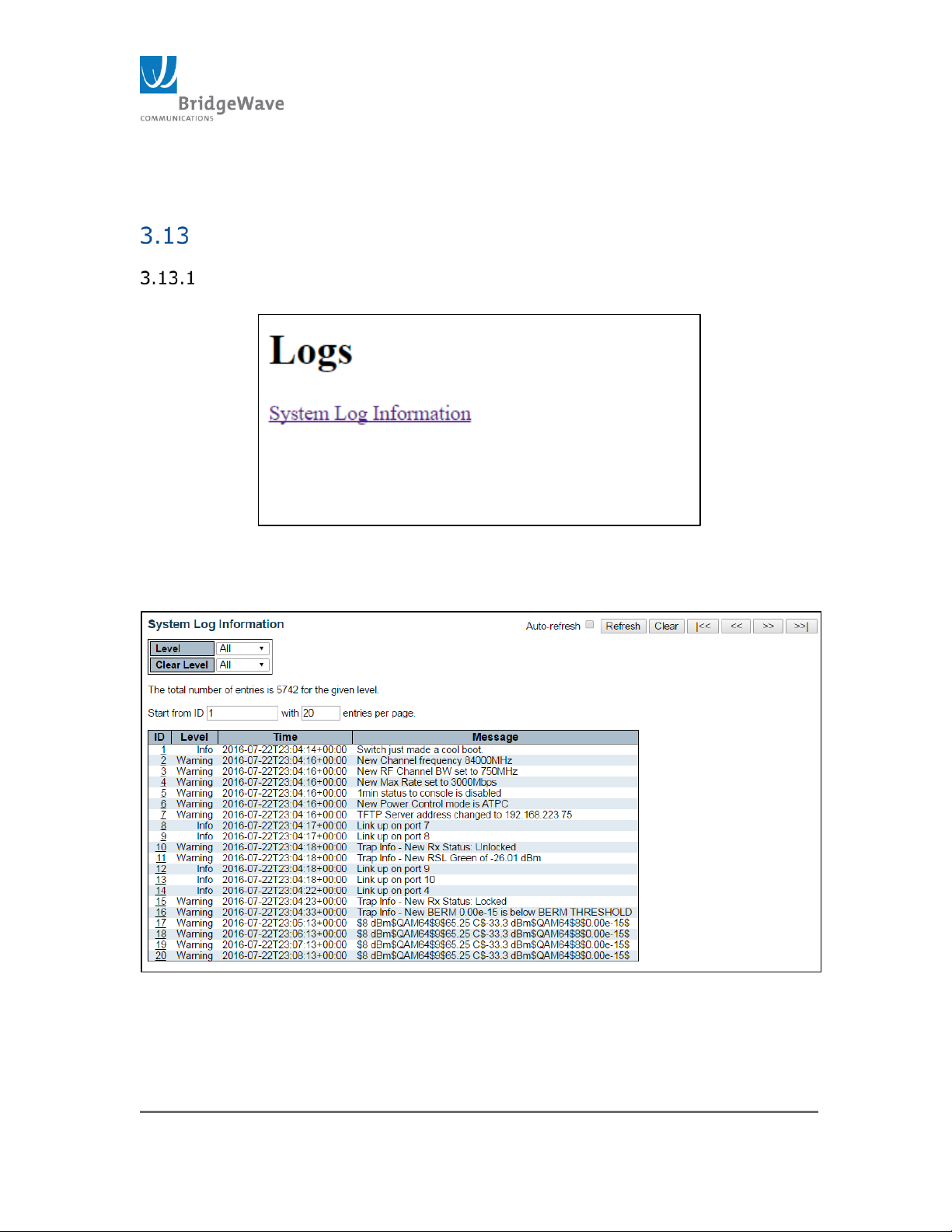
Logs Page
Selecting from the navigation pane Radio Functions>Logs will open the
following screen.
Figure 191: Log Hyperlink Page
The only option on this page is to select System Log Information hyperlink. Once
clicked, the System Log Information page will display
Figure 20: Log Page
This page displays the event and performance history log. Under System Log
Information there are two pull down menus.
Page 40
Page 40 of 84
040-57105-01
Level: This field is used to filter the display system log entries. The following
options are allowed:
Info
Warning
Error
All (Default)
Clear Level: This field is used to specify which system long entries will be
cleared. The following options are allowed:
Info
Warning
Error
All (Default)
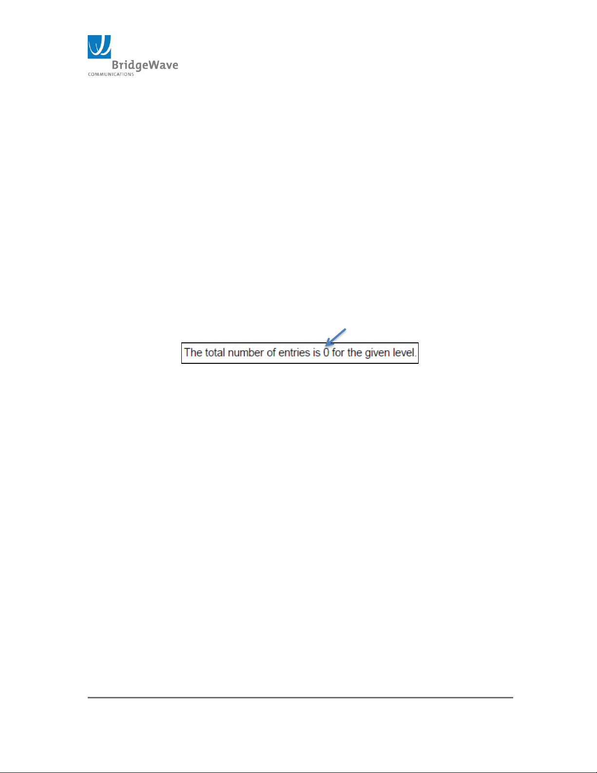
The total number of log entries is stated immediately under the pull down
menus.
Figure 213: Total System Log Entries
The “Start from ID” input field allows the user to change the starting point in this
table. The “with” box allows the number of entries per page to define.
The System Log Information Entry Columns are defined as follows:
ID: The identification of the system log entry.
Level: The level of the system log entry. The types of level were defined
above under the “Level” bullet.
Time: The occurred time of the system log entry.
Message: The detail message of the system log entry.
The Periodic Status Message format shown in Figure 20 can be decoded as:
$8 dBm $ Current Tx_Power level
$64QAM$ Current tx_modulation Constellation setting
$9$ Number of times the Transmitter changed modulation states
since last user reset
$65.25C$ RF_temperature (internal in the ODU)
$-33.3 dBm Receive Signal level in dBm
$QAM64$ Current Receiver Demodulation Constellation
$8$ Number of times the Receiver changed modulation states
since last user reset
$ 0.00e-15$ Receiver BER during the last 1min interval
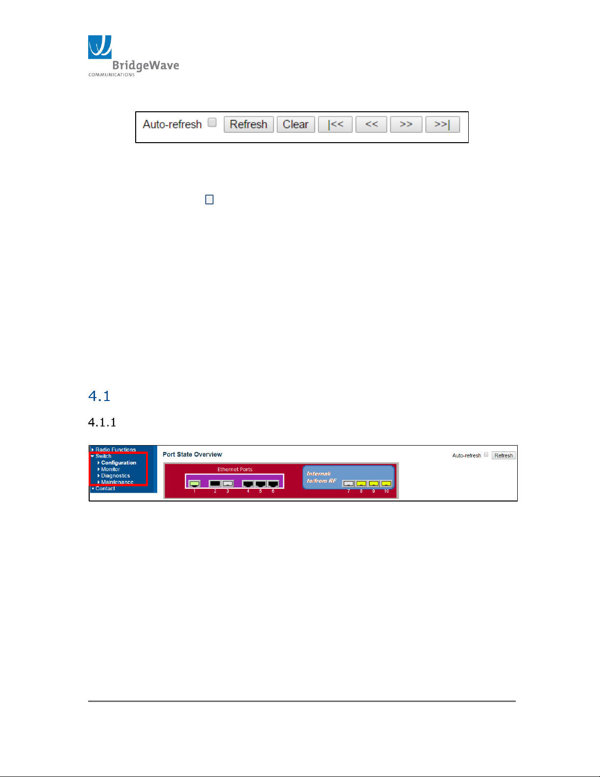
This page also contains utility buttons to manipulate the System log display.
Page 41
Page 41 of 84
040-57105-01
Figure 224: System Log Information Buttons
This buttons are defined as follows:
Auto-refresh : Check this box to refresh the page automatically.
Automatic refresh occurs every 3 seconds.
Refresh: Updates the table entries, starting from current entry.
Clear: Flushes the selected entries.
|<<: Updates the table entries, starting from the first available entry.
<<: Updates the table entries, ending at the last entry currently
displayed.
>>: Updates the table entries, starting from the last entry currently
displayed.
>>|: Updates the table entries, ending at the last available entry.
4 FLEX4G-LITE – Switch Functions
Switch Menu Options
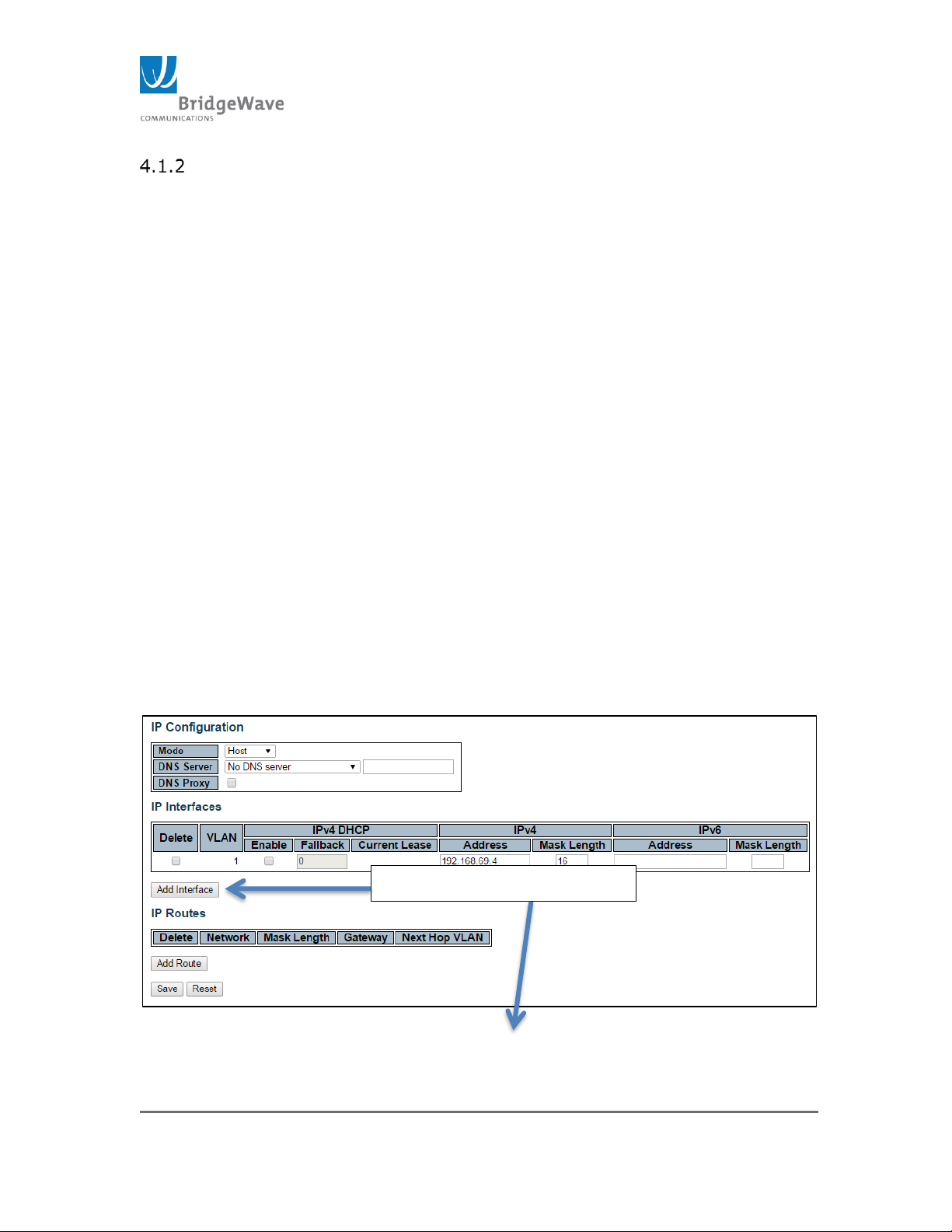
Selecting from the navigation pane Switch>
Figure 235: Switch Submenu Options
The Switch menu options include:
Configuration: The configuration of the radio’s switch is implemented
under these pages
Monitor: To view statistics as well configuration pages of the switch
Diagnostics: Introduces some tools to assist on troubleshooting
switch issues
Maintenance: Allows the restart, default and new software updates
and configuration upload.
Page 42
Page 42 of 84
040-57105-01
Click to add new VLAN
Configuration
The configuration submenu has all the pages required to adjust the radio’s switch to
meet most applications required by today’s network standards. The many different
menu options will not be covered by the manual. However, the required parameters
and functions that will allow the radio’s switch to be integrated into most basic
networks will be cover by this manual.
System
Access to this pages: Switch> Configuration>System>
The system configuration submenu provides access to the following pages:
Information: This page contains System Contact, System Name
and System Location.
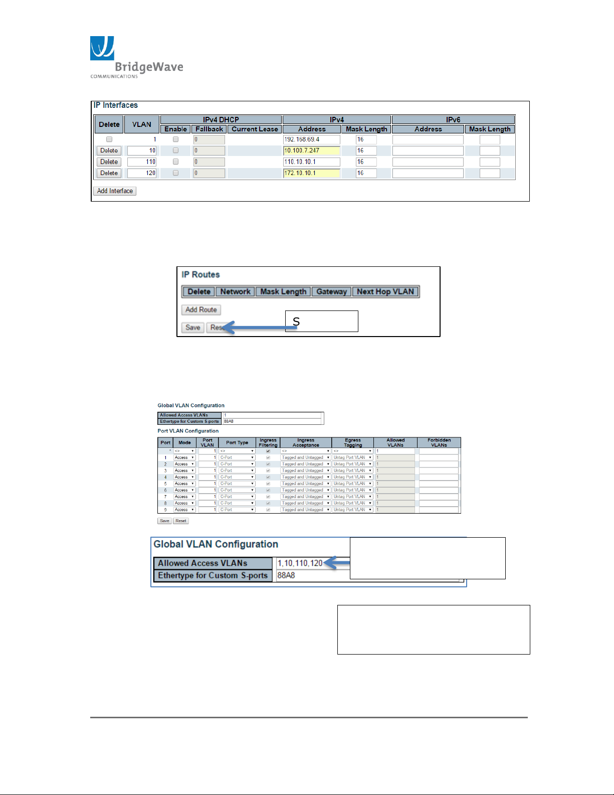
IP: This page contains the configuration required to access the
unit’s management interface via an IP address. Each IP address is
fixed to a specific VLAN ID. This allows for the configuration of
multiple IP address in different subnets, in different VLANs. The
default Mode configuration is “Host”. If the mode is change to
“Router”, the unit will allow routing between the different VLANs
configured. The following steps described the process of creating
multiple management interfaces using different VLANs.
1. Add or created the different VLAN interfaces and configured
unique IP to each.
Access this page: Switch>System>IP
Page 43
Page 43 of 84
040-57105-01
Save New
Entered new VLAN IDs to
allow them access
Ports 4, 5 and 6 are configured
to allow access to these new
VLAN IDs
Figure 246: IP, Multiple Management Interfaces
In following example VLAN 10, 110 & 120 were added with their unique IP
addresses.
Figure 257: Save IP Configuration
2. Configured the port for VLAN access and allow the access to
each VLAN. Access this page: Switch>Configuration>VLANs
(This page displays the default settings)
Figure 268: VLAN Configuration
Page 44
Page 44 of 84
040-57105-01
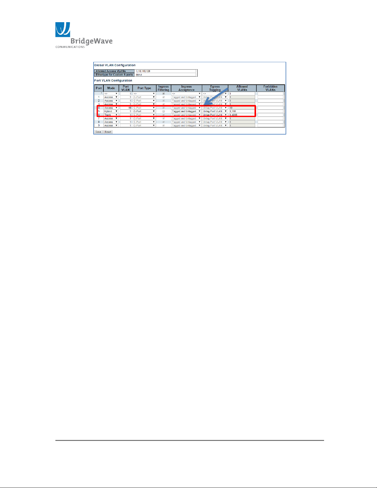
Figure 279: VLAN Port Access
This configuration example demonstrate the configuration of Port 4 as access
only to VLAN 10, Port 5 is configured ad Hybrid allowing only C tag frames
(x8100) with VLAN 1 and 110, Port 6 is configured as Trunk to allowed a
range from 1 – 4095 VLANs which include VLAN ID 120.
3. Test the new VLAN IDs access to the radios management
interface.
- Connect a PC to each port with the specify IP address
range and test connectivity to the IP address of the
management interface configured.
A PC (NO VLAN tag) using the same IP address
range of VLAN 10 (10.100.7.x) is connected to port
4 and pings are successfully sent to the
management IP address 10.100.7.247(low band) of
the radio.
A PC (VLAN tag 110) using the same IP address
range of VLAN 110 is connected to port 5 and pings
are successfully sent to the management IP address
110.10.10.1 of the radio. This port also allows VLAN
ID 1 and/or untagged frames.
A PC (VLAN tag 120) using the same IP address
range of VLAN 120 is connected to port 6 and pings
are successfully sent to the management IP of
172.10.10.1 of the radio. This port allows a range
of VLANs: 1 – 4095, per configuration.
This configuration will not allow inter access between the different IP address
range used. Also, to access the unit from outside the subnet, IP Routes will
need to be configured for each IP address range.
Page 45
Page 45 of 84
040-57105-01
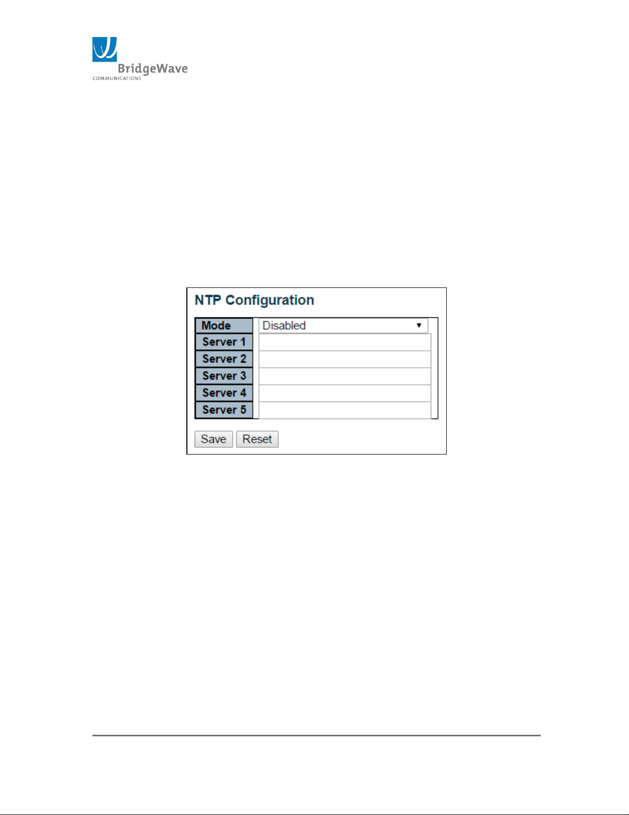
NTP: Network Time Protocol, use for synchronizing the system clock
with an NTP Server.
Mode: Enable/Disable (Default: Disable)
Server 1 – 5: Each one of these 5 fields permits the entry of
either and IPv4 address or an IPv6 address of the NTP server.
Save Button: Save setting before moving to another page. If
the save button is not apply, the new configuration on this page
will be lost.
Reset Button: If configuration has been applied but has not
been saved, clicking this button will reset the page back to
previous settings.
Figure 28: NTP Configuration Page
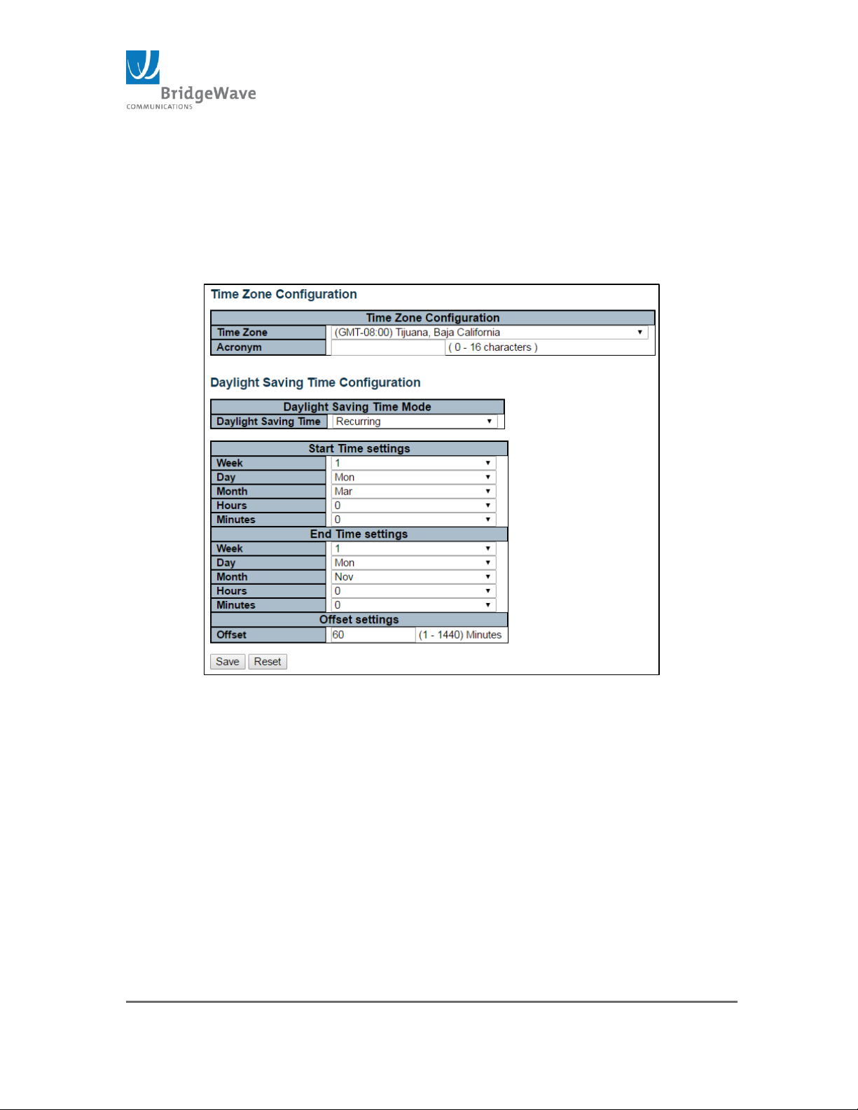
Time: This page allows for the configuration of the Time Zone.
Time Zone – List various Time Zones worldwide. Select Time
Zone from the drop down and click Save to set.
Acronym - User can set the acronym of the time zone. Range up
to 16 characters.
Daylight Saving Time – This is used to set the clock forward or
backward according to the configurations set under the “Start”,
“End” and “Offset” Settings table. Options to select from: Disable
(default), Recurring, & Non-recurring
Start Time and End Time Settings – These included the
Month, Date, Year, Hours, & Minutes.
Offset – Enter the number of minutes to add during Daylight
Saving Time (Range: 1 – 1440)
Page 46
Page 46 of 84
040-57105-01
Save Button: Save setting before moving to another page. If
the save button is not apply, the new configuration on this page
will be lost.
Reset Button: If configuration has been applied but has not
been saved, clicking this button will revert the page back to
previous settings.
Figure 29: Time Zone Configuration Page
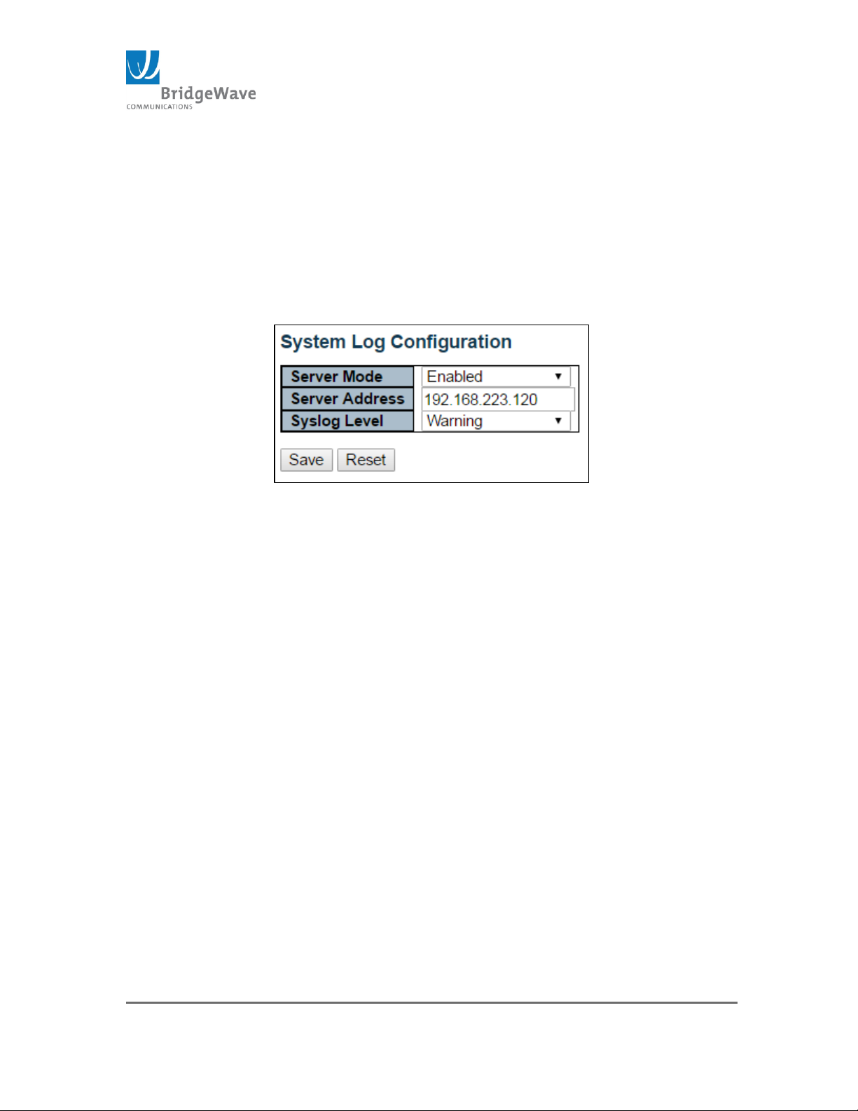
Log: System Log Configuration page.
Server Mode: Enable / Disable (Default mode) When the mode
of operation is enabled, the syslog will send messages to the
syslog server configured under the “Server Address” field. The
syslog protocol is based on UDP communication and received on
UDP port 514. Due to the nature of UDP, no acknowledgments
will be sent back during the communication between host and
server.
Server Address: Used an IPv4 host address of the syslog
server. If the switch provide DNS feature, it can also be a host
name.
Page 47
Page 47 of 84
040-57105-01
Syslog Level: Indicates that type of message level that will be
sent to the syslog server. Options are: Info, Warning, & Error.
Save Button: This buttons must be click to save the new
settings before moving to another page.
Reset Button: If configuration has been apply but has not been
save, clicking this button will revert the page back to previous
settings.
Figure 30: System Log Configuration Page
Page 48
Page 48 of 84
040-57105-01
Ports
Selecting from the navigation pane Switch>Configuration>Ports will open the
following screen:
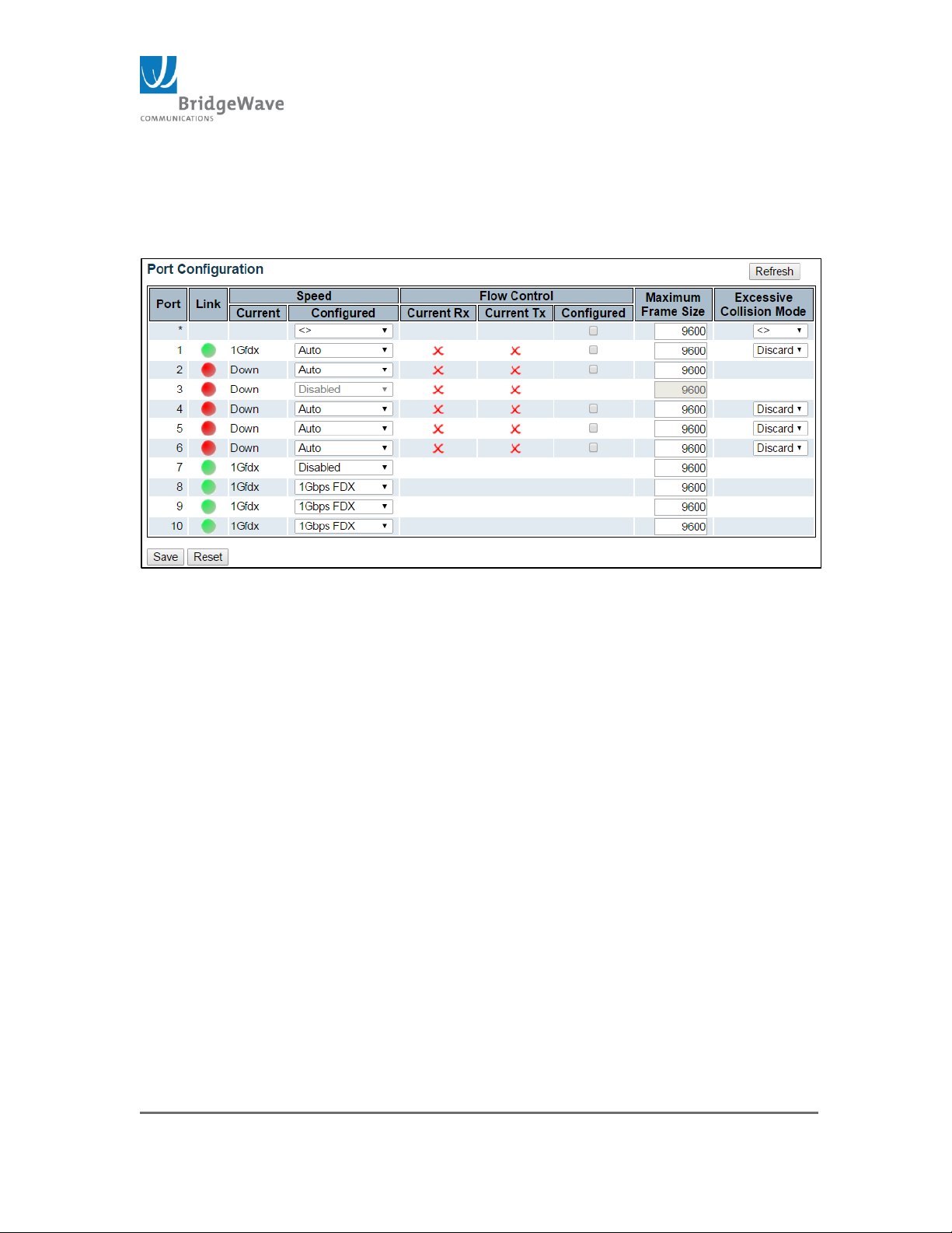
Figure 33: Port Configuration Page
This page allow port configuration as well as it displays current port settings.
Port: This is the logical port number for this row.
Link: The current port state is graphically displayed on this row. Green
indicates the link is up. While red, indicates the link is down.
Speed, Current : Provides the current link speed of the port
Speed, Configured: Selects any available link speed for the given
switch port. Only speeds supported by the specific port are shown.
Possible speeds are:
o Disabled – Turns port off
o Auto – Port auto negotiating speed with the link partner and
selects the highest speed that is compatible with the link partner.
o 10Mbps HDX – Forces the copper port to 10Mbps half-duplex
mode.
o 10Mbps FDX - Forces the copper port to 10Mbps full-duplex
mode.
o 100Mbps HDX - Forces the copper port to 100Mbps half-duplex
mode.
o 100Mbps FDX - Forces the copper port to 100Mbps full-duplex
mode.
Page 49

Page 49 of 84
040-57105-01
o 1Gbps FDX – Forces the port to 1000Mbps full duplex
o SFP_Auto_AMS - Automatically determines the speed of the
SFP. NOTE: There is no standardized way to do SFP auto detect,
therefore, the SFP rom read to determine the speed.
The port is set in AMS mode. Cu port is set to Auto mode.
100 –FX – SFP port in 100-FX speed. Cu port disabled.
100 –FX_AMS – Port in AMS mode. SFP port in 100-FX speed. Cu
port in Auto mode
1000-X – SFP port in 1000-X speed. Cu port disabled.
1000-X_AMS – Port in AMS mode. SFP port in 1000-X speed. Cu port
in Auto mode.
Ports in AMS mode with 1000-X speed has Cu port
preferred
Ports in AMS mode with 1000-X speed has fiber port
preferred
Ports in AMS mode with 100-FX speed has fiber port
preferred
Flow Control: When Auto Speed is selected on a port, this section
indicates the flow control capability that is advertised to the link
partner. When a fixed-speed setting is selected, that is what is used.
The Current Rx column indicates whether pause frames on the port are
obeyed and the Current Tx column indicates whether pause frames on
the port are transmitted. The Rx and Tx settings are determined by the
results of the last Auto-Negotiation.
NOTE: Check the configured column to use flow control. This setting is
related to the setting for Configured Link Speed.
Maximum Frame Size: Enter the maximum frame size allowed for the
switch port, including FCS. The range for this field is 1518 – 9600
bytes.
Excessive Collision Mode: Configure port Transmit collision behavior.
Available options:
Discard: Discard frame after 16 collisions (default)
Restart: Restart back off algorithm after 16 collisions
Save Button: This buttons must be click to save the new settings
before moving to another page.
Page 50
Page 50 of 84
040-57105-01
Reset Button: If configuration has been applied but has not been
saved, clicking this button will reset the page back to previous settings.
Refresh Button: This button refreshes the page. Any changes not
save will be undone and if the partner port has changed its state, the
refreshed page will reflect it.
Users
Selecting from the navigation pane
Switch>Configuration>Security>Switch>Users will open the following screen:
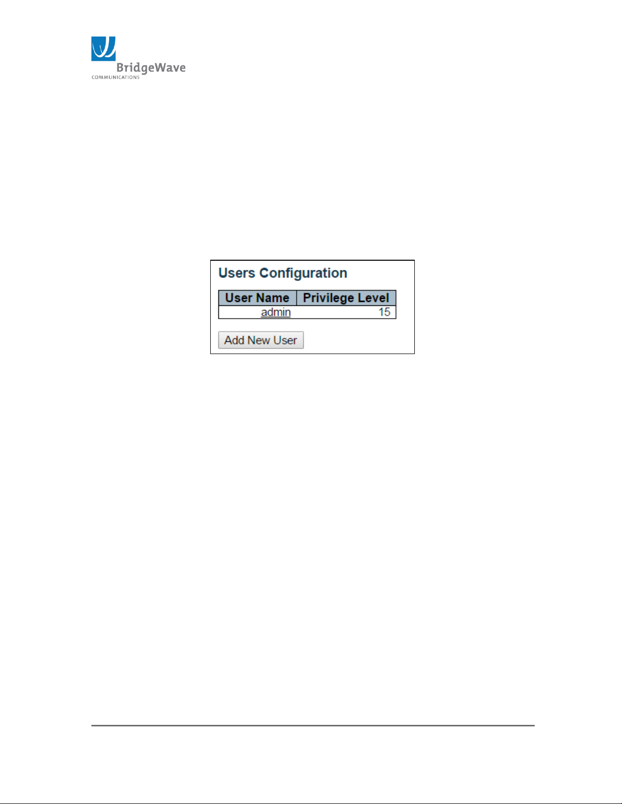
Figure 31: User and Access Level
This page provides an overview of the current users. Currently the only way
to login as another user on the web server is to close and reopen the browser
User Name: The name identifying the user. NOTE: The default
configuration comes with “admin” and no password configured.
Privilege Level: The privilege level of the user. The allowed range is 1
to 15. If the privilege level is 15, the user is granted full control of the
device. User’s privilege should be same or greater than the group
privilege level to have access to that group. By default, most groups’
privilege level is configured to 5, which grants read-only access.
Privilege level 10 grants read-write access. To any system
maintenance (software upload, factory defaults and etc.), level 15 must
be assigned or granted to the group. Generally, Privilege level 15 is
granted to administrator account, privilege level 10 is granted to
standard user account and privilege level 5 is use for a guest account.
Add New User Button: Click to add a new user. Clicking this button
opens a new page that allows for new user information to be input:
Page 51
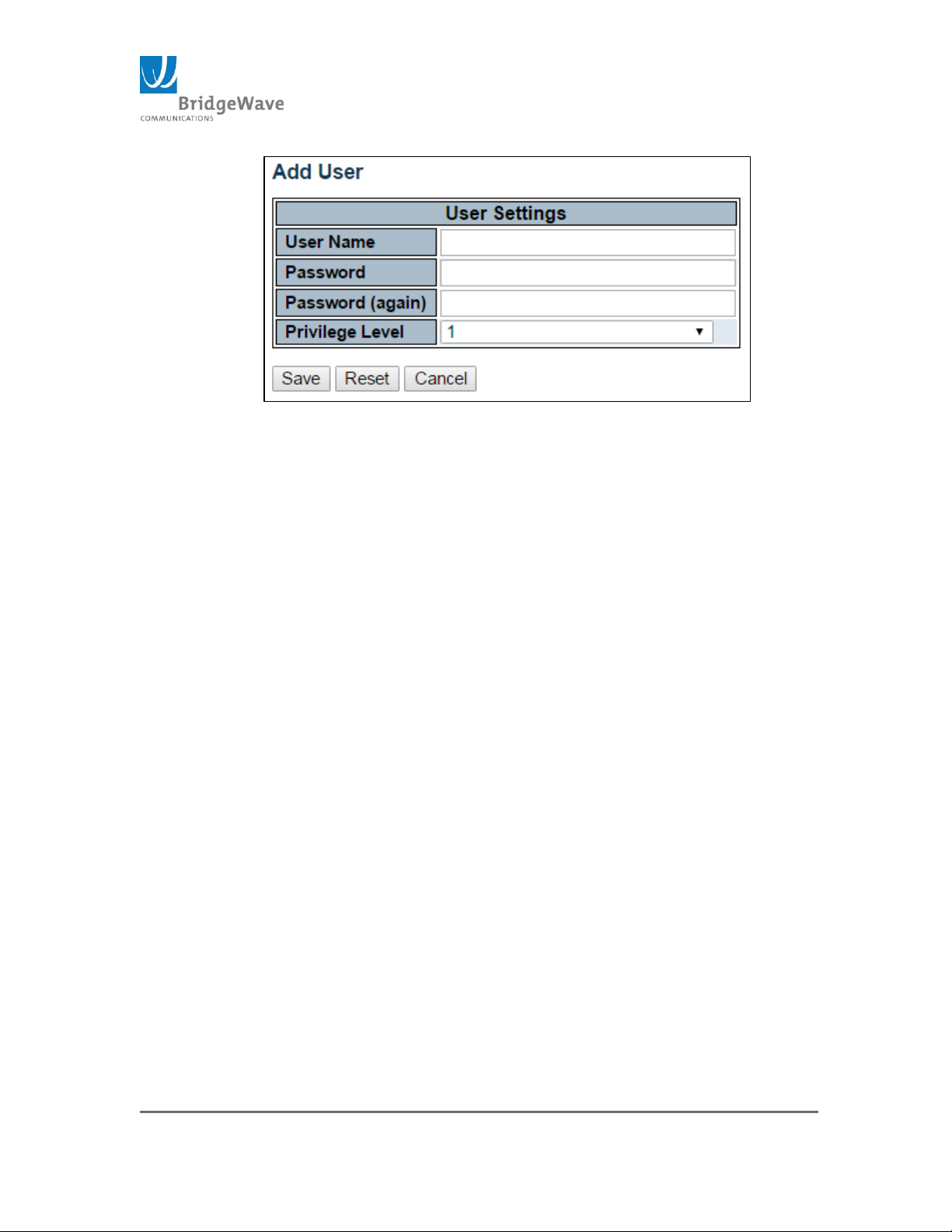
Page 51 of 84
040-57105-01
Figure 32: Add User/Password Setting
User Name: A string identifying the new user name. The allowed string
length is 1 to 31. The valid user name allows letters, numbers and
underscores.
Password: The password of the user. The allowed string length is 0 to
31. Any printable characters including space is accepted
Privilege Level: The privilege level of the user. The allowed range is 1
to 15.
Note: Privilege level setting is not available for Radio
settings only Switch control settings.
Save Button: This button must be click to save the new settings
before moving to another page.
Reset Button: If configuration has been applied but has not been
saved, clicking this button will reset the page back to previous settings.
Cancel Button: This button will undo any changes made, if not save,
and return to the User Configuration page.
Delete Button: This button deletes the current user account. This
button is only available for existing user.
Page 52
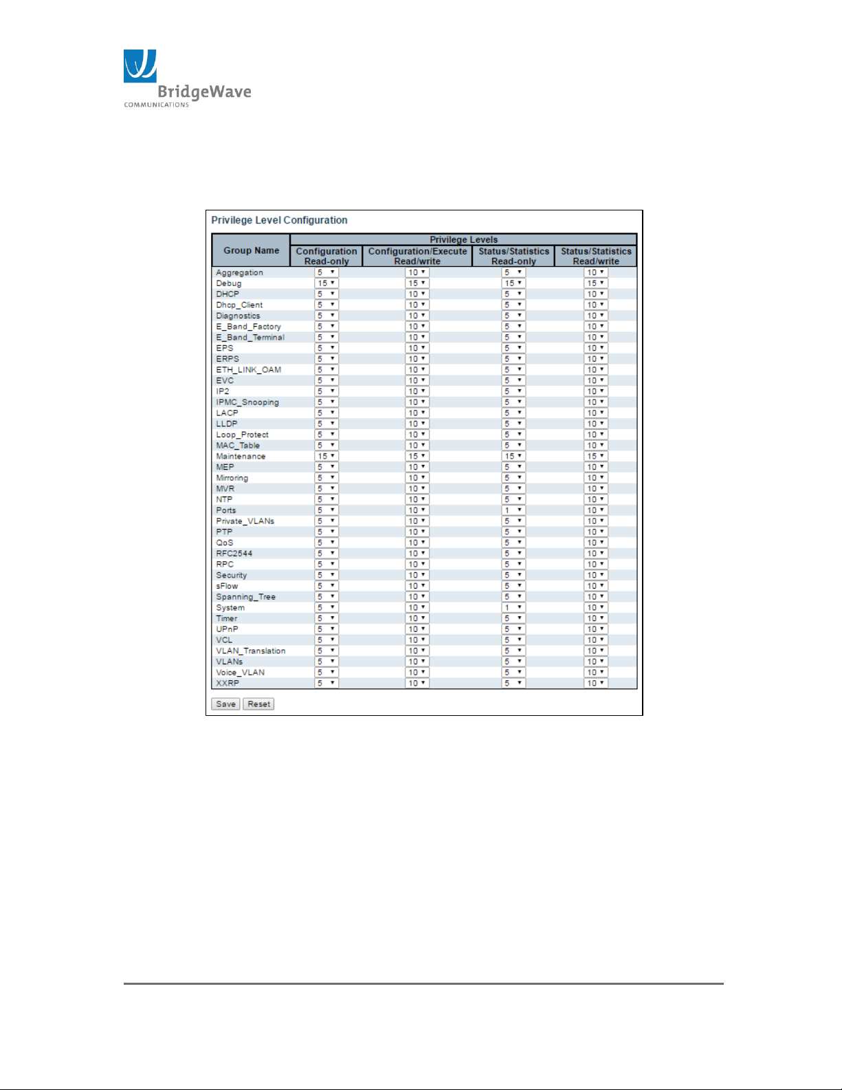
Page 52 of 84
040-57105-01
Privilege Levels
Selecting from the navigation pane Switch>Configuration>
Security>Switch>Privilege Levels will open the following screen:
Figure 33: Privilege Level Configuration Page
This page provides an overview of the privilege levels configured by default.
In most cases, a privilege level group consists of a single module (e.g. LACP,
RSTP or QoS), however a few of them have access to more than one.
The following defines the Group Names and Privilege Levels
Group Name:
System: Contact, Name, Location, TimeZone, Daylight
Savings Time, Log, Security, Authentication, System Access
Page 53
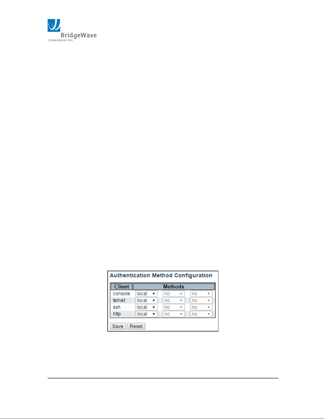
Page 53 of 84
040-57105-01
Management, Port(Dot1x port, MAC based and MAC Address
Limit), ACL, HTTPS, SSH, ARP, IP source guard.
IP: Everything except ’ping’.
Port: Everything except ‘VeriPHY’
Diagnostics: ‘ping’ and ‘VeriPHY’
Maintenance: CLI- System Reboot, System Restore Default,
System Password, Configuration Save, Configuration Load
and Firmware Load. Web-Users, Privilege Levels and
everything in Maintenance.
Debug: Only present in CLI
Privilege Levels: Every group has an authorization Privilege level for the
following sub groups:
Configuration Read-only
Configuration/execute read-write
Status/statistics read-only
Status/statistics read-write (e.g. for clearing of statistics)
Save Button: This button must be click to save the new settings
before moving to another page.
Reset Button: If configuration has been applied but has not been
saved, clicking this button will reset the page back to previous settings.
Authentication Method
Selecting from the navigation pane Switch>Configuration>
Security>Switch>Auth Method will open the following screen:
Figure 34: Authentication Method Configuration Page
This page allows you to configure how a user is authenticated when logged
into the switch via one of the management client interfaces.
Page 54

Page 54 of 84
040-57105-01
The table has one row for each client type and a number of columns describe
as follows:
Client: There are four management client access options:
Console
Telnet
SSH
HTTP
Methods: The management clients are given access via the following
methods:
NO: Authentication is disabled and login is not possible
Local: Use the local user database on the switch for
authentication
RADIUS: Use remote RADIUS server(s) for authentication
TACACS+: Use remote TACACS+ server(s) for authentication
Note: Methods that involves remote servers are timed out if the remote
servers are offline. In this case the next method is tried. Each method
is tried from left to right and continues until a method either approves
or rejects a user. If a remote server is used for primary authentication,
it is recommended to configure secondary authentication as “local”.
This will enable the management client to login via the local user
database if none of the configured authentication servers are available
or offline.
Save Button: This button must be click to save the new settings
before moving to another page.
Reset Button: If configuration has been applied but has not been
saved, clicking this button will reset the page back to previous settings.
SSH
Selecting from the navigation pane,
Switch>Configuration> Security>Switch>SSH will open the following screen:
Figure 35: SSH Configuration Settings
Page 55
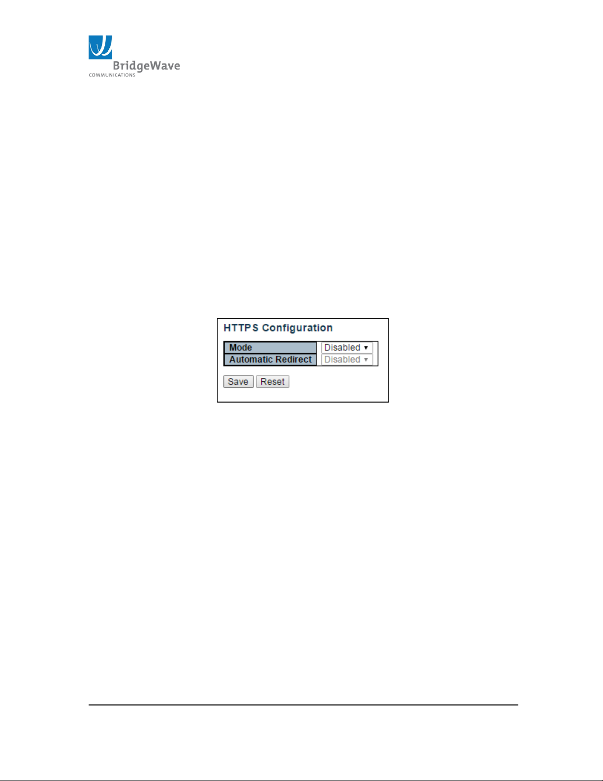
Page 55 of 84
040-57105-01
Secure Shell allows the data to be exchanged using a secure channel between
the radio and the accessing device. The encryption used by SSH provides
confidentiality and integrity of data over an insecure network.
The Configuration page allows for the following settings:
Mode: Enable / Disable (Default)
Save Button: This button must be click to save the new settings
before moving to another page.
Reset Button: If configuration has been applied but has not been
saved, clicking this button will reset the page back to previous settings.
HTTPS
Selecting from the navigation pane Switch>Configuration>
Security>Switch>HTTPS will open the following screen:
Figure 36: Authentication Method Configuration Page
Hypertext Transfer Protocol over Secure Socket Layer (HTTPS) provides
authentication and encrypted communication for sensitive communication.
HTTPS uses port 443. SSL uses a 40-bit key size for the RC4 stream
encryption algorithm.
The Configuration page allows for the following settings:
Mode: Enable / Disable (Default setting)
When Disabled, the unit will automatically redirect browser to port
80/HTTP connection
Automatic Redirect: Enable / Disable (Default setting)
Mode has to be Enabled before Automatic Redirect can work. Redirects
Web Browser to an HTTPS connection.
Save Button: This button must be click to save the new settings
before moving to another page.
Reset Button: If configuration has been applied but has not been
saved, clicking this button will reset the page back to previous settings.
Access Management
Page 56
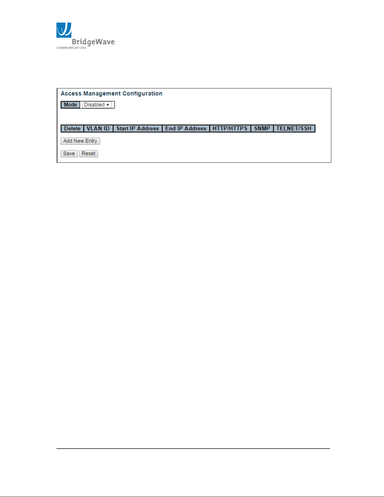
Page 56 of 84
040-57105-01
Selecting from the navigation pane Switch>Configuration>
Security>Switch>Access Management will open the following screen:
Figure 37: Access Management Configuration Page
The configuration management table has a maximum of 16 entries. If the
application’s type matches any one of the access management entries, it will
allow access to the radio.
The configuration page allows the following setting:
Mode: Enable / Disable (Default setting)
Delete: Check this box to delete and existing Access Management
Configuration. It will be deleted during the next save
VLAN ID: Indicates the VLAN ID for the access management entry
Start IP address: Indicates the start IP address for the access
management entry
End IP address: Indicates the end IP address for the access
management entry
HTTP/HTTPS : Indicates that the host can access the unit from
HTTP/HTTPS interface if the host IP address matches the IP address
range provided in the entry
SNMP: Indicates that the host can access the switch from SNMP
interface if the host IP address matches the IP address range provided
in the entry
TELNET/SSH: Indicates that the host can access the switch from
TELNET/SSH interface if the host IP address matches the IP address
range provided in the entry
Add New Entry: Click to add a new access management entry.
Clicking this button open a new entry. The following figure illustrates
the “Add New Entry” button action:
Page 57
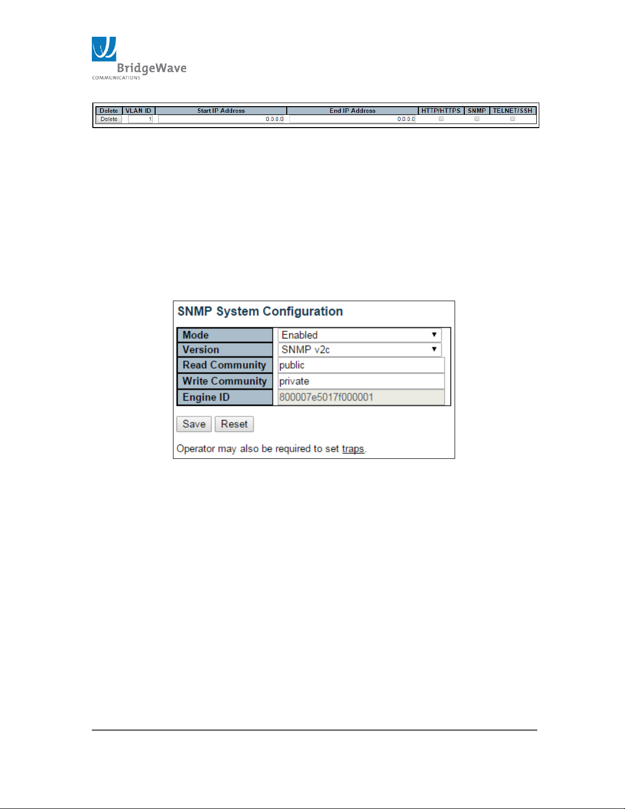
Page 57 of 84
040-57105-01
Figure 38: Add New Entry to Access Management Configuration
Save Button: This button must be click to save the new settings
before moving to another page.
Reset Button: If configuration has been applied but has not been
saved, clicking this button will reset the page back to previous settings.
SNMP
Selecting from the navigation pane Switch>Configuration>
Security>Switch>SNMP>System will open the following screen:
Figure 39: SNMP System Configuration
SNMP
Simple Network Management Protocol is part of the Transmission Control
Protocol/Internet Protocol. SNMP Agent allows the radio to participate in a
network management architecture.
Mode: Enable/Disable
Version: SNMPv1/SNMPv2c/SNMPv3
Read Community: Indicates read string to permit access to SNMP
agent. The allowed string length is 0 to 255 characters, and the
allowed content is the ASCII characters from 33 to 126.
NOTE: The field is applicable only when SNMP version v1 and v2c. SNMPv3’s
community string will be associated with the communities table. If provides more
flexibility to configure security name than version v1 and v2c community string. In
Page 58
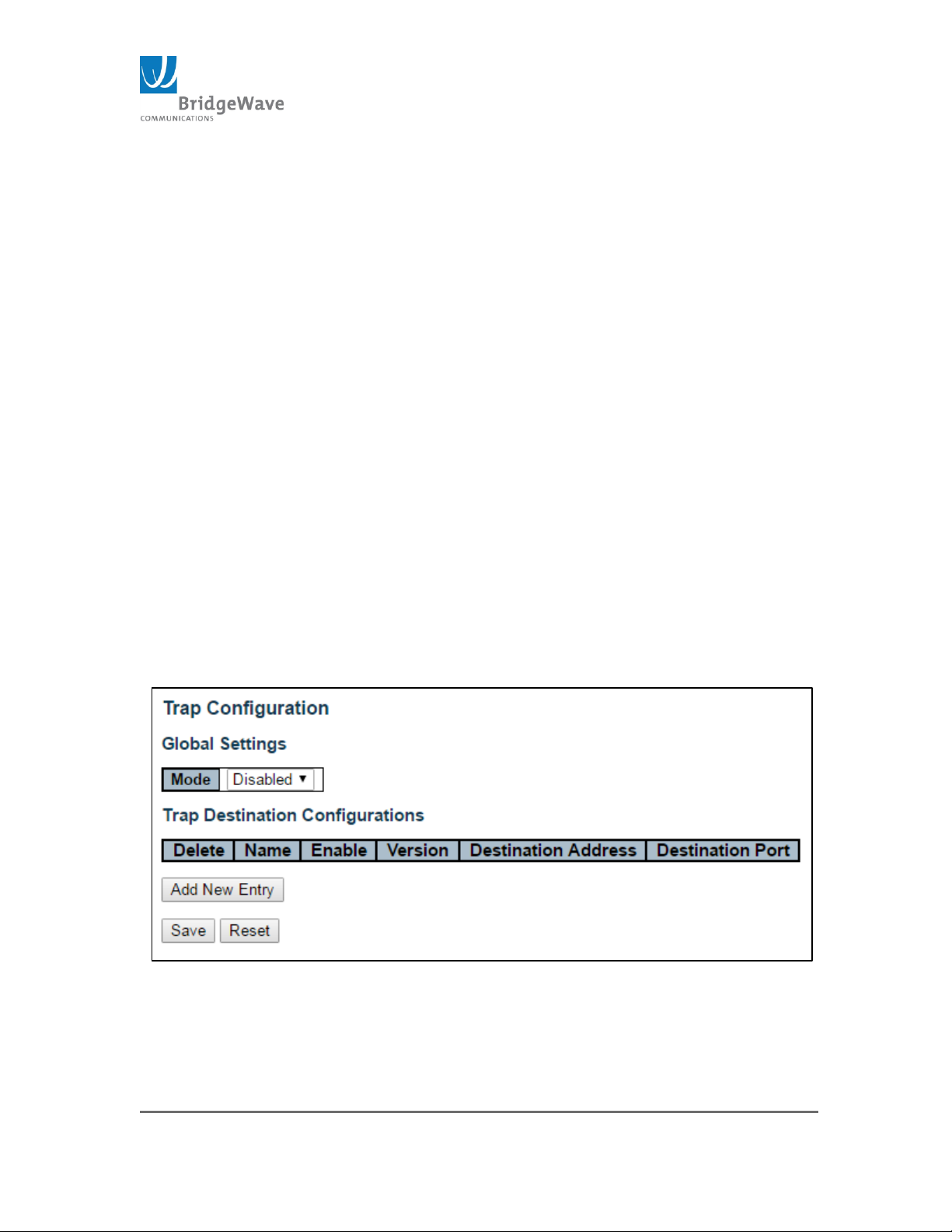
Page 58 of 84
040-57105-01
addition to community string, a particular range of source addresses can be used to
restrict source subnet.
Wire Community: Indicates write string to permit access to SNMP
agent. The allowed string length is 0 to 255 characters, and the
allowed content is the ASCII characters from 33 to 126.
NOTE: The field is applicable only when SNMP version v1 and v2c.
SNMPv3’s community string will be associated with the communities
table. If provides more flexibility to configure security name than version
v1 and v2c community string. In addition to community string, a
particular range of source addresses can be used to restrict source
subnet.
Engine ID: Indicates the SNMPv3 engine ID. The string must contain
an even number (in hexadecimal format) with number of digits
between 10 and 64, but all-zeros and all-F’s are not allowed. Change
of the Engine ID will clear all original local users.
Traps, Configuration Submenu
Selecting from the navigation pane Switch>Configuration>
Security>Switch>SNMP>Trap will open the following screen:
Figure 40: Trap Configuration Settings
SNMP Traps are update messages sent to the defined trap server to report on
abnormal changes on the operation of the radio.
Page 59
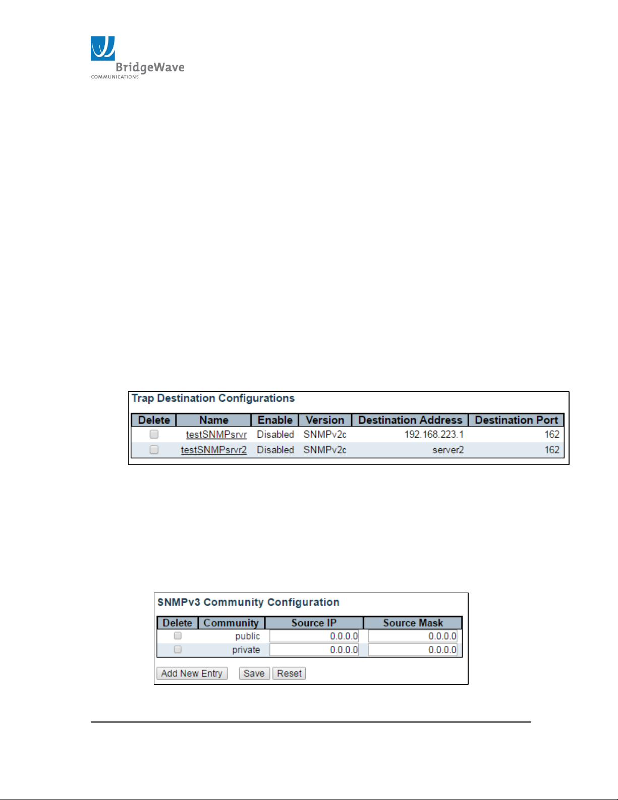
Page 59 of 84
040-57105-01
This page allows for the configuration of SNMP traps.
Mode: Enable/Disabled
Delete: Selecting this checkbox will delete the Trap Destination entry
once the “Save” button is click
Name: Indicates the trap Destination Configuration’s name
Enable: Indicates if that specific entry is either on or off
Destination Address: Indicates the SNMP trap destination address. It
displays an IP address in dotted decimal notation (1.1.1.1). It also
allows a valid hostname.
NOTE: A valid hostname is a string drawn from the alphabet (A-Za-z),
digits (0-9), dot (.), dash (-). Spaces are not allowed, the first
character must be in alpha character, and the first and last characters
must not be a dot or a dash.
Destination Port: Indicates the SNMP trap destination port. The SNMP
agent will send SNMP messages via this port. The valid port range is 1
– 65535.
Figure 41: Example of Setting Trap Destination
Community, Configuration Submenu
Selecting from the navigation pane Switch>Configuration>
Security>Switch>SNMP>Community will open the following screen:
Figure 42: SNMPv3 Community Configuration Page
Page 60
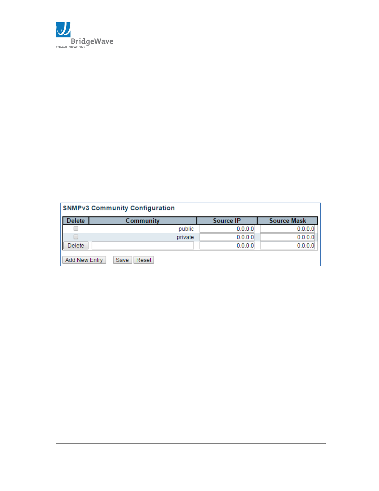
Page 60 of 84
040-57105-01
This page allows for the configuration of the SNMP v3 Community IP source
address for added security.
Delete: check to delete the entry. It will be deleted during the next
save.
Community: Indicates the community access string to permit access
to SNMPv3 agent. The allowed string length is 1 to 32, and the allowed
content is ASCII characters from 33 to 126. The community string will
be treated as security name and map a SNMPv1 or SNMPv2c
community string.
Source IP: Indicates the SNMP access source address. A particular
range of source addresses can be used to restrict source subnet when
combined with source mask.
Source Mask: Indicates the SNMP access source address mask.
Add New Entry Button: Adds a new community entry. When click, a
new entry is display. See image below:
Figure 43: SNMPv2 Community Configuration, New Entry
Save Button: This button must be click to save the new settings
before moving to another page.
Reset Button: If configuration has been applied but has not been
saved, clicking this button will reset the page back to previous settings.
Aggregation Static, Configuration Submenu
Selecting from the navigation pane
Switch>Configuration>Aggregation>Static will open the following screen:
Page 61
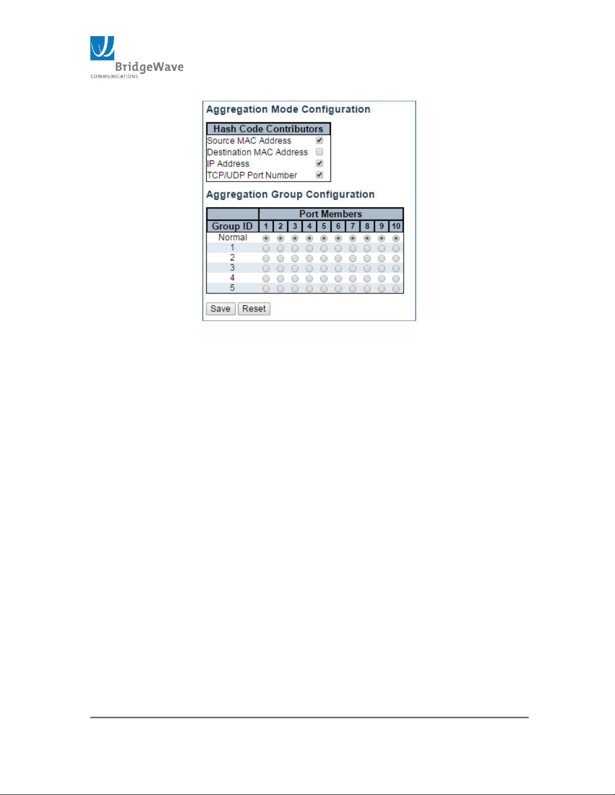
Page 61 of 84
040-57105-01
Figure 44: Static Aggregation Configuration
Aggregation groups use multiple ports in parallel to increase the link speed
beyond the limits of a port and to increase the redundancy for higher
availability. The radio uses aggregation group number 5 to provide more than
1Gbps over the air speed. Licensing a link to 2Gbps or 3Gbps, requires the
configuration of the wireless ports (7, 8, 9, & 10) to be members of group 5
aggregation.
This page allows the configuration of the Static Aggregation groups. The
system uses a Hash Code Algorithm to calculate per frame distribution
between the group’s member ports. The system allows for the selection of
specific frame’s header information to run the Hash algorithm. The following
options are part of the frame’s header and are used to generate the Hash
Code:
Source MAC Address
Destination MAC Address
IP Address
TCP/UDP Port Number
NOTE: The more options selected the better the distribution.
Aggregation Group Configuration:
Group ID: Indicates the group ID for the settings contained in
the same row. Group ID “Normal” indicates there is no
aggregation. Only one group ID is valid per port.
Page 62

Page 62 of 84
040-57105-01
Port Members: Each switch port is listed for each group ID.
Select a radio button to include a port in an aggregation, or clear
the radio button to remove the port from the aggregation. By
default, no ports belong to any aggregation group. Only full
duplex ports can join an aggregation and ports must be in the
same speed in each group.
Save Button: This button must be click to save the new settings
before moving to another page.
Reset Button: If configuration has been applied but has not
been saved, clicking this button will reset the page back to
previous settings.
Page 63
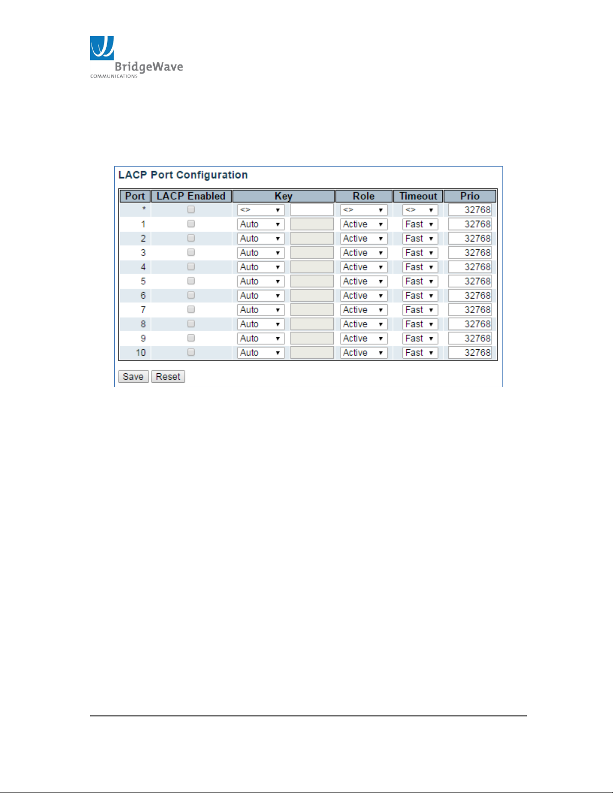
Page 63 of 84
040-57105-01
LACP
Selecting from the navigation pane Switch>Configuration>Aggregation>LACP
will open the following screen:
Figure 45: LACP Port Configuration
Link Aggregation Control Protocol, LACP, is an IEEE 802.3ad standard protocol
that allows bundling several physical ports together to form a single logical
port. The radio does allow for multiple aggregation groups.
This page allows the configuration of the LACP protocol using the following
parameters:
Port Column: The switch port number
LACP Enabled: Controls whether LACP is enabled on the switch port.
LACP will form an aggregation when 2 or more ports are connected to
the same partner.
Key: The key value incurred by the port, range 1-65535.
o Auto: The auto setting will set the key as appropriate by the
physical link speed, 10Mb = 1, 100Mb = 2, 1Gb = 3.
o Specific: A user defined value can be entered. Ports with the
same Key value can participate in the same aggregation group,
while ports with different keys cannot.
Role: The role shows the LACP activity status.
o Active: The Active role will transmit LACP packets each second
o Passive: The Passive will wait for a LACP packet from a partner.
Page 64
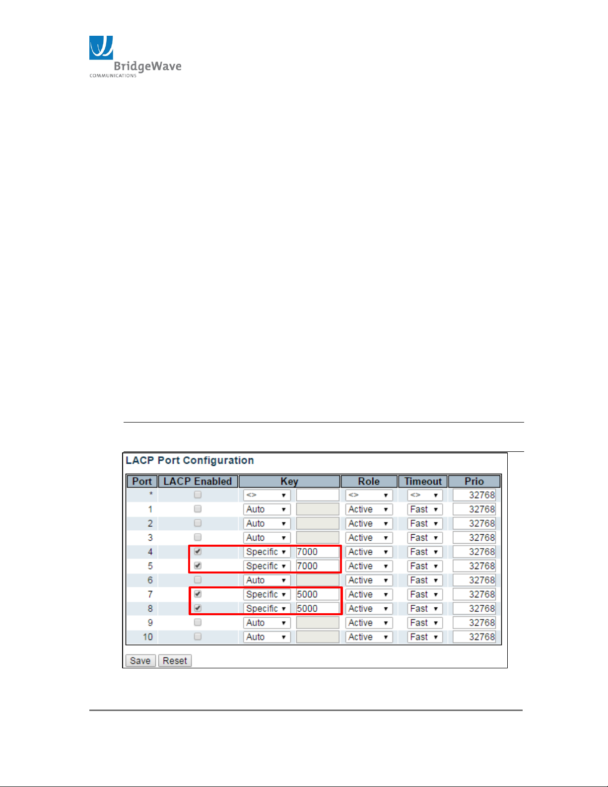
Page 64 of 84
040-57105-01
Timeout: The Timeout controls the period between BPDU
transmissions.
o Fast: The Fast will transmit LACP packets each second.
o Slow: The Slow will wait for 30 seconds before sending a LACP
packet.
Prio: The Prio(ity) controls the priority of the port. If the LACP partner
to form a larger group than is supported by this device then this
parameter will control which ports will be active and which ports will be
in a backup role. Lower number means greater priority.
Save Button: This button must be click to save the new settings
before moving to another page.
Reset Button: If configuration has been applied but has not been
saved, clicking this button will reset the page back to previous
settings.
Example of LACP Configuration:
Creates a 2Gbps bond
Ports 4 and 5 are bonded via LACP group using specific key 7000
Ports 7 & 8 are bonded via a separate LACP group using specific
key 5000
NOTE: When using LACP, the member ports cannot also be members
of a Static Aggregation group.
Figure 46: Example of LACP Configuration
Page 65
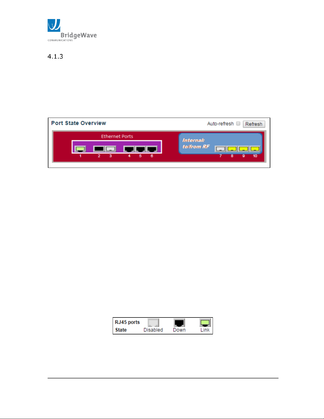
Page 65 of 84
040-57105-01
Monitor
This section will review the most important pages of the Monitor tool use to
troubleshooting problems with the radio.
Ports
Selecting from the navigation pane Switch>Monitor>Ports will open the
following screen:
Figure 47: Port State Overview
The Port State Overview identifies which ports are active, down, or not
connected. The radio has 10 ports, 6 LAN ports and 4 Wireless ports.
LAN Ports: Ports 1 – 6
1. Ports 1, 4 – 6 are 10/100/1000Mbps ports
2. Ports 2 & 3 are SFP cages.
These ports can be used with Fiber (MM or SM), Cupper, and/or
CPRI SFP modules.
Wireless Ports: 7 – 10
1. Each port is 1000Mbps/1Gbps ports capable
2. Each port receives a fraction of the total available wireless
bandwidth. Examples:
1. 2Gbps wireless link, Port 7, 8, 9 & 10 are on
Each port gets 500Mbps. 2000Mbps /4 ports.
2. 3Gbps wireless link, Port 7 & 8 are on
Each port only gets 1000Mbps. That is because each
port is 1000Mbps port only.
Port States: The port states are illustrated as follows:
Figure 52: Port State status
Auto-refresh: The Auto-refresh checkbox, when selected, it will
automatically refresh the state every 3 second.
Page 66
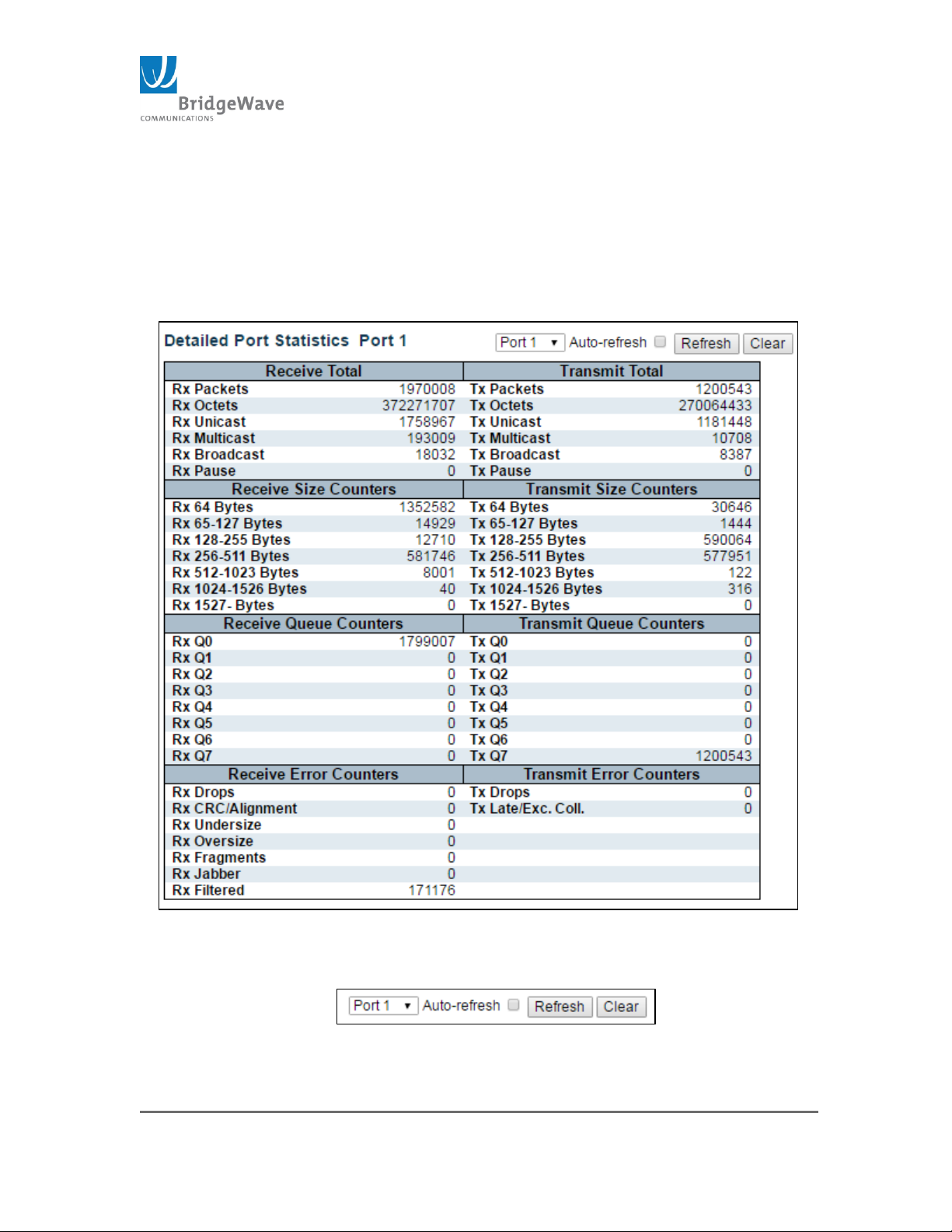
Page 66 of 84
040-57105-01
Refresh Button: Click to manually refresh the page.
NOTE: Hover the mouse cursor over the top of each port and the current
state will display.
Click on a port: Clicking on a port will open the Detailed Port Statistics
page for that port. Figure for example counters:
Figure 48: Example of Detailed Port Statistics
Utility Buttons:
Figure 49: Utility Buttons
Page 67
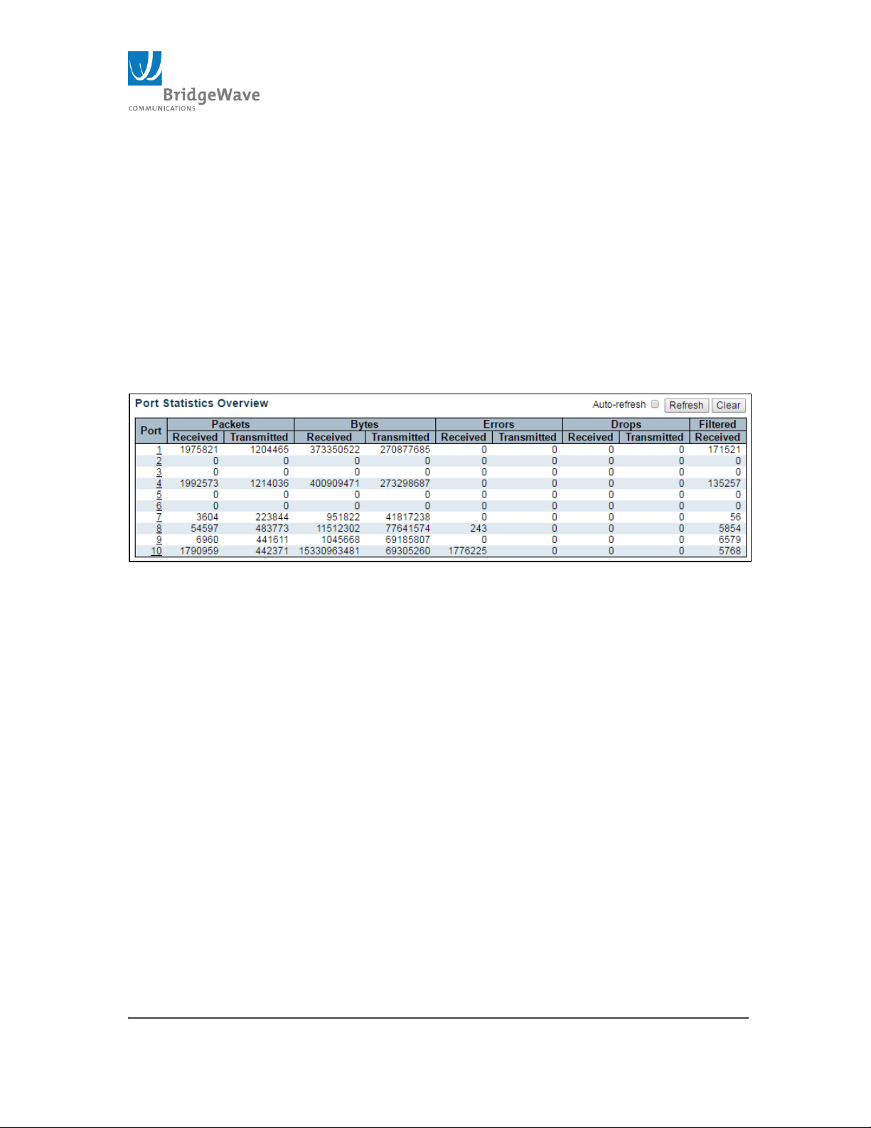
Page 67 of 84
040-57105-01
Port Selection: This pull down menu allows the selection of any of the
other 10 ports.
Auto-refresh check box: Selecting this box, will refresh the page every
3 seconds.
Refresh button: Refresh the page manually/immediately
Clear button: Clears all counters for the selected port.
Traffic Overview
Selecting from the navigation pane Switch>Monitor>Traffic Overview will
open the following screen:
Figure 50: Example Port Statistics Overview
This page provides a quick analysis of all the ports. The page is divided into 6
columns and is describe as follow:
Port: The logical port for the settings contained in the same row.
Packets: The number of received and transmitted packets per port
Bytes: The number of received and transmitted bytes per port
Errors: The number of frames received in error and the number of
incomplete transmission per port
Drops: The number of frames discarded due to ingress or egress
congestion
Filtered: The number of received frames filtered by the forwarding
process.
Auto-refresh check box: Selecting this box, will refresh the page
every 3 seconds.
Refresh button: Refresh the page manually/immediately
Clear button: Clears all counters for the selected port. (Refer to
previous section for an image of this page.)
Page 68

Page 68 of 84
040-57105-01
NOTE: Hover on top of each port and clicking on it, will display the
Detailed Port Statistics Port page.
Most of the counters are self-explanatory, however the Error Counters section
are as follow:
Rx Drops: The number of frames dropped due to lack of receive
butters or egress congestion
Rx CRC/Alignment: The number of frames received with Cyclic
Redundancy Check or alignment errors
Rx Undersize: The number of short frames received with valid
CRC.
NOTE: short frames are frames that are smaller than 64 bytes.
Rx Oversize: The number of long frames received with valid CRC.
NOTE: Long frames are frames that are longer than the configured
maximum frame length for this port.
Rx Fragments: The number of short frames received with invalid
CRC.
Rx Jabber: The number of long frames received with invalid CRC
Rx Filtered: The number of received frames filtered by the
forwarding process.
Tx Drops: The number of frames dropped due to output buffer
congestion.
Tx Late/Exc. Coll.: The number of frames dropped due to
excessive or late collisions.
Port Selection: This pull down menu allows the selection of any
of the other 10 ports.
Auto-refresh check box: Selecting this box, will refresh the page
every 3 seconds.
Refresh button: Refresh the page manually/immediately
Clear button: Clears all counters for the selected port.
Maintenance
This section allows the physical manipulation of the device/unit/radio. Restart,
Factory Defaults, Software and Configuration upload and download are all
perform under this section.
Restart Device
Page 69
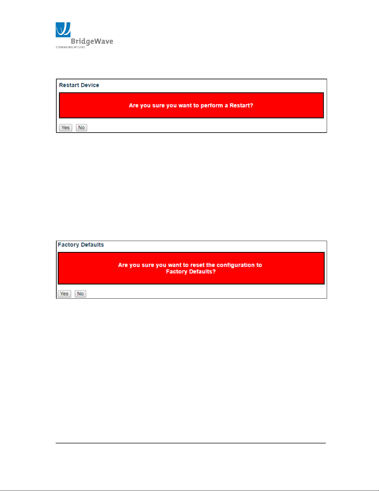
Page 69 of 84
040-57105-01
Selecting from the navigation pane Switch>Maintenance>Restart Device open
the following screen:
Figure 51: Restart Device (ODU)
Restart the device. The system will take about 90 seconds be completely
operational. However, access to the unit can be performed after 30 seconds.
Two Buttons on to control this page:
Yes Button: Click to restart device.
No Button: Click to return to the Port Stat page without
restarting
Factory Defaults
Selecting from the navigation pane Switch>Maintenance>Restart Device
opens the following screen:
Figure 52: Factory Defaults
This page allows for reverting of the configuration on the unit to factory
settings. Only the IP address configuration is retained. The default
configuration is available immediately, which means that no restart is
necessary.
Yes Button: Click to reset the configuration to Factory Defaults.
No Button: Click to return to the Port State page without
resetting the configuration.
NOTE: Restoring the factory default can also be performed by making
physical loopback between port 1 and port 2 within the first minute from
switch reboot. In the first minute after boot, “loopback” packets will be
transmitted at port 1. If a “loopback” packet is received at port 2, the switch
will do a restore to default.
Page 70
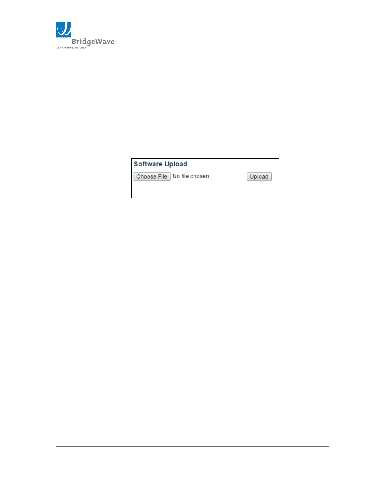
Page 70 of 84
040-57105-01
Software
This subsection has two pages, Upload and Image Select. These two options
allow the manipulation of the unit’s running code, either reverting back to a
different code that resides within the memory location cations, or loading new
code.
Upload:
Selecting from the navigation pane
Switch>Maintenance>Software>Upload opens the following screen:
Figure 53: Software Upload
This page is use to upload new GUI/UI software to the unit’s Active Image
memory location. This code only controls the switch and the interfacing with
the unit.
NOTE: Radio/FPGA code is loaded via the CLI interface.
Choose File Button: Use this button to locate the new software
to be uploaded into the system
Upload Button: Click to upload the file once the file has been
selected.
NOTE: After the software image is uploaded, a page announces that the
firmware update is initiated. After about a minute, the firmware is updated
and the switch restarts.
Warning: While the firmware is being updated, Web access appears to be
defunct. The front LED flashes Green/Off with a frequency of 10Hz while the
firmware update is in progress. Do not restart or power off the device at
this time or the switch may fail to function afterwards.
Image Select:
Page 71
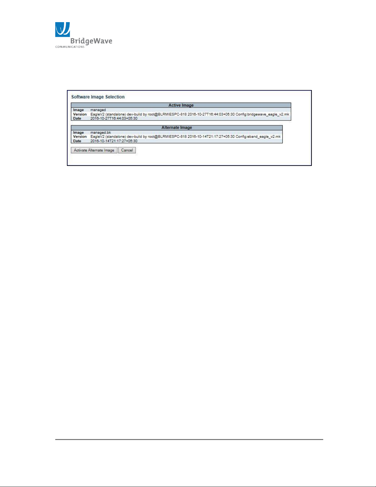
Page 71 of 84
040-57105-01
Selecting from the navigation pane
Switch>Maintenance>Software>Image Select opens the following
screen:
Figure 54: GUI Software Images
This page provides information about the active and alternate (backup)
firmware images in the device, and allows you to revert to the alternate
image.
Two tables are display within this pane. These tables are described as follow:
Active Image: This is the current, running software in the device.
Alternate Image: This is the backup image that resides on the
secondary memory location and it is use to revert the device to this
version if the current image fails.
The table provides the following information regarding the images:
Image: The flash index name of the firmware image. The name
of primary (preferred) image is “managed”, the alternate image
is name “managed.bk”
Version: The version of the firmware image. A condensed image
name/version is also available under the Factory page of the
Radio Functions menu.
Date: The date when the firmware was produced.
Activate Alternate Image Button: Click to use the alternate image.
NOTE: This button may be disabled depending on system state.
Cancel: Cancel activating the backup image. Navigates away from this
page to the Port State Overview.
Configuration
Page 72
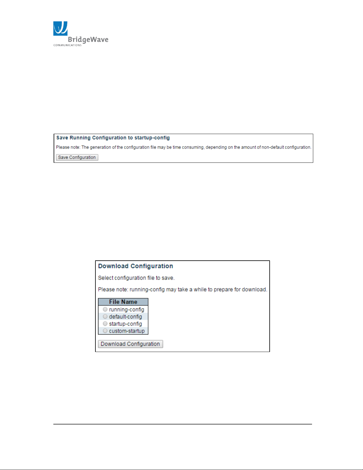
Page 72 of 84
040-57105-01
This subsection control system configuration by either: Saving the
configuration, Download the configuration, Upload a different configuration,
Activate an existing configuration and Delete an existing configuration.
Save Startup-
Selecting from the navigation pane
Switch>Maintenance>Software>Image Select opens the following
screen:
Figure 55: Save Running Configuration
After configuring the unit to meet the network requirements, all configuration
changes will need to be store in nonvolatile memory location. If this is not
performed, all changes will be lost once the unit reboots.
This page contains one “Save Configuration” button. Clicking on this button
will save the configuration into the “Running Configuration” memory location
and a message of a successful save will display.
Download Configuration
Selecting from the navigation pane
Switch>Maintenance>Software>Download opens the following screen:
Figure 56: Download Configuration Page
It is possible to download any of the files on the unit’s memory location
to a host computer. Select the radio button next to the file name and
click on the “Download Configuration” button.
Page 73
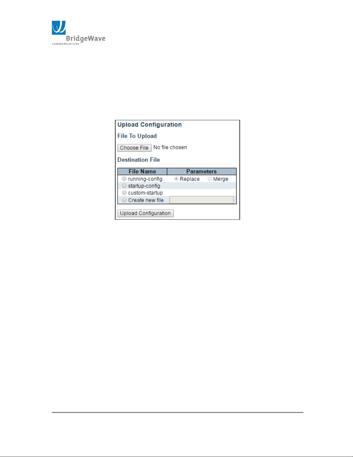
Page 73 of 84
040-57105-01
NOTE: The running-config may take a little longer to complete, as the
file must be prepared for download.
Upload Configuration
Selecting from the navigation pane
Switch>Maintenance>Software>Upload opens the following screen:
Figure 57: Upload Configuration
This page is use to upload a file from the web browser to all the files on
the switch, except default-config, which is read-only. If the destination
is running-config, the file will be applied to the switch configuration.
This is done in two ways:
Replace Mode: The current configuration is fully replaced with
the configuration file uploaded
Merge mode: The uploaded file is merged into running-config
NOTE: If the file system is full (i.e. contains all three system files
plus two other files), it is not possible to create new files. One of the
existing files must be overwritten or deleted first.
Choose File Button: Use this button to locate the new
configuration file to be uploaded into the system
Upload Configuration button: Use this button to upload the new
file, but only after a file location has been selected (i.e. select the
File Name’s radio button from the list)
Activate
Page 74
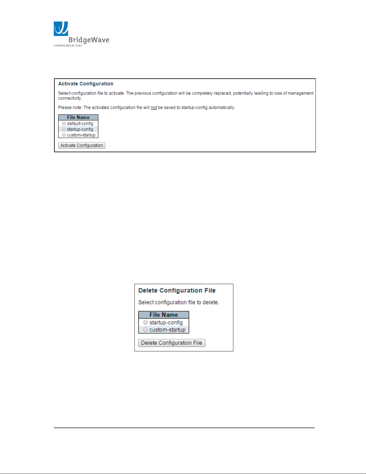
Page 74 of 84
040-57105-01
Selecting from the navigation pane
Switch>Maintenance>Software>Activate opens the following screen:
Figure 58: Activate Configuration(s)
This page allows switching between three configuration files. The active
configuration will not be saved to startup-config automatically. The three file
options are:
Default-config
Startup-config
Custom-config
Select the file to active and click the “Activate Configuration” button. This will
initiate the process of completely replacing the existing configuration with that
of the selected file.
Delete
Selecting from the navigation pane
Switch>Maintenance>Software>Delete opens the following screen:
Figure 59: Delete Configuration File
This page allows the deletion of any files stored in flash, including startup-
config.
NOTE: It this is done and the switch is rebooted without a prior Save
operation, this will reset the switch to default configuration.
Page 75

Page 75 of 84
040-57105-01
Select the file to delete and click the “Delete Configuration File”.
Page 76

Page 76 of 84
040-57105-01
5 UI & MODEM Update Procedures via CLI
Tools and Methods
Tools and equipment needed for software update
PC or laptop with telnet or SSH enabled
Ethernet cable to connect to the radio
UI Software Update Package
The factory default IP addresses for the FLEX4G-LITE V² are:
Low Band: 10.100.7.247
High Band: 10.100.7.248
If the IP address of the target radio was previously changed, use
that address along with user ID and password where required.
Update Using Command Line Interface
This method requires a Telnet connection from the host PC to the radio. In
addition, a TFTP server is required to host the new UI package.
Follow this step to perform the update:
1. Copy the FLEX4G-LITE UI upgrade file to a known location on the
host PC. The upgrade file extension ends with “.gz”
2. Start a TFTP server (NBTFTP.exe) on the host PC.
3. Set the search directory of the TFTP server to the directory where
the upgrade software is located.
4. Open a Command window on the host PC.
5. Telnet to the target FLEX4G-LITE radio by typing at the system
prompt:
6. C:\>telnet <ip_addr>
7. Connection should establish and the radio will respond with a
request for the Username. Enter “admin”. A request for
password will follow. The default password is <enter> or return
on the PC keyboard.
8. The FLEX4G-LITE will send a message with the number of error
entries in the syslog and then display a prompt.
Page 77
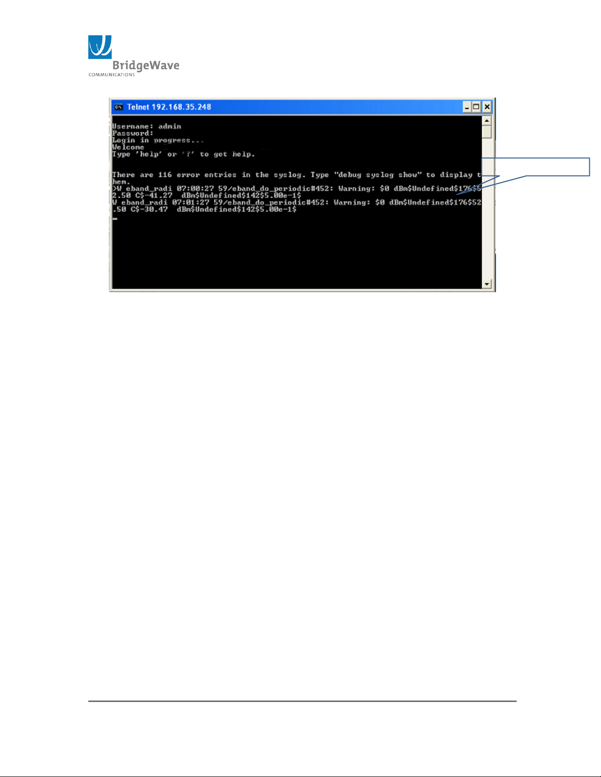
Page 77 of 84
040-57105-01
Periodic Status
Figure 60: CLI Periodic Status Message
In addition, the FLEX4G-LITE sends a periodic status message when
connected. This message is sent every minute. A sample message is shown
above. This message display can be disabled using the following CLI
commands. Disabling the periodic message reduces the possibility of
mistyping.
>debug trace module level eband_radi default none
>debug trace module level eband_fpga default none
9. The syntax for uploading the UI image uses the follow CLI
command.
>debug firmware managed.bk <ip_addr of TFTP server> <file name:
LITExxx.gz>
For example:
>debug firmware load managed.bk 10.100.7.3 LITE0004.gz
The command tells the radio software to load into the backup image memory
location the UI image available from the TFTP server located at 10.100.7.3
with the file name of FLEX4G-LITE0004.exe.
10. The radio will return the following message when the command
is executed:
Download ‘‘ <filename>’’ , x,xxx,xxx bytes
Erasing image...
Programming image...
Page 78

Page 78 of 84
040-57105-01
Value
Description
0
no command
Programmed xxxxxxx bytes (checksum 0xxxxxx) to managed.bk -- OK
The time for this process is 3-5 minutes to complete.
11. After the software image upload is completed. Use a web
browser and log into the target radio using the IP address of the
radio in the URL bar. Navigate to Maintenance>Software>Image
select and click on Activate Alternate Image select. This
command actives the alternate image and places the active image
in standby.
Update FPGA/Modem Firmware
Upgrading FPGA/CPU modem firmware uses requires the following:
PC with Telnet services
TFTP server on a PC that the FLEX4G-LITE radio has access
FPGA/CPU modem firmware package
1. Start the TFTP server on a PC that the FLEX4G-LITE radio has
access.
2. Copy new FPGA/CPU modem code to the TFTP server directory.
3. Start up a telnet session to the target FLEX4G-LITE radio.
>telnet [ip_addr]
4. Enter user name, (admin), and password, (enter or return), at
the prompts
5. Enter Determine which of the three available memory locations
will be used to store the new code. Use the following command
sequence to determine which memory location is operational:
>upgrade cpu page
NOTE: The FLEX4G-LITE radio will return one of the following string
messages for example:
>Upgrade cmd [x] succeeded with status 0x0
The value after the word status defines the operational firmware
Factory 0x0 = memory factory default
APP 1 0x4 = memory slot 1
APP 2 0x8 = memory slot 2
APP 3 0xc = memory slot 3
Page 79
Page 79 of 84
040-57105-01
1
load app from DDR to flash
2
reconfigure FPGA
3
status = startup reason
4
load app from flash to DDR
5
status = 1 if running app, 0 if factory
6
status = app start page
7
calculate CRCs of flash apps
8
last entry, number of commands
Table 3: CMD Parameters
6. Upload the new modem firmware using the following command
>upgrade tftp xfer [tftp_server ip_addr] [modem
file name] [file size] [file checksum]
If the command sequence is inputted correctly, the TFTP server will upload
the firmware to the radio.
After uploading the following message will be displayed at the system prompt.
TFTP get from [ip_addr] [file name] passed length: [modem file
size] CRC correct [file size in hex]. Sending image..
Commit the upload to flash memory type the following command
sequence
>upgrade cpu burn [x]
Where [x] = flash memory slot, x=1, 2, or 3.
Do not attempt to load into the operational memory slot as determined in
step 5 above. If this slot is selected, upload will not commit to flash memory.
The commit to flash memory will take 1 to 2 minutes. After the commit is
complete the radio will return the following sequence
Upgrade cmd [x] succeeded with status 0x0
cmd [x] is defined in Table 3: CMD Parameters
7. Confirm the new FPGA/CPU modem code is operational by
checking the Radio Modem Status by returning to the top level
prompt by inputting the necessary up command at the prompt
and then typing the CLI command for Status.
Page 80
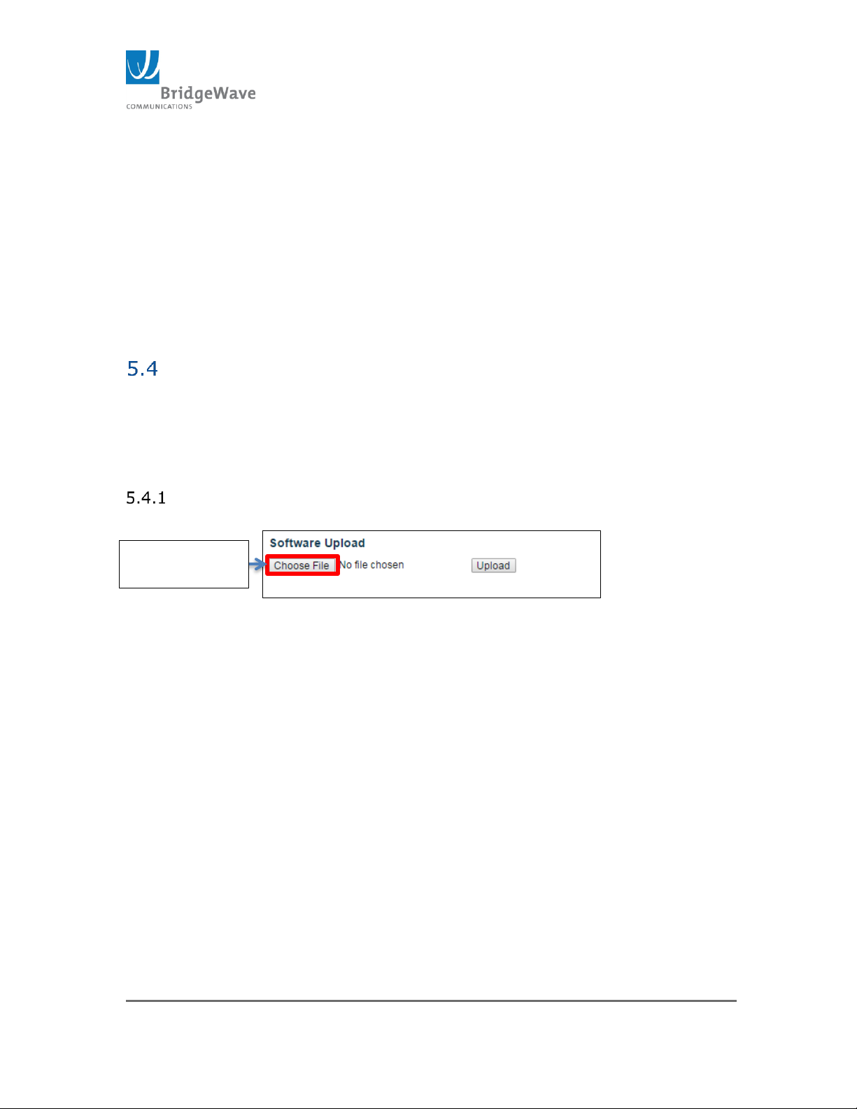
Page 80 of 84
040-57105-01
Click to select
new code
>radio modem status
The radio will return a modem status listing. At the end of the listing look for
the following string.
SELECTED FPGA REV: [xx]
Where value [xx] is the operating FPGA code revision. Refer to Release Notes
accompanying the release for this value.
* If necessary the radio can be rebooted using the following CLI command.
>system reboot
Updating UI using the GUI interface
The User Interface (UI) and FPGA are easily updated using the GUI interface.
Please note that running either update will interrupt the link and/or bring the
link down during the process. It is recommended to have a maintenance
window in place before beginning the process
Updating the UI, click on the Switch>Maintenance>Software>Upload to
access to the software upload page:
Figure 66: Software Upload
1. Click on “Choose File” and navigate to the folder were the
new UI software was previously download it to.
2. Select the .dat file and click “Open”
3. Click on “Upload” to begin the process
4. Once the upload completes, the radio will reload with the
new version.
5. Verification of the new code is done by either checking
the “Controller Version” on the Status Banner, below the
“Serial Number” section
Page 81
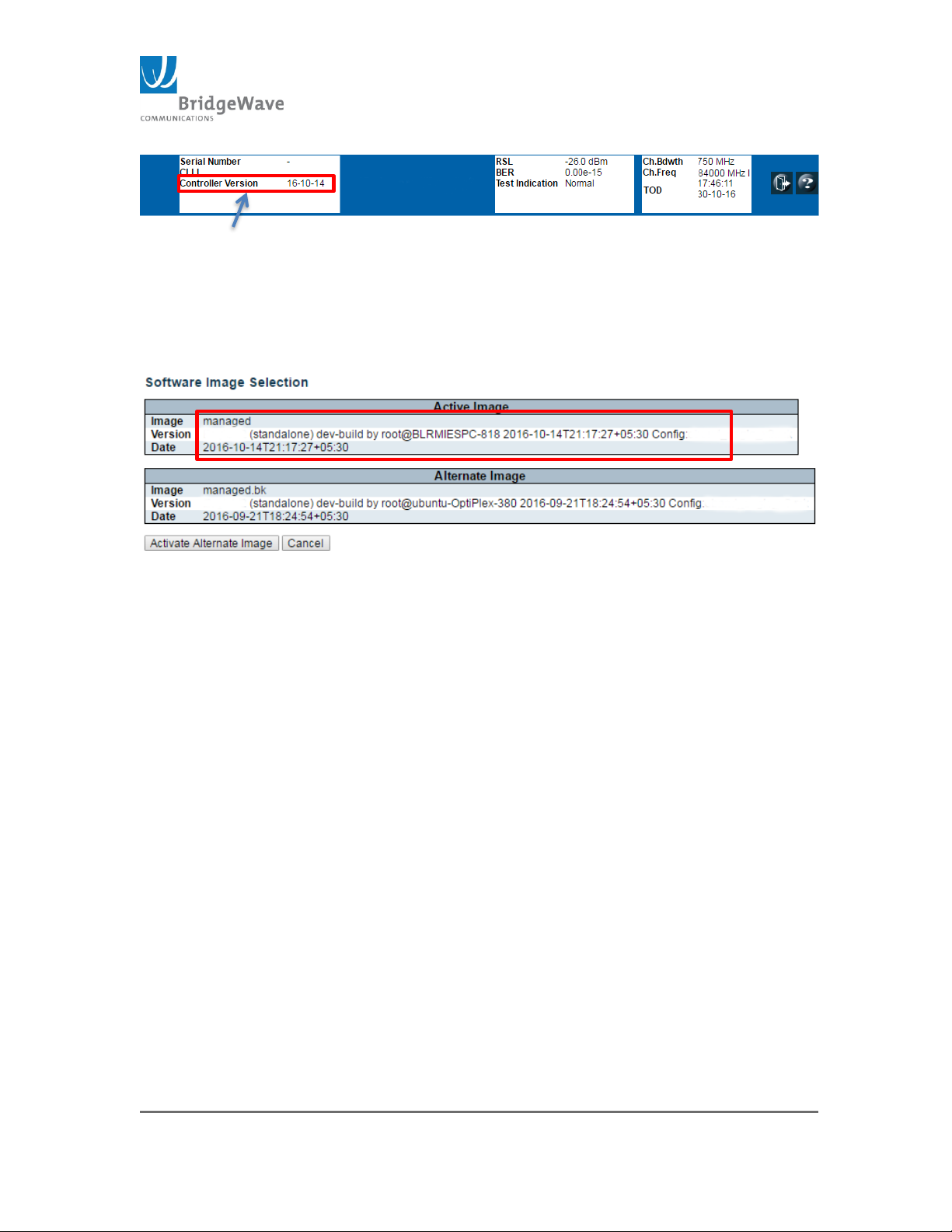
Page 81 of 84
040-57105-01
Figure 67: Controller Version
Or accessing the “Image Select” page, after the upload
the new image will be display under the “Active Image”
section
Click on Switch>Maintenance>Software>Image Select to
access the Software Image Selection:
Figure 68: Software Image Selection
Note: The previous “Active” image will become the “Alternate Image”
Page 82
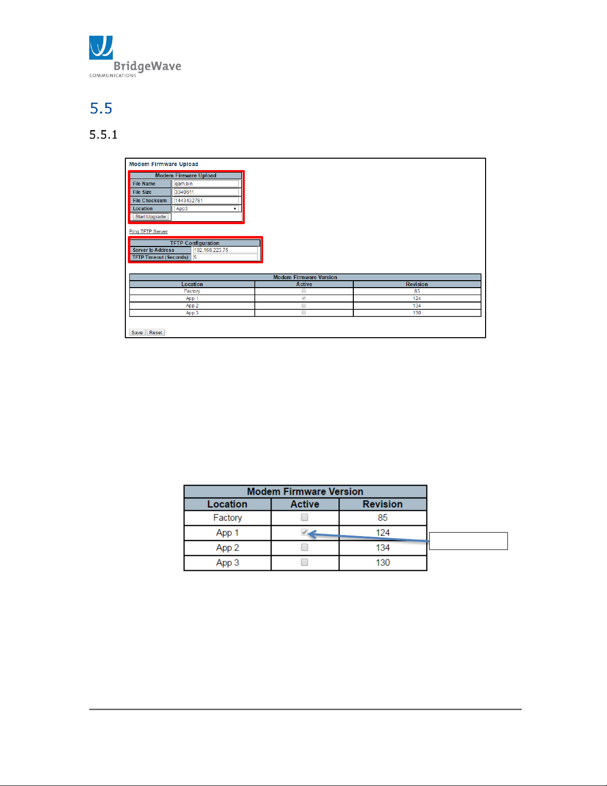
Page 82 of 84
040-57105-01
DO NOT USE
Updating FPGA/Modem Firmware using the GUI interface
Updating the FPGA/Modem Firmware, click on Radio Functions>Modem
Firmware Upload to access the Modem Firmware Upload page:
Figure 69: Modem Firmware Upload
1. Enter the File Name; Example: qam.bin
2. Enter “File Size” and “File Checksum”. These values are
found in the “qam-checksum.txt” file that is included with
the new software code package.
3. Select the “Location”. This will be one of the other two
locations that is not currently Active or selected.
Figure 70: Modem Firmware Version Location
4. Enter the TFTP server IP address.
On this example the TFTP server is running under IP
address 192.168.223.75
Page 83
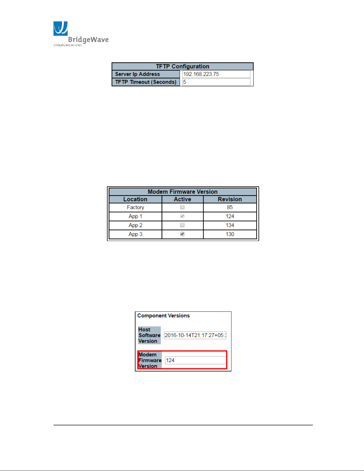
Page 83 of 84
040-57105-01
Figure 71: TFTP Server IP Address
5. Click on “Start Upgrade” to begin the process
NOTE: The link will go down during the upgrade process.
It is recommended that this upgrade is performed on site
(No remote upgrade).
6. Once the process completes, select the location of the
new modem firmware revision. As displayed on Figure
65 above, Location App 3 was selected. Therefore, App 3
will need to be check to active the new code.
Figure 72: Modem Firmware Version Selection
7. Click “Save” to active the new code.
8. Verify the new modem firmware, select Radio
Functions>Factory to access the page. The new version
will be displayed under the “Modem Firmware Version”
field.
Figure 73: Modem Firmware Version
9. If any problems or if the code did not load, try loading
the new version into the other not “Active” App.
Page 84

Page 84 of 84
040-57105-01
Digitally signed by K. Spitz
DN: cn=K. Spitz, o, ou=REMEC Broadband Wireless,
[email protected], c=US
Date: 2016.11.11 10:38:09 -08'00'
If you need any further assistance, contact BridgeWave Support via e-mail at
---End of Manual---
 Loading...