

Page 1
Tire-Pressure Monitoring System
Hand Reader
Operation Guide
For truck and bus
For use only in Europe (model:H212) or
U.S.A. (model:H211)
What is a Tire-Pressure Monitoring System?
Ti re -p re ss ur e mo ni to ri ng s ys te m is a n ad va nc ed s ys te m th at
measures the tire pressure and temperature with sensors mounted
inside the tire and enables vehicle management using the measured
data.
Notice to user
This product is designed exclusively for trucks and buses.
・
This product has two design for use within Europe and USA.
・
It cannot be used other country due to difference in radio wave
regulations. Attention for product model number.
For Europe ...... model H212
For USA .......... model H211
Be sure to read and understand the content of the operation guide
・
before installing or removing.
Keep this guide in a safe place and refer to it as necessary.
・
Page 2
Introduction
Tire-Pressure Monitoring System
For truck and bus
For use only in Europe (model:H212) or
U.S.A. (model:H211)
Hand Reader
Operation Guide
Notice to user
What is a Tire-Pressure Monitoring System?
Tire-pressu re m onit orin g sy stem is an a dvan ced syst em t hat
measures the tire pressure and temperature with senso rs mounted
inside the tire and enables vehicle management using the measured
data.
・
This product is designed exclusively for trucks and buses.
・
This product has two design for use within Europe and USA.
It cannot be used o ther coun try due to differenc e in radio wave
regulations. Attention for product model number.
For Europe......model H212
For USA..........model H211
・
Be sure to read and understand the content of the operation guide
before installing or removing.
・
Keep this guide in a safe place and refer to it as necessary.
This guide describes how to use the hand reader for tire-pressure monitoring system (referred hereafter as "this product"
or "hand reader"). Please read and understand the content before using.
About This Product
This product can collect tire pressure and internal temperature data from the tire-pressure monitoring system sensors
mounted inside the tire (rim) and save them in its memory.
Tire pressure and internal temperature are measured by bringing the antenna of the hand reader near the valve of the
tire and receiving the radio wave. In addition, the following functions are available using the keys.
Store view received data
You can store and view pressure and temperature data for up to 90 vehicles (1080 tires or 90 vehicles x 12 per vehicle
for 12 wheeler).
Refer to section "4-1 Saving and controlling measured data" (page 19) for the content of the saved data.
Transfer saved data to PC
You can use the included Data Transfer Tool to transfer the data saved in the hand reader to a PC in Microsoft Excel
readable format (CSV). You can use the data with many applications once it is transferred.
REG information by tire position
You can register and REG pressure and temperature data by tire position. You can transfer the registered data to PC for
use with other applications.
Package Content
Check that the following items are included in the package.
SAFETY PRECAUTIONS
PART NAMES & FUNCTIONS
BASIC OPERATIONMES modeREG modeVIEWING SAVED DATA
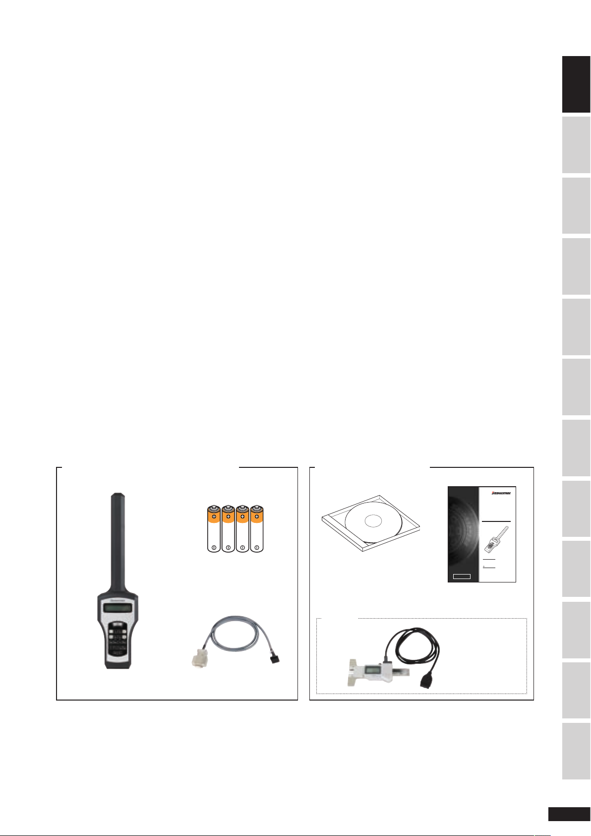
Items included in the hand reader package Optionally purchased items
Battery (AAA) x 4
Data Transfer Tool
CD-ROM x 1
Option
Hand reader x 1 Connection cable x 1
TRANSFERRING SAVED DATA
APPENDIXTROUBLESHOOTINGSERVICE & REPAIRINDEX INTRODUCTION
Operation Guide x 1
Depth gauge
1
Page 3
About Tire-Pressure Monitoring System
Receiver
Sensor
Example of installing
4 receivers and 10 sensors
Receiver
Cable
Vehicle power supply
▪BAT
▪IGN
▪GND
ECU
Display
Warning lamp
Warning lamp
Display
ECU
Receiver
Sensor
Install on dashboard
Install inside cabi
n
Install on vehicle or fram
e
Install inside tire (rim
)
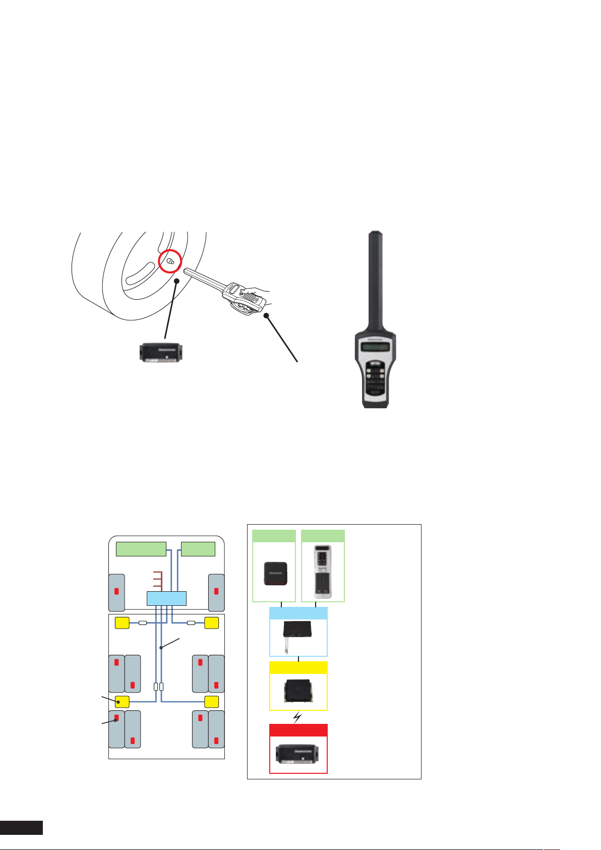
The tire-pressure monitoring system (hereafter referred to as "system" or "this system") is a system that monitors the tire
pressure and temperature using
This system is available as "Hand Reader Type" and "On-Board Type". Purchase the product that is appropriate for your
intended use.
Hand reader type
This system receives the radio wave from the sensor with a portable hand reader.
The radio wave from the sensor is received with the vehicle stopped. It cannot be used when moving.
<Equipment Configuration>
sensors mounted inside tires (rim).
Sensor Hand reader
On-board type
This system measure and monitors the radio wave from the sensor with a display and warning lamp mounted on the
dashboard.
When there is a tire problem, the display and warning lamps on the dashboard emit alarms to notify the driver. The tire
status can be monitored while moving.
<Equipment Configuration>
2
Page 4

Operation Guide Combination
The following two operation guides are necessary to use the Hand Reader type of Tire-Pressure Monitoring System.
Read the guide appropriate for your system.
Guide Content
Tire-Pressure Monitoring System
Hand Reader Operation Guide (this guide)
Tire-Pressure Monitoring System
Sensor Operation Guide
• Unauthorized duplication or reprint of any part of this operation guide or in its entirety is prohibited.
• If this operation manual becomes smudged and unreadable, obtain a new one from your dealer.
• Contact your dealer if there is any misprint or missing page and for questions about its content.
• Microsoft and Excel are registered trademarks of Microsoft Corporation in the U.S. and other countries.
• Other system and product names are registered trademark or trademark of the respective company. The trademark
and copyright symbols are not used in this document.
Describes the hand reader operation method and precautions
Describes sensor installation, rim installation and removal, and
precautions
Warranty and Disclaimer
Warranty
• This is a system that measures the tire pressure and temperature using sensors mounted inside tires (rim).
Bridgestone shall not be liable for any damage resulting from use of this product for other purposes or in combination
with other manufacturer's product.
• Do not disassemble or modify this product. Bridgestone shall not be liable for any damage resulting from disassembly
or modification of this product.
• Read the operation guide carefully and understand its content before using this system. Bridgestone shall not be liable
for any damage resulting from misuse of this product.
• The warranty in case this system fails is limited to the scope described in the warranty notice. Bridgestone makes no
warranty of any kind, implied or otherwise beyond the scope described in the warranty.
SAFETY PRECAUTIONS
PART NAMES & FUNCTIONS
BASIC OPERATIONMES modeREG modeVIEWING SAVED DATA
Product specification limitations
• This system is designed exclusively for trucks and buses.
• This product have two designs for use within Europe and USA. It cannot be used other country due to difference in
radio wave regulations. Attention for product model number.
For Europe : model H212
For USA : model H211
• This system has no function to maintain the status of the tire itself in good condition.
TRANSFERRING SAVED DATA
APPENDIXTROUBLESHOOTINGSERVICE & REPAIRINDEX INTRODUCTION
3
Page 5

Contents
Introduction ................................................................... 1
About This Product ..................................................
Package Content .....................................................
About Tire-Pressure Monitoring System .................
Operation Guide Combination ................................ 3
Warranty and Disclaimer .........................................
Safety Precautions .................................................. 5
1. Part Names and Functions
1-1 Part names and functions ......................... 7
1-2 Replacing batteries ..................................... 8
1-3 Installing/removing the strap (option) ......... 9
2. Basic Operation .................................................... 10
2-1 Power ON ................................................. 10
2-2 Power OFF ............................................... 10
2-3 Turning on the backlight ............................11
2-4 Selecting operation mode .........................11
2-5 Entering numbers ..................................... 12
2-6 Entering characters .................................. 13
2-7 Entering the tire position .......................... 14
2-8 Reading data from sensor ........................ 16
2-9 Viewing the measured data ..................... 16
3. Performing Measurement Only
(MES mode) .......................................................... 17
..................................... 7
8. Troubleshooting .................................................... 37
1
1
2
3
8-1 When battery is low .................................37
8-2 Unable to receive data from sensor ......... 37
8-3 No response when pressing
number keys .............................................
8-4 Nothing appears on the LCD panel .......... 38
8-5 LCD backlight does not turn on ................ 38
8-6 Power does not go OFF ...........................38
8-7 Checking the software version ................. 38
9. Service and Repair ................................................ 39
9-1 Requesting repair ..................................... 39
9-2 Periodic maintenance ............................... 39
9-3 Disposal of the product ............................ 39
9-4 Contact ..................................................... 39
Index .............................................................................
38
40
4. Saving the Measured Data
(REG mode) .......................................................... 19
4-1 Saving and controlling measured data ..... 19
4-2 Vehicle information input/selection flow .. 19
4-3 Entering date, customer number ............. 20
4-4 Entering vehicle number .......................... 21
4-5 Selecting vehicle type .............................. 23
4-6 Entering number of tires .......................... 24
4-7 Selecting axle arrangement ...................... 25
4-8 Selecting measurement target ................ 26
4-9 Specifying tire position ............................. 26
4-10 Reading data from sensor ........................27
4-11
Ending measurement ............................... 28
4-12 Repeating measurement from
the middle ................................................ 29
5. Viewing Saved Data .............................................. 30
6. Transferring Saved Data to PC .............................. 31
6-1 Installing the software .............................. 31
6-2 Transferring Data to PC ............................ 31
6-3 Erasing data saved in hand reader ........... 33
7. Appendix ...............................................................
7-1 Specification ............................................. 34
7-2 Compensated pressure calculation .......... 34
7-3 Measuring groove depth and entering
other REG data .........................................
34
35
4
Page 6
Safety Precautions
Warning symbols
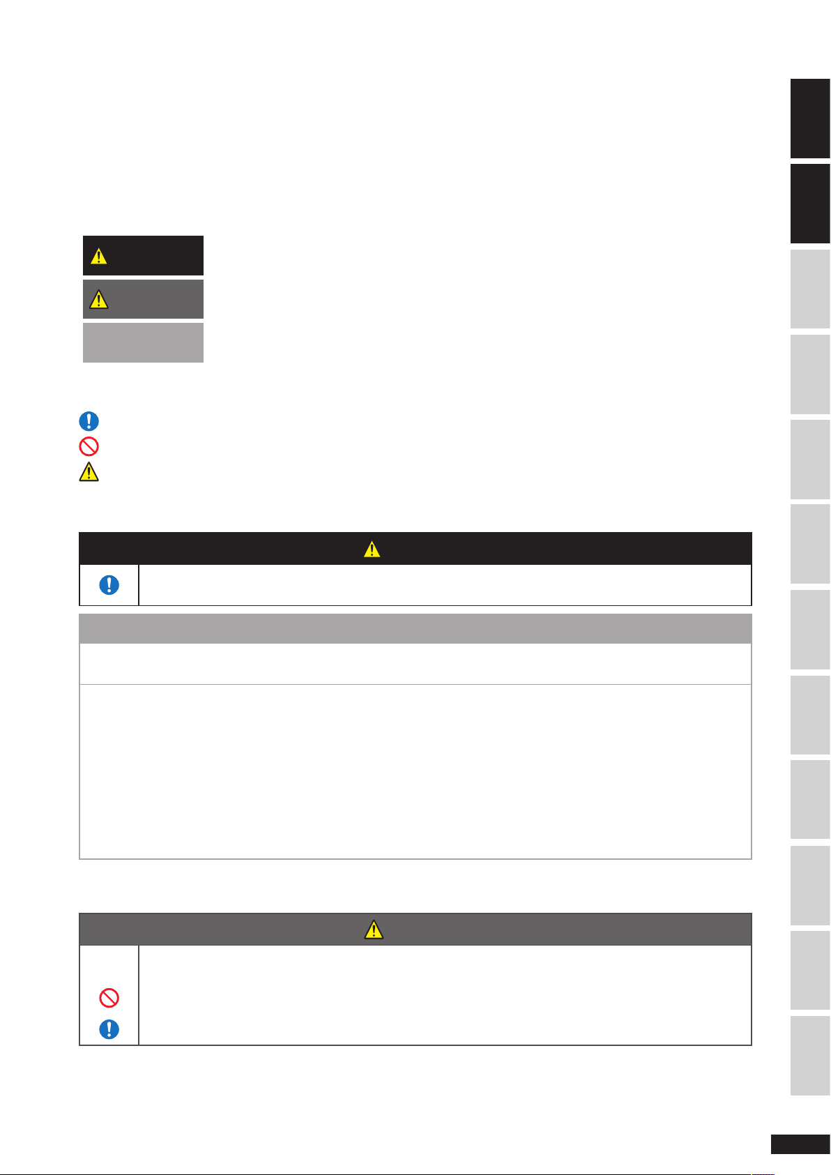
This guide uses the following symbols to describe items that you must observe in order to use the hand reader safely.
Read and observe these items carefully.
WARNING
CAUTION
NOTE
Pictograms
Indicates item that must be observed.
Indicates action that is prohibited.
Indicates danger of bodily harm.
Failure to observe this item may result in death or severe injury.
Failure to observe this item may result in minor injury or property damage.
Failure to observe this item may result in damage to the product.
This also describes items that you should keep in mind.
1. Hand reader handling
WARNING
Stop the vehicle on a level safe location and engage the parking brake before using the hand reader.
Working at an unstable location may cause the vehicle to move and result in accident.
NOTE
• This products are designed for use within Europe or USA. It cannot be used overseas due to difference in radio
wave laws (It’s different radio wave laws Europe and USA).
PART NAMES & FUNCTIONS
BASIC OPERATIONMES modeREG modeVIEWING SAVED DATA
You may damage the hand reader if you fail to observe the following precautions.
• Do not disassemble or modify this product.
• Do not operate with wet hands or where there is moisture.
• Use only specified battery. [AAA dry cell battery (including rechargeable battery)]
• Do not drop, step on, or hit against hard objects.
• Turn off the power before removing the batteries.
• Turn off the power of the hand reader and PC before connecting the hand reader to a PC.
• Do not store in location where there is severe change in temperature or exceeding the allowed temperature range.
• Remove the batteries from the hand reader when it is not used for an extended period.
Otherwise, the batteries may leak and damage the hand reader.
2. Battery handling
CAUTION
Failing to observe the following warnings may cause the battery to leak or heat due to short circuit or
charging and cause it to burst or inflict burns.
• Do not throw batteries in fire, heat it, or disassemble.
• Do not mix new and old batteries or batteries of different manufacturer.
• Make sure the positive and negative poles are correct.
TRANSFERRING SAVED DATA
APPENDIXTROUBLESHOOTINGSERVICE & REPAIRINDEX SAFETY PRECAUTIONS INTRODUCTION
5
Page 7
Notices for using in USA
This device complies with Part 15 of the FCC Rules and IC RSS-Gen. Operation is subject to the following two conditions:
(1) This device may not cause harmful interference, and (2) this device must accept any interference received, including
interference that may cause undesired operation.
This equipment has been tested and found to comply with the limits for a Class B digital device, pursuant to Part 15 of
the FCC Rules and IC RSS-Gen.
These limits are designed to provide reasonable protection against harmful interference in a residential installation. This
equipment generates use and can radiate radio frequency energy and, if not installed and used in accordance with
instructions, may cause harmful interference to radio communications. However, there is no guarantee that interference
will not occur in a particular installation. If this equipment does cause harmful interference to radio or television
reception, which can be determined by turning the equipment off and on, the user is encouraged to correct the
interference by one or more of the following measures:
- Reorient or relocate the receiving antenna.
- Increase the separation between the equipment and receiver.
- Connect the equipment into an outlet on a circuit different from that to which the receiver is connected.
- Consult the dealer or an experienced radio/TV technician for help.
WARNING
Changes or modifications not expressly approved by the manufacturer for compliance could void the user’s
authority to operate the equipment.
WARNING for using in Europe
We, the manufacturer (BRIDGESTONE CORPORATION) hereby declare that this equipment (TPMS), model H212 is in
compliance with the essential equirements and other relevant provisions of Directive 1999/5/EC.
0891
BRIDGESTONE CORPORATION
Model No.: H212
TCAM agreed that it is sufficient to add the following statement as part of the user information:
English
Finnish
Dutch
French
Swedish
Danish
Hereby,
with the essential requirements and other relevant provisions of Directive 1999/5/EC.
(BRIDGESTONE CORPORATION) vakuuttaa täten että (HAND READER:H212) tyyppinen laite on
direktiivin 1999/5/EY oleellisten vaatimusten ja sitä koskevien direktiivin muiden ehtojen mukainen.
Hierbij verklaart (BRIDGESTONE CORPORATION) dat het toestel (HAND READER:H212) in
overeenstemming is met de essentiële eisen en de andere relevante bepalingen van richtlijn 1999/5/EG
Bij deze verklaart (BRIDGESTONE CORPORATION) dat deze (HAND READER:H212) voldoet aan de
essentiële eisen en aan de overige relevante bepalingen van Richtlijn 1999/5/EC.
Par la présente (BRIDGESTONE CORPORATION) déclare que (HAND READER:H212) est conforme
aux exigences essentielles et aux autres dispositions pertinentes de la directive 1999/5/CE
Par la présente,
aux exigences essentielles et aux autres dispositions de la directive 1999/5/CE qui lui sont applicables
Härmed intygar (BRIDGESTONE CORPORATION) att denna (HAND READER:H212) står I
överensstämmelse med de väsentliga egenskapskrav och övriga relevanta bestämmelser som framgår
av direktiv 1999/5/EG.
Undertegnede (BRIDGESTONE CORPORATION) erklærer herved, at følgende udstyr (HAND READER:
H212) overholder de væsentlige krav og øvrige relevante krav i direktiv 1999/5/EF
(BRIDGESTONE CORPORATION), declares that this (HAND READER:H212) is in compliance
(BRIDGESTONE CORPORATION) déclare que ce (HAND READER:H212) est conforme
6
Page 8

German
Greek
Italian
Spanish
Portuguese
Czech
Estonia
Latvia
Lithuania
Hungary
Malta
Poland
Slovenia
Slovakia
Bulgaria
Romania
Turkey
Hiermit erklärt (BRIDGESTONE CORPORATION), dass sich dieser/diese/dieses (HAND READER:H212)
in Übereinstimmung mit den grundlegenden Anforderungen und den anderen relevanten Vorschriften der
Richtlinie 1999/5/EG befindet”. (BMWi)
Hiermit erklärt (BRIDGESTONE CORPORATION) die Übereinstimmung des Gerätes (HAND READER:
H212) mit den grundlegenden Anforderungen und den anderen relevanten Festlegungen der Richtlinie
1999/5/EG. (Wien)
ΜΕ ΤΗΝ ΠΑΡΟΥΣΑ (BRIDGESTONE CORPORATION) ΔΗΛΩΝΕΙ ΟΤΙ (HAND READER:H212)
ΣΥΜΜΟΡΦΩΝΕΤΑΙ
ΟΔΗΓΙΑΣ
1999/5/ΕΚ
ΠΡΟΣ ΤΙΣ ΟΥΣΙΩΔΕΙΣ ΑΠΑΙΤΗΣΕΙΣ ΚΑΙ ΤΙΣ ΛΟΙΠΕΣ ΣΧΕΤΙΚΕΣ ΔΙΑΤΑΞΕΙΣ ΤΗΣ
Con la presente (BRIDGESTONE CORPORATION) dichiara che questo (HAND READER:H212) è
conforme ai requisiti essenziali ed alle altre disposizioni pertinenti stabilite dalla direttiva 1999/5/CE.
Por medio de la presente (BRIDGESTONE CORPORATION) declara que el (HAND READER:H212)
cumple con los requisitos esenciales y cualesquiera otras disposiciones aplicables o exigibles de la
Directiva 1999/5/CE
(BRIDGESTONE CORPORATION) declara que este (HAND READER:H212) está conforme com os
requisitos essenciais e outras disposições da Directiva 1999/5/CE.
Společnost (BRIDGESTONE CORPORATION) tímto prohlašuje, že (HAND READER:H212) splňuje
základní požadavky a další příslušné ustanovení Direktivy 1999/5/EC.
Sellega kinnitab (BRIDGESTONE CORPORATION), et see (HAND READER
:H212) vastab direktiivi
1999/5/EC põhilistele nõudmistele ja muudele asjakohastele määrustele.
Ar šo, (BRIDGESTONE CORPORATION), apstiprina, ka (HAND READER:H212) atbilst Direktīvas
1999/5/EK galvenajām prasībām un citiem tās nosacījumiem.
Šiuo, (BRIDGESTONE CORPORATION), pareiškia, kad šis (HAND READER
:H212) atitinka pagrindinius
Direktyvos 1999/5/EB reikalavimus ir kitas svarbias nuostatas.
Alulírott, (BRIDGESTONE CORPORATION), kijelenti, hogy a jelen (HAND READER:H212) megfelel az
1999/5/EC irányelvben meghatározott alapvető követelményeknek és egyéb vonatkozó előírásoknak.
Hawnhekk, (BRIDGESTONE CORPORATION), tiddikjara li (HAND READER
:H212) josserva l-ħtiġijiet
essenzjali u dispożizzjonijiet relevanti oħra tad-Direttiva 1995/5/KE.
(BRIDGESTONE CORPORATION) niniejszym oświadcza, że (HAND READER:H212) spełnia zasadnicze
wymogi oraz inne istotne postanowienia dyrektywy 1999/5/EC.
S tem (BRIDGESTONE CORPORATION) izjavlja, da je ta (HAND READER
:H212) v skladu z osnovnimi
zahtevami in ostalimi ustreznimi predpisi Direktive 1999/5/EC.
Spoločnosť (BRIDGESTONE CORPORATION) týmto vyhlasuje, že (HAND READER:H212) spĺňa
základné požiadavky a ďalšie príslušné ustanovenia Direktívy 1999/5/EC.
С настоящия документ (BRIDGESTONE CORPORATION) декларира, че (HAND READER:H212) е в
съгласие с основните изисквания и съответните постановления на Директива 1999/5/ЕС.
Prin prezenta, (BRIDGESTONE CORPORATION) declară că acest (HAND READER:H212) este conform
cu cerinţele principale şi cu celelalte prevederi relevante ale Directivei 1999/5/EC.
İşbu belge ile (BRIDGESTONE CORPORATION), bu (HAND READER:H212)’in 1995/5/EC Yönetmeliği
esas gereksinimlerine ve diğer şartlarına uygun olduğunu beyan eder.
INTRODUCTION
SAFETY PRECAUTIONS
PART NAMES & FUNCTIONS
BASIC OPERATIONMES modeREG modeVIEWING SAVED DATA
TRANSFERRING SAVED DATA
APPENDIXTROUBLESHOOTINGSERVICE & REPAIRINDEX
7
Page 9
Part Names and Functions
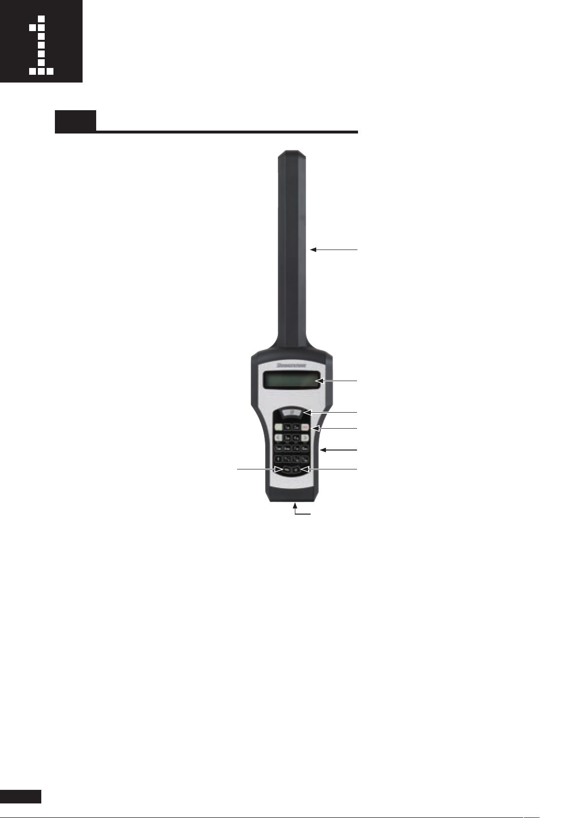
1-1 Part names and functions
Antenna
LCD panel
B button
REG panel
Battery cover (back)
Power switch
PC connector
(Also used as depth gauge connector)
Antenna : Used to exchange data with sensor mounted inside the tire (rim).
LCD panel : Displays setup menus and
B button : Press when measuring tire pressure and internal temperature.
REG panel : Used to select mode and for character and number key input.
Power switch : Used to turn ON the hand reader power (the power turns off automatically if there is no action
for approximately 3 minutes).
LCD backlight switch : Used to turn on the LCD panel backlight (the LCD backlight turns off automatically if there is no
action for approximately 15 seconds).
Battery cover : Remove the battery cover when replacing batteries.
PC connector : Connect the included connection cable to transfer saved data to PC.
Also used to connect
measurement results.
depth gauge (option).
LCD backlight switch
8
Page 10
1-2 Replacing batteries
S E L E C T M E N U L B
1 R E G 2 M E S 3 O B
S E L E C T M E N U
B A T T E L Y A L A R M
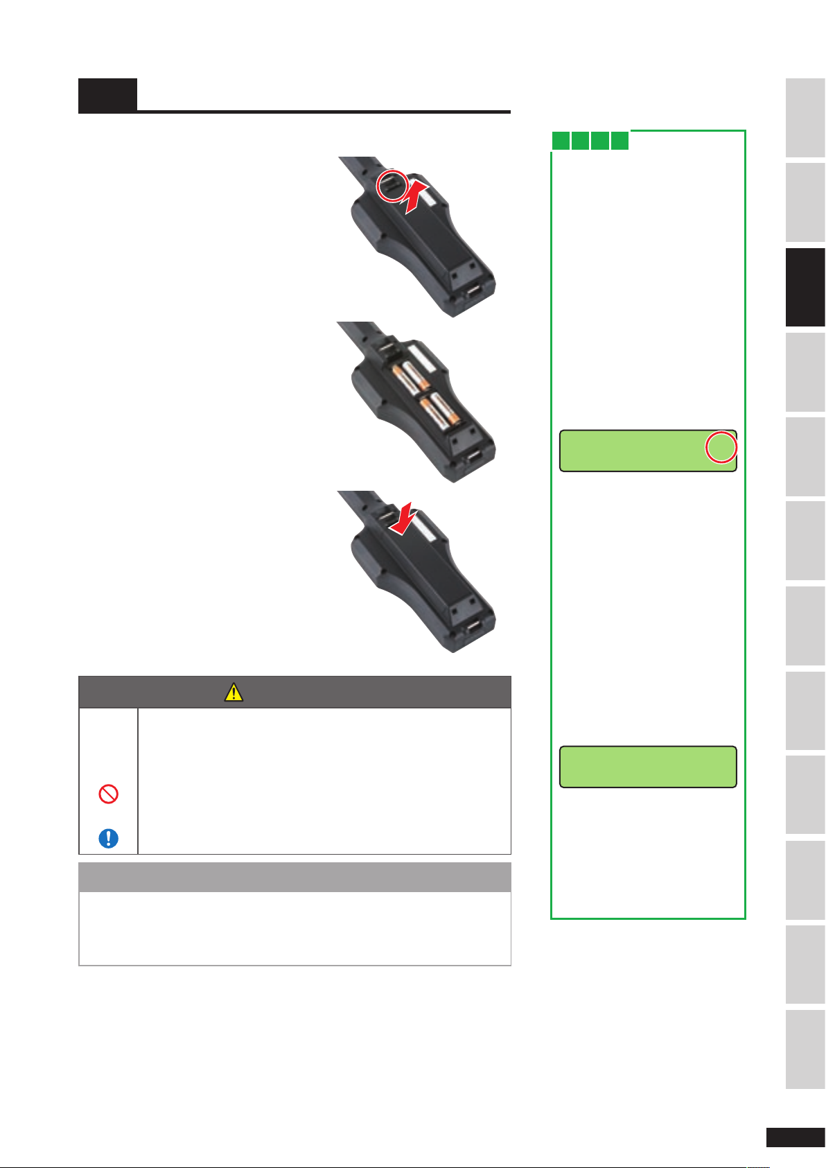
Installing batteries
Pull out the battery cover while pressing
1.
the battery cover tab.
Set four AAA batteries in the battery box
2.
with p ositive and negative poles set
correctly.
Set the battery cover back and close it
3.
securely.
W h e n
You want know when to
replace batteries
The hand reader has a function
to monitor the battery voltage.
When th e vo ltage is l ow, a
ba tter y volta ge low warning
appears on the LCD panel.
The hand reader can still be
u s e d w i t h t h i s w ar n i n g
disp l aye d , b u t repl a ce t h e
batteries promptly according to
the p roc edure de scr ibe d in
s e c t i o n " 1 - 2 R e p l a c i n g
batteries".
Battery voltage low warning
T h i s b a tte r y v o l ta g e l o w
warning disappears when the
Panel screen is switched. Be
careful not to overlook it.
It will reappear when the power
is turned back on.
SAFETY PRECAUTIONS INTRODUCTIONBASIC OPERATIONMES modeREG modeVIEWING SAVED DATA
PART NAMES & FUNCTIONS
C A U T I O N
Failing to observe the following warnings may cause the battery
to leak or heat due to short circuit or charging and cause it to
burst or inflict burns.
• Do not throw batteries in fire, heat it, or disassemble.
• Do not mix new and old batteries or batteries of different
manufacturer.
• Make sure the positive and negative poles correct.
N O T E
• Use only specified battery. You may damage the hand reader if you use
other batteries.
• Check that the battery voltage is sufficient before using. Carry spare
batteries if necessary.
If you continue to use the hand
reader with the battery voltage
low war nin g d isp layed , the
voltage will continue to drop
and batter y voltage alarm will
appear on the LCD panel.
Battery voltage alarm
If you continue to use the hand
reader under this condition, you
may not be able to save the
measured da ta . Replace the
batteries immediately.
TRANSFERRING SAVED DATA
APPENDIXTROUBLESHOOTINGSERVICE & REPAIRINDEX
9
Page 11
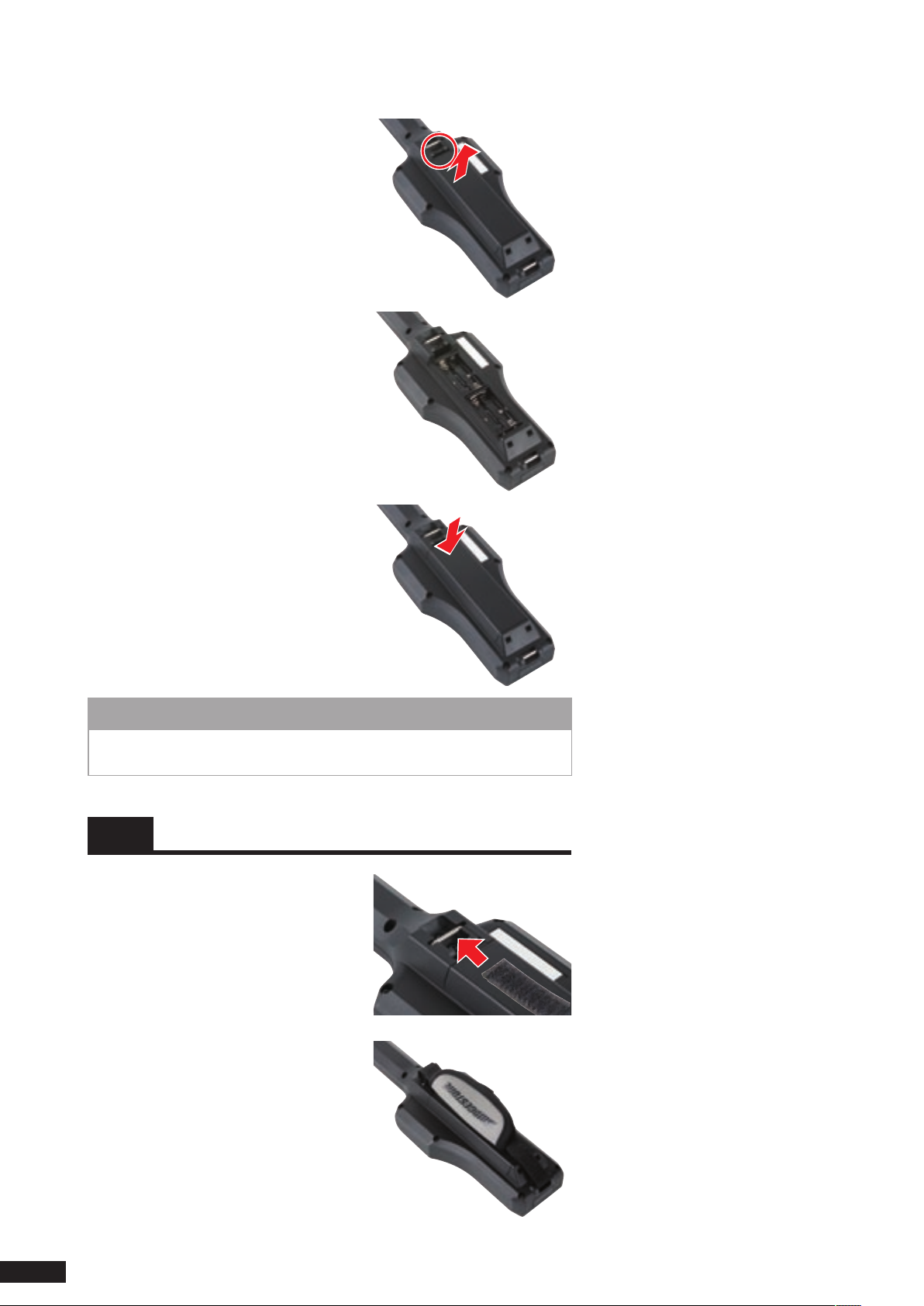
Removing the batteries
Pull out the battery cover while pressing
1.
the battery cover tab.
Remove the batteries.
2.
Set the battery cover back and close it
3.
securely.
N O T E
Be sure to turn off the power before removing the battery. Otherwise, you
may damage the hand reader.
1-3
With the Velcro side of the strap facing
1.
up, pass the strap through the fastener
at the back of the hand reader.
Bend the end of the strap and fasten
2.
with Velcro.
Fasten the other end of the strap in the
3.
same manner.
Installing/removing the strap
(option)
10
Page 12
Basic Operation
T / B H A N D R E A D R
V e r 3 . 0 R e v A
S E L E C T M E N U
1 R E G 2 M E S 3 O B
This chapter describes the basic operation of the hand reader.
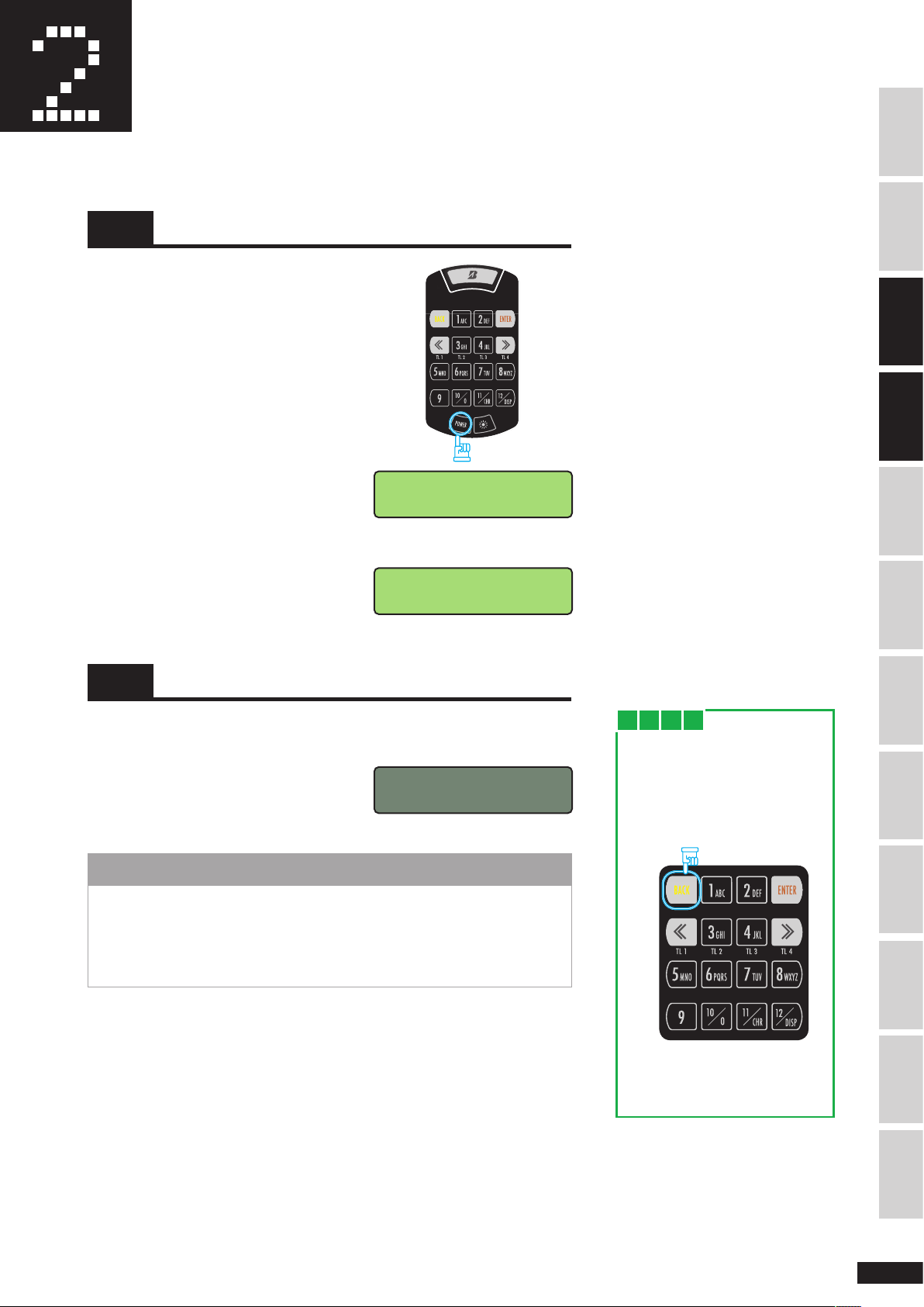
2-1 Power ON
C heck that t he batter y is in sta lle d
1.
properly and turn on the power switch.
The power turns on and the software
2.
version appears on the LCD panel (for 2
seconds).
Select Menu screen appears.
The
3.
2-2 Power OFF
Press
Software Version
Display screen
Select Menu screen
SAFETY PRECAUTIONS INTRODUCTIONMES modeREG modeVIEWING SAVED DATA
PART NAMES & FUNCTIONS
BASIC OPERATION
The power turns off automatically if there is no action for approximately 3
1.
minutes.
The Display screen goes out when the
2.
power is turned off.
N O T E
• The power will not go off while transferring data to PC or while erasing
data.
• If the power goes off while in REG mode, the information registered until
the power goes off is saved.
• There is no power off switch.
W h e n
You get lost during
operation
1. Press the
the S e l ect M e nu s c r e en
appears.
Press
2. W h e n t h e S e l e c t Me n u
screen appears, repeat the
operation from the beginning.
[BACK]
key until
TRANSFERRING SAVED DATA
APPENDIXTROUBLESHOOTINGSERVICE & REPAIRINDEX
11
Page 13
2-3 Turning on the backlight
S E L E C T M E N U
1 R E G 2 M E S 3 O B
S E L E C T M E N U
1 R E G 2 M E S 3 O B
S E L E C T M E N U
1 R E G 2 M E S 3 O B
S E L E C T M E N U
1 R E G 2 M E S 3 O B
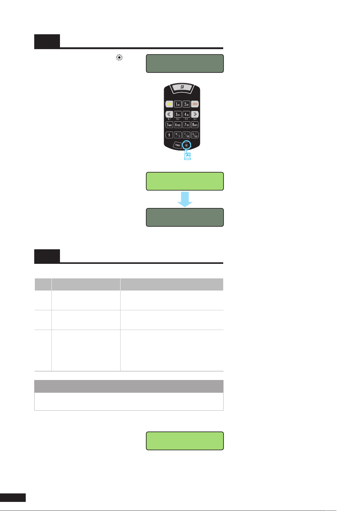
Press the LCD backlight switch ( ).
1.
The LCD panel backlight turns on.
2.
Approximately 15 seconds later
The LCD backlight turns off automatically
3.
if there is no action for approximately 15
seconds.
Press
2-4 Selecting operation mode
There are three operation modes.
No. Operation Mode Description
1 REG mode (Register)
2 MES mode (Measure)
3 OB mode (On-board)
• Do not use 3., OB mode for the Hand Reader type. SET mode is for use
with the On-board type and will affect the life of the sensor.
This is the mode to save the measured
data in hand reader memory.
This is the mode to measure without
saving the data.
This is the mode to set the sensor when
usi ng the ti re- pre s sur e m onit ori n g
system as the On-bard type.
This mo de is n ot used for the Hand
Reader type.
N O T E
Press the POWER switch to turn on the
1.
power.
Check that the
12
SELECT Menu appears.
Select Menu screen
Page 14
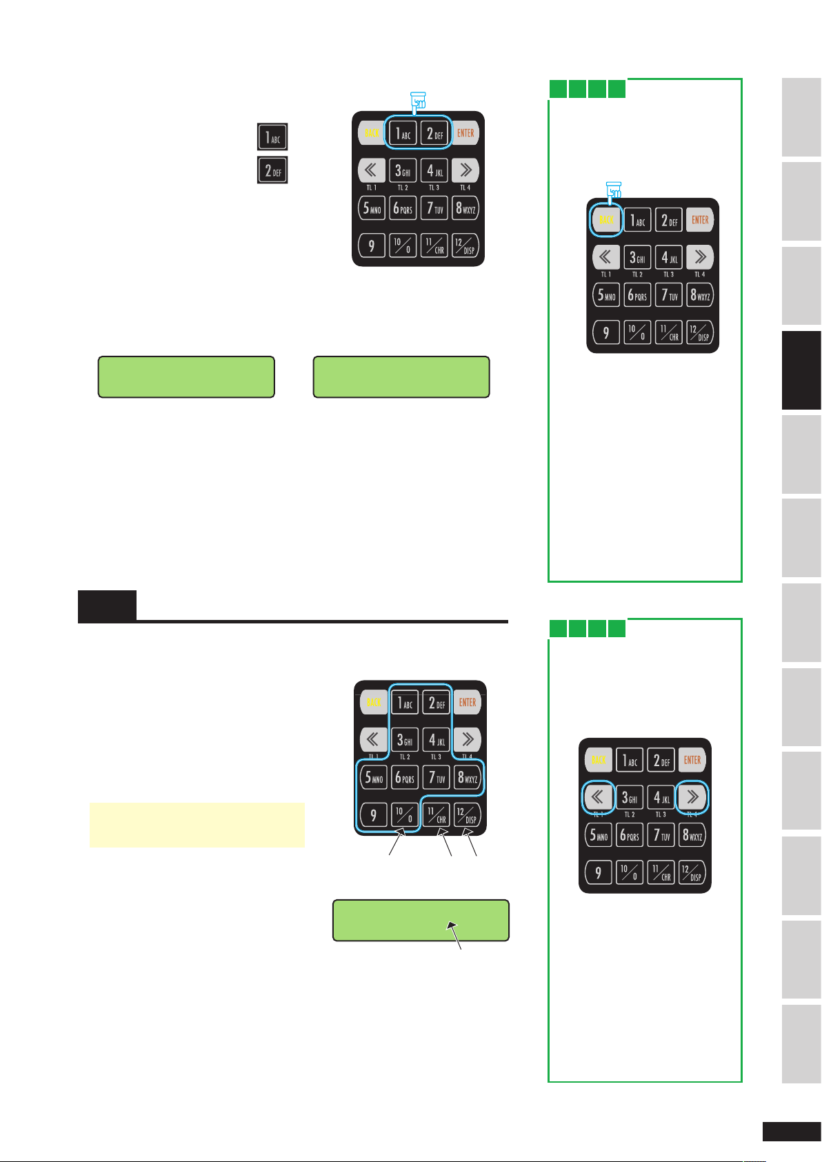
Enter the number of the desired mode
D A T E = 0 6 0 5 2 3
U S E R = P Q R
-
M E S M O D E
R E A D Y
D A T E = 0 6 0 5 2 3
U S E R = P Q R
-
2.
with the number key.
REG mode ..................................
MES mode ..................................
When you enter the number, the scr een of the corresponding mode
3.
appears.
When you select REG mode When you select MES mode
Date, Customer No. Input screen
Pre ss the 1 or 2 key to se lec t the
desired mode.
MES mode Input Wait screen
W h e n
You entered the wrong
operation mode number
1. Press the [BACK] key until the
Select Menu screen appears.
Press
2. Press the correct key when
the S e l ect M e nu s c r e en
appears.
You want to return to
Select Menu screen
When you want t o return to
Select M e n u sc r e e n aft e r
selecting each mode, press the
[B ACK]
Menu screen appears.
key until t he Sel ec t
SAFETY PRECAUTIONS INTRODUCTION
PART NAMES & FUNCTIONS
MES modeREG modeVIEWING SAVED DATA
2-5 Entering numbers
Enter the numbers one by one using the number keys on the REG panel to
enter date, customer no., or vehicle no.
P r ess the nu m b e r k ey t o e n t e r a
1.
number.
To enter 1 to 9:
Press the corresponding
number key.
To enter 0:
• The
used.
When you enter a number, the cursor
2.
moves automatically to the next digit.
Continue with the input of the next
3.
number.
Press the
and
[11]
[12]
key
[10/0]
cannot be
key.
(Enter 0)
Not used for
number input
Cursor
W h e n
You want to correct the
entered number
Move the cursor to the desired
location with the
and enter the correct number.
[«]
or
[»]
You want to move to top
or bottom line
When you enter up to the end
of the to p l ine, th e c urso r
autom ati cally m oves to the
beginning of the bottom line.
To move between the top and
bottom line when modifying,
move the cursor with
key.
[«]
or
key
[»]
TRANSFERRING SAVED DATA
APPENDIXTROUBLESHOOTINGSERVICE & REPAIRINDEX BASIC OPERATION
13
Page 15
V E H I C L E N O ?
V - N O =
-
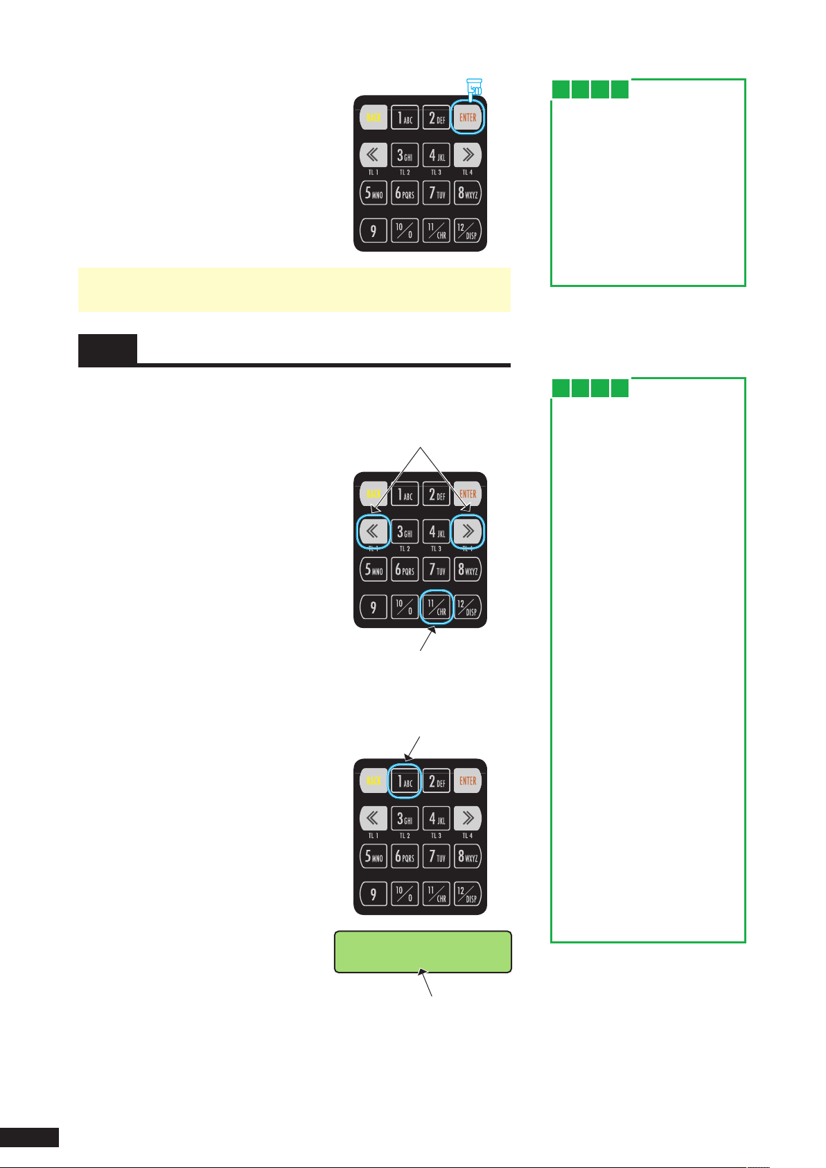
After you finish en te ri ng , press t he
4.
[ENTER]
• If an invalid number is entered, a long alarm (1.5 seconds) sounds when
you press the
key to confirm the entry.
[ENTER]
key. Enter the correct number.
Press
2-6 Entering characters
W h e n
W h e n
You want to move the
cursor to the previous
digit
Move the cursor with
Do not use the
move the cursor to the previous
digi t . When yo u p r e ss t h e
[BACK]
returns to the Previous Mode
screen.
[BACK]
key, the LCD pane l
[«]
key.
key to
Enter the character using the number keys on the REG panel to enter
characters for customer no. and vehicle no.
1. Move the cursor to the desired location
with the
2. Pr ess the
character input mode.
Then you can enter characters with the
number keys.
Press the number key printed with the
3.
desired character.
The alphabets printed on the key are
displayed in order each time you press
the key.
[«]
or
key.
[»]
k ey to cha nge t o
[CH R]
Move the cursor left or right.
Switching between alphabet and
number input.
Rot ates as A, B, C,
A... each time key is
pressed.
W h e n
W h e n
You want to continue
entering character in the
next digit
Press the number key printed
with the desired character to
enter the character.
The character is entered in the
next digit.
To enter the character printed
on the same number key in the
ne xt d ig it ( such as ent ering
"AB"):
1. Enter the first character.
2. Move the cursor to the next
digit with
3. Enter the character with the
same number key.
Example) Entering "AB"
1. Pr es s th e
enter "A".
2. Move the cursor to the next
digit with
3. Press the
enter "B".
key.
[»]
key on ce t o
[1]
key.
[»]
key twice to
[1]
Example) Entering "C"
Press the
14
[1]
key three times.
Cursor
You want to return to
number input mode
Press the
changes to number input mode.
key. The mode
[CHR]
Page 16
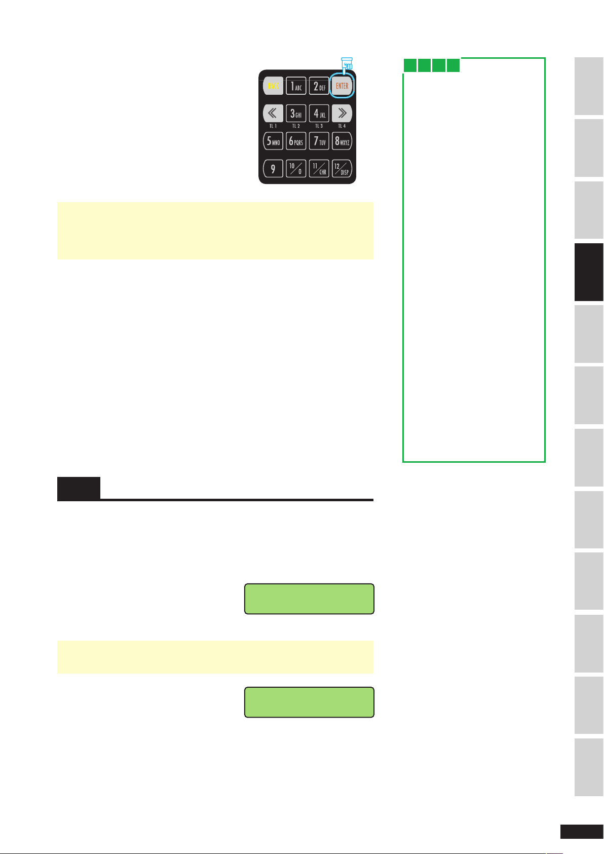
After you finish en te ri ng , press t he
P U S H T I R E
P O S I T I O N B U T T O N !
V N = E F 5 2 5 3 T P = 0 8
R E S = 5 6 7 R E A D Y !
4.
[ENTER]
character.
key to confirm the entered
Press
W h e n
You want to move to top
or bottom line
When you enter up to the end
of the to p l ine, th e c urso r
autom ati cally m oves to the
beginning of the bottom line.
To move between the top and
bottom line when modifying,
move the cursor with
key.
[«]
or
[»]
SAFETY PRECAUTIONS INTRODUCTION
• Depending on the input item, you may not need to enter all digits, but
you cannot use space between characters.
If there is a space between characters, a long alarm (1.5 seconds) sounds
when you press the
[ENTER]
key.
2-7 Entering the tire position
You want to erase a space
To e r a se spa c e b e t wee n
characters:
1. Pre ss t he
return to the previous menu.
2. Reenter the characters from
the beginning.
You c an al so ove r w rit e the
space with a character to erase
the space as follows:
Example)
To erase the space in "AA BB"
1. Press the
move the cursor to the space.
2. Pre ss any key to over write
the space with a character.
[ B ACK ]
[«]
ke y t o
key twice to
PART NAMES & FUNCTIONS
MES modeREG modeVIEWING SAVED DATA
The arrangement of the number keys on the control panel corresponds to the
installed position of the tires on the vehicle. The tire position depends on the
type of vehicle (truck (tractor), bus, or trailer), number of tires, and axle
arrangement. Enter the tire position by number according to the relationship
between tire position and number keys show on page 15.
Press the number key corresponding to
1.
the d esire d tir e pos iti on in the T ire
Position Input screen.
Tire Position Input screen
• If an invalid tire position is entered, a long alarm (1.5 seconds) is sounded.
Enter the correct tire position.
When you enter the tire position, the
2.
Information Input Wait screen appears.
Information Input Wait screen
TRANSFERRING SAVED DATA
APPENDIXTROUBLESHOOTINGSERVICE & REPAIRINDEX BASIC OPERATION
15
 Loading...