

Page 1
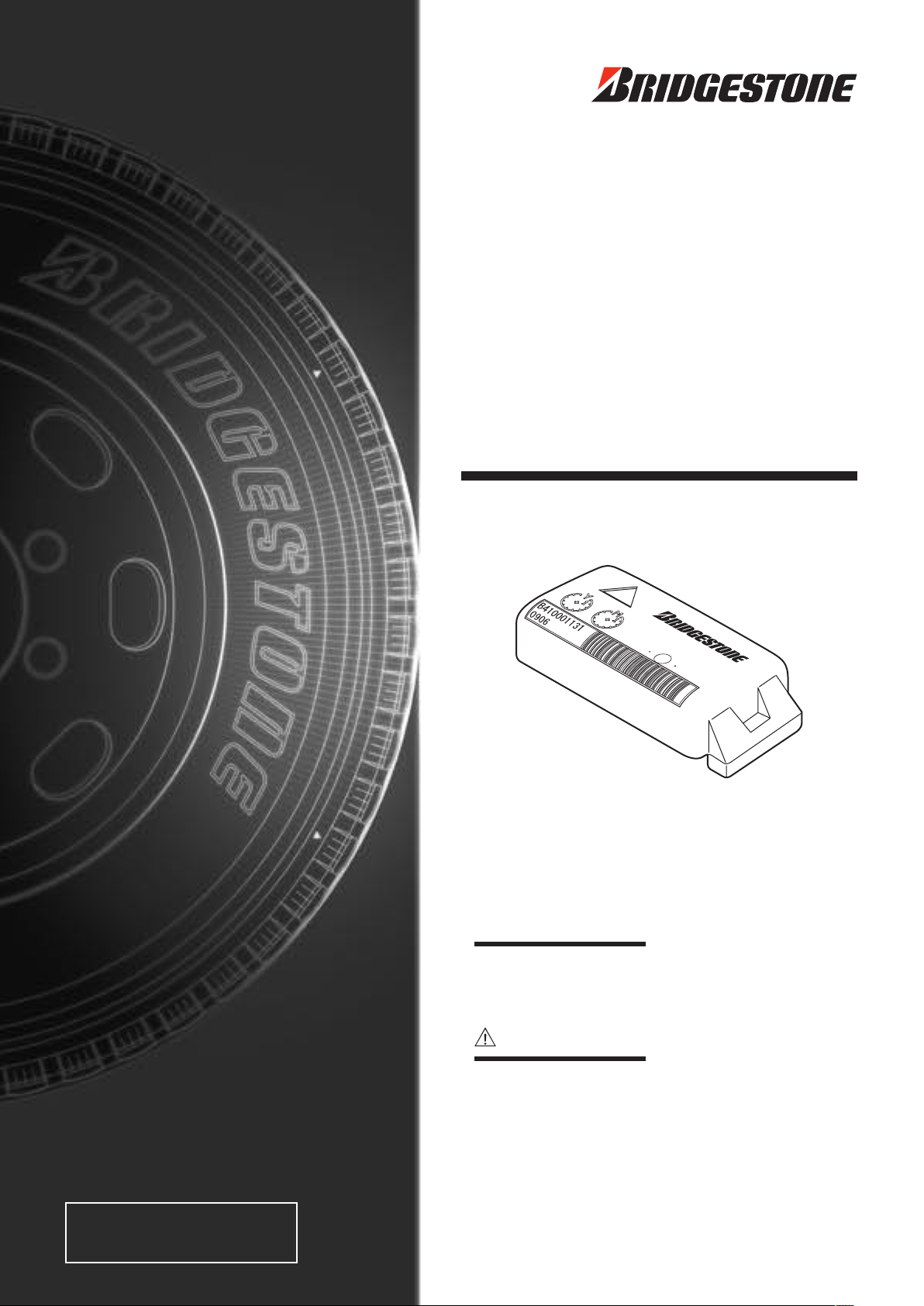
Tire-Pressure Monitoring System
Sensor
Operation Guide
For truck and bus
For use only in Europe (model:B422) or
U.S.A. (model:B421)
What is a Tire-Pressure Monitoring System
Ti re -p re ss ur e mo ni to ri ng s ys te m is a n ad va nc ed s ys te m th at
measures the tire pressure and temperature with sensors mounted
inside the tire and enables vehicle management using the measured
data.
Notice to user
・
Th is product is d es ig ne d exclusively f or t ru ck s and buses.
Supported rim size is from 16 to 22.5 inches.
・
This product has two design for use within Europe and USA. It
cannot be used other country du e t o difference in radio wav e
regulations. Attention for product model number.
For Europe ...... model B422
For USA .......... model B421
・
Techn ica l knowle dge is nece ssa ry for sens or installa tion and
removal. Contact shops employing tire mechanic for installation
and removal.
・
Be sure to read and understand the content of the operation guide
before installing or removing.
・
Keep this guide in a safe place and refer to it as necessary.
?
Page 2

Page 3
Introduction
Tire-Pressure Monitoring System
For truck and bus
For use only in Europe (model:B4
22) or
U.S.A. (model:B4
21)
Sensor
Operation Guide
Notice to user
What is a Tire-Pressure Monitoring System?
Tire-pressu re m onit orin g sy stem is an a dvan ced syst em t hat
measures the tire pressure and temperature with senso rs mounted
inside the tire and enables vehicle management using the measured
data.
・
This pr oduc t i s de sign ed e xclu sive ly f or truc ks a nd b uses .
Supported rim size is from 16 to 22.5 inches.
・
This product h as two de sign for use wit hin Europ e and US A. It
cannot be used ot her cou ntry d ue to differ ence in radio wave
regulations. Attention for product model number.
For Europe......model B4
22
For USA..........model B4
21
・
Technical knowl edge i s nec essary for sensor insta llati on and
removal. Contact shops employi ng tire mec hanic for i nstallation
and removal.
・
Be sure to read and understand the content of the operation guide
before installing or removing.
・
Keep this guide in a safe place and refer to it as necessary.
This guide describes how to use the tire pressure monitoring system sensor (referred hereafter as "this product" or
"sensor") designed exclusively for trucks and buses. Please read and understand the content before using.
NOTE
Installation of this product requires knowledge of vehicle safety and tires. Installation should be performed by a
person with such experience.
About This Product
• By installing this product inside the tire (rim), it can measure the pressure and internal temperature and send the data
by radio wave.
• A separate hand reader is necessar y to read the data after installing this product. Hand reader can be purchased
separately from your dealer.
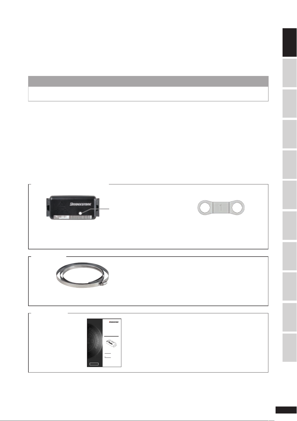
Package Content
Check that the following items are included in the package.
Items included in the sensor package
Mark color for location
For Europe: Model No.B422
Color: green
Sensor x 6 to 12
(depend on the number of tires)
For USA: Model No.B421
Color: blue
Valve mark x 6 to 12
(depend on the number of tires)
SAFETY PRECAUTIONSSENSOR INSTALLATIONMOUNTING TIRE ON RIMREMOVE THE SENSOR
TRANSPORTATION,
STORAGE & DISPOSAL
TROUBLESHOOTINGSERVICE & REPAIRSPECIFICATIONINDEXSENSOR WARRANTY INTRODUCTION
Mounting band
Mounting band (specified rim size) x 6 to 12
(depend on the number of tires)
Operation Guide
* Number of packages depend on the part number.
* Six mounting bands are contained in one box. The
remainder are packaged separately.
* The operation guide can be obtained separately from
your dealer. It is not included with the product.
1
Page 4
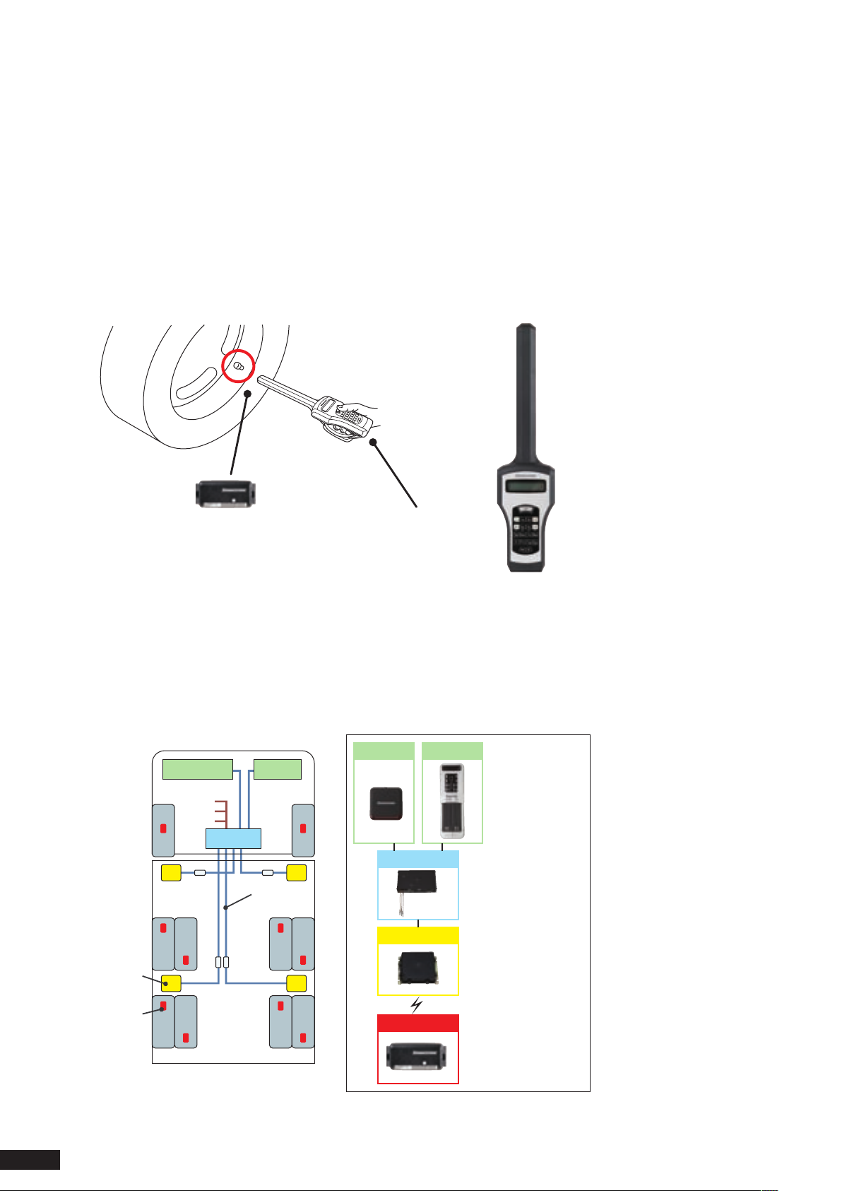
About Tire-Pressure Monitoring System
Receiver
Sensor
Example of installing
4 receivers and 10 sensors
Receiver
Cable
Vehicle power supply
▪BAT
▪IGN
▪GND
ECU
Display
Warning lamp
Warning lamp
Display
ECU
Receiver
Sensor
Install on dashboard
Install inside cabi
n
Install on vehicle or fram
e
Install inside tire (rim
)
The tire-pressure monitoring system (hereafter referred to as "system" or "this system") is a system that monitors the tire
pressure and temperature using
This system is available as "Hand Reader Type" and "On-Board Type". Purchase the product that is appropriate for your
intended use.
Hand reader type
This system receives the radio wave from the sensor with a portable hand reader.
The radio wave from the sensor is received with the vehicle stopped. It cannot be used when moving.
<Equipment Configuration>
sensors mounted inside tires (rim).
Sensor Hand reader
On-board type
This system measure and monitors the radio wave from the sensor with a display and warning lamp mounted on the
dashboard.
When there is a tire problem, the display and warning lamps on the dashboard emit alarms to notify the driver. The tire
status can be monitored while moving.
<Equipment Configuration>
2
Page 5

Operation Guide Combination
The following operation guides must be obtained depending on whether your system is a Hand reader type or On-board
type. Read the guide appropriate for your system.
Guide
Tire-Pressure Monitoring System
Sensor Operation Guide
(this document)
Tire-Pressure Monitoring System
On-Board Type Operation Guide
Tire-Pressure Monitoring System
Display Operation Guide
Tire-Pressure Monitoring System
Hand Reader Type Operation Guide
• This operation guide uses photographs to describe the installation procedure, but the supported rims and installation
method are not limited to those in the photograph.
• Unauthorized duplication or reprint of any part of this operation guide or in its entirety is prohibited.
• If this operation guide becomes smudged and unreadable, obtain a new one from your dealer.
• Contact your dealer if there is any misprint or missing page and for questions about its content.
Hand reader
type
On-board
type
Content
Describes sensor installation, rim installation
and removal, and precautions
Describes the installation, wiring, system setup,
and precautions of receiver, display, warning
lamp, and ECU
Describes the display operation method and
precautions
Describes the hand reader operation method
and precautions
Warranty and Disclaimer
Warranty
SAFETY PRECAUTIONSSENSOR INSTALLATIONMOUNTING TIRE ON RIMREMOVE THE SENSOR
TRANSPORTATION,
STORAGE & DISPOSAL
• This is a system that measures the tire pressure and temperature using sensors mounted inside tires (rim).
Bridgestone shall not be liable for any damage resulting from use of this product for other purposes or in combination
with other manufacturer's product.
• Do not disassemble or modify this product. Bridgestone shall not be liable for any damage resulting from disassembly
or modification of this product.
• Read the operation guide carefully and understand its content before using this system. Bridgestone shall not be liable
for any damage resulting from misuse of this product.
• Warranty period is 1 year from the date of purchase. Refer to the "Sensor Warranty Policy" (page 27) for the details of
the warranty.
Product specification limitations
• This product have two design for use within Europe and USA. It cannot be used other country due to difference in
radio wave regulations. Attention for product model number.
For Europe : model B422
For USA : model B421
• This system has no function to maintain the status of the tire itself in good condition.
• When using the On-Board Type, the radio wave from the sensor may be temporarily interrupted depending on whether
the vehicle is stopped, presence of radio frequency interference, or position of the tires. In such case, the display and
warning lamps may be temporarily disabled.
• Be sure to measure the tire pressure with a normal pressure gauge during periodic maintenance and when
refueling. Compare those results with the tire pressure displayed by this system and check that the system is
functioning properly.
TROUBLESHOOTINGSERVICE & REPAIRSPECIFICATIONINDEXSENSOR WARRANTY INTRODUCTION
3
Page 6

Contents
Introduction .................................................................... 1
About This Product ..................................................
Package Content .....................................................
About Tire-Pressure Monitoring System .................
Operation Guide Combination ................................ 3
Warranty and Disclaimer .........................................
1
1
2
3
Safety Precautions ..................................................
1. Sensor Installation .......................................................
1-1
Marks and label .......................................... 8
1-2
Installation flow .......................................... 8
1-3
Required tools ........................................... 9
1-4
Mark the sensor usage start date .............. 9
1-5
Attach mounting band to rim .................... 10
1-6
Install the sensor ..................................... 10
1-7
Attach the valve mark ............................... 12
1-8
Enter in check sheet ................................. 12
1-9
For super single tire ................................. 12
2. Mounting tire on rim and Operation Verification ....... 13
2-1 Required tools ......................................... 13
2-2 Mounting tire on rim ............................... 13
2-3 Install the tire on the axle ......................... 15
3. Remove the Sensor ..................................................
3-1 Sensor removal flow ................................ 16
3-2 Required tools .......................................... 16
3-3 Remove the rim ........................................ 16
3-4 Remove the sensor from the rim ............. 18
4. Sensor Transportation, Storage, and Disposal .......... 19
4-1 Precaution during transportation .............. 19
4-2 Precaution during storage ........................ 19
4-3 Precaution during disposal ....................... 19
16
5
8
5. Troubleshooting .........................................................
5-1 No response from the sensor ................. 20
5-2 When the sensor is damaged .................. 20
6. Service and Repair ....................................................
6-1 Requesting repair ..................................... 21
6-2 Periodic Maintenance ............................... 22
6-3 Disposal of the product ............................ 22
6-4 Contact ..................................................... 22
7. Specification ..............................................................
Index .............................................................................
Sensor Warranty ...........................................................
20
21
23
24
25
4
Page 7

Safety Precautions
Warning symbols
This guide uses the following symbols to describe items that you must observe in order to use the hand reader safely.
Read and observe these items carefully.
WARNING
CAUTION
NOTE
Pictograms
Indicates item that must be observed.
Indicates action that is prohibited.
Indicates danger of bodily harm.
Failure to observe this item may result in death or severe injury.
Failure to observe this item may result in minor injury or property damage.
Failure to observe this item may result in damage to the product.
This also describes items that you should keep in mind.
1. Sensor handling
WARNING
Failure to observe the following warning items may result in serious traffic accident due to tire damage or erroneous
air pressure detection.
• This product is designed exclusively for trucks and buses.
Supported rim size is from 16 to 22.5 inches.
Do not use it on other vehicles or for other purpose.
• This product have two design for use within Europe and USA. It cannot be used other country due to difference in
radio wave regulations. Attention for product model number.
For Europe : model H212
For USA : model H211
• Do not disassemble, modify, or repair the sensor.
This can cause sensor dropout, battery heating or ignition.
Note that the sensor battery is not replaceable. When the battery life has expired, assume that the life of the entire
product including electrical component has expired.
• Do not leave sensor with expired battery inside the tire for an extended period.
• Be sure to measure the tire pressure with a normal pressure gauge during periodic maintenance. Compare those
results with the tire pressure displayed by this system and check that the system is functioning properly.
SENSOR INSTALLATIONMOUNTING TIRE ON RIMREMOVE THE SENSOR
TRANSPORTATION,
STORAGE & DISPOSAL
TROUBLESHOOTINGSERVICE & REPAIRSPECIFICATIONINDEXSENSOR WARRANTY INTRODUCTIONSAFETY PRECAUTIONS
5
Page 8

2. About general sensor installation and removal
WARNING
Failure to observe the following warning items may result in serious traffic accident due to tire damage or detection
of erroneous
• Install or uninstall the sensor at a tire shop.
• Refer to the instructions in the operation guide when installing or uninstalling the sensor.
• Use genuine mounting band to secure the sensor. Using unauthorized band can cause the band to break during
vehicle movement resulting in rim or tire damage.
• Be sure to use new mounting band matching the wheel diameter and rim size. Using mounting band that is too
long, too short, or previously used can cause the sensor or band to drop out during vehicle movement resulting in
rim or tire damage.
• If the width of the well at the center of the rim is extremely narrow causing the sensor to touch the wall of the well
or if the well is extremely shallow causing the sensor to protrude from the well, contact your authorized dealer or
Bridgestone customer service and check that the sensor can be installed beforehand.
• Be sure to attach a white plastic "valve mark" on the valve of the tire with sensor installed.
• Be careful not to damage the sensor or the mounting band when replacing the tire. The mounting band can become
loose and drop out during motion when it comes in contact with tire lever or tire changer. Tires with white plastic
"valve mark" on the valve are tires with sensor installed near the valve. Be careful with their handling.
• Normal "mounting tire on rim" and "removing tire from rim" involves equipment such as tire changer and can cause
tire damage. Observe the general precautions for "mounting tire on rim" and "de-mounting tire on rim" described in
the equipment manual.
• If the tire is improperly rimmed, the tire can burst and fly apart when inflating. Be sure to inflate the tire inside a
safety enclosure.
• This guide describes the precautions during installation of this product, but it is not possible to assume and
describe all hazards. Be very careful when performing these tasks.
air pressure.
6
Page 9
Notices for using in USA
This device complies with Part 15 of the FCC Rules and IC RSS-Gen. Operation is subject to the following two conditions:
(1) This device may not cause harmful interference, and (2) this device must accept any interference received, including
interference that may cause undesired operation.
This equipment has been tested and found to comply with the limits for a Class B digital device, pursuant to Part 15 of
the FCC Rules and IC RSS-Gen.
These limits are designed to provide reasonable protection against harmful interference in a residential installation. This
equipment generates use and can radiate radio frequency energy and, if not installed and used in accordance with
instructions, may cause harmful interference to radio communications. However, there is no guarantee that interference
will not occur in a particular installation. If this equipment does cause harmful interference to radio or television
reception, which can be determined by turning the equipment off and on, the user is encouraged to correct the
interference by one or more of the following measures:
- Reorient or relocate the receiving antenna.
- Increase the separation between the equipment and receiver.
- Connect the equipment into an outlet on a circuit different from that to which the receiver is connected.
- Consult the dealer or an experienced radio/TV technician for help.
WARNING
Changes or modifications not expressly approved by the manufacturer for compliance could void the user’s
authority to operate the equipment.
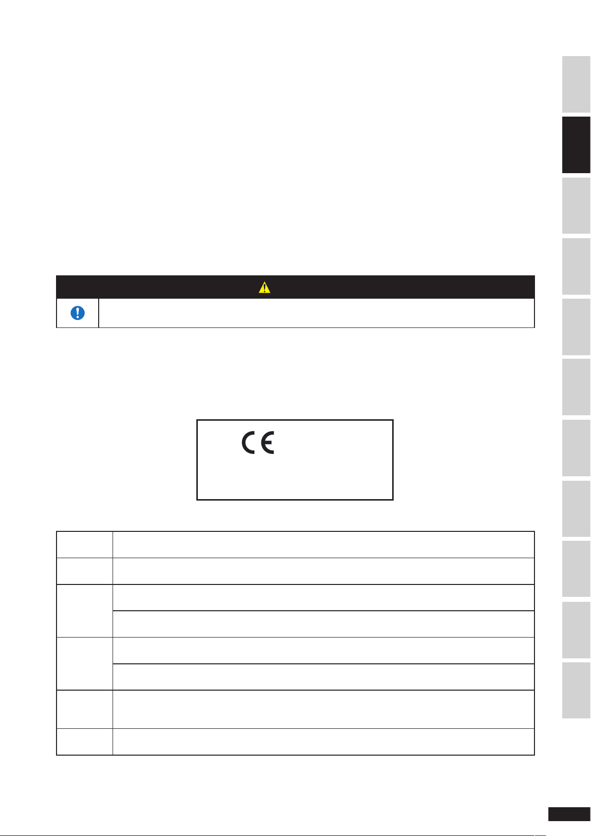
WARNING for using in Europe
INTRODUCTIONSENSOR INSTALLATIONMOUNTING TIRE ON RIMREMOVE THE SENSOR
We, the manufacturer (BRIDGESTONE CORPORATION) hereby declare that this equipment (TPMS), model B422 is in
compliance with the essential equirements and other relevant provisions of Directive 1999/5/EC.
0891
BRIDGESTONE CORPORATION
Model No.: B422
TCAM agreed that it is sufficient to add the following statement as part of the user information:
English
Finnish
Dutch
French
Swedish
Danish
Hereby,
essential requirements and other relevant provisions of Directive 1999/5/EC.
(BRIDGESTONE CORPORATION) vakuuttaa täten että (SENSOR:B422) tyyppinen laite on direktiivin
1999/5/EY oleellisten vaatimusten ja sitä koskevien direktiivin muiden ehtojen mukainen.
Hierbij verklaart (BRIDGESTONE CORPORATION) dat het toestel (SENSOR:B422) in overeenstemming
is met de essentiële eisen en de andere relevante bepalingen van richtlijn 1999/5/EG
Bij deze verklaart (BRIDGESTONE CORPORATION) dat deze (SENSOR:B422) voldoet aan de
essentiële eisen en aan de overige relevante bepalingen van Richtlijn 1999/5/EC.
Par la présente (BRIDGESTONE CORPORATION) déclare que (SENSOR:B422) est conforme aux
exigences essentielles et aux autres dispositions pertinentes de la directive 1999/5/CE
Par la présente, (BRIDGESTONE CORPORATION) déclare que ce (SENSOR:B422) est conforme aux
exigences essentielles et aux autres dispositions de la directive 1999/5/CE qui lui sont applicables
Härmed intygar (BRIDGESTONE CORPORATION) att denna (SENSOR:B422) står I överensstämmelse
med de väsentliga egenskapskrav och övriga relevanta bestämmelser som framgår av direktiv 1999/5/
EG.
Undertegnede (BRIDGESTONE CORPORATION) erklærer herved, at følgende udstyr (SENSOR:B422)
overholder de væsentlige krav og øvrige relevante krav i direktiv 1999/5/EF
(BRIDGESTONE CORPORATION), declares that this (SENSOR:B422) is in compliance with the
TRANSPORTATION,
STORAGE & DISPOSAL
TROUBLESHOOTINGSERVICE & REPAIRSPECIFICATIONINDEXSENSOR WARRANTY SAFETY PRECAUTIONS
7
Page 10

German
Greek
Italian
Spanish
Portuguese
Czech
Estonia
Latvia
Lithuania
Hungary
Malta
Poland
Slovenia
Slovakia
Bulgaria
Romania
Turkey
Hiermit erklärt (BRIDGESTONE CORPORATION), dass sich dieser/diese/dieses (SENSOR:B422) in
Übereinstimmung mit den grundlegenden Anforderungen und den anderen relevanten Vorschriften der
Richtlinie 1999/5/EG befindet”. (BMWi)
Hiermit erklärt (BRIDGESTONE CORPORATION) die Übereinstimmung des Gerätes (SENSOR:B422)
mit den grundlegenden Anforderungen und den anderen relevanten Festlegungen der Richtlinie 1999/5/
EG. (Wien)
ΜΕ ΤΗΝ ΠΑΡΟΥΣΑ (BRIDGESTONE CORPORATION) ΔΗΛΩΝΕΙ ΟΤΙ (SENSOR:B422)
ΣΥΜΜΟΡΦΩΝΕΤΑΙ
ΟΔΗΓΙΑΣ
1999/5/ΕΚ
ΠΡΟΣ ΤΙΣ ΟΥΣΙΩΔΕΙΣ ΑΠΑΙΤΗΣΕΙΣ ΚΑΙ ΤΙΣ ΛΟΙΠΕΣ ΣΧΕΤΙΚΕΣ ΔΙΑΤΑΞΕΙΣ ΤΗΣ
Con la presente (BRIDGESTONE CORPORATION) dichiara che questo (SENSOR:B422) è conforme ai
requisiti essenziali ed alle altre disposizioni pertinenti stabilite dalla direttiva 1999/5/CE.
Por medio de la presente (BRIDGESTONE CORPORATION) declara que el (SENSOR:B422) cumple
con los requisitos esenciales y cualesquiera otras disposiciones aplicables o exigibles de la Directiva
1999/5/CE
(BRIDGESTONE CORPORATION) declara que este (SENSOR:B422) está conforme com os requisitos
essenciais e outras disposições da Directiva 1999/5/CE.
Společnost (BRIDGESTONE CORPORATION) tímto prohlašuje, že (SENSOR:B422) splňuje základní
požadavky a další příslušné ustanovení Direktivy 1999/5/EC.
Sellega kinnitab (BRIDGESTONE CORPORATION), et see (SENSOR
:B422) vastab direktiivi 1999/5/EC
põhilistele nõudmistele ja muudele asjakohastele määrustele.
Ar šo, (BRIDGESTONE CORPORATION), apstiprina, ka (SENSOR:B422) atbilst Direktīvas 1999/5/EK
galvenajām prasībām un citiem tās nosacījumiem.
Šiuo, (BRIDGESTONE CORPORATION), pareiškia, kad šis (SENSOR
:B422) atitinka pagrindinius
Direktyvos 1999/5/EB reikalavimus ir kitas svarbias nuostatas.
Alulírott, (BRIDGESTONE CORPORATION), kijelenti, hogy a jelen (SENSOR:B422) megfelel az 1999/5/
EC irányelvben meghatározott alapvető követelményeknek és egyéb vonatkozó előírásoknak.
Hawnhekk, (BRIDGESTONE CORPORATION), tiddikjara li (SENSOR
:B422) josserva l-ħtiġijiet essenzjali
u dispożizzjonijiet relevanti oħra tad-Direttiva 1995/5/KE.
(BRIDGESTONE CORPORATION) niniejszym oświadcza, że (SENSOR:B422) spełnia zasadnicze
wymogi oraz inne istotne postanowienia dyrektywy 1999/5/EC.
S tem (BRIDGESTONE CORPORATION) izjavlja, da je ta (SENSOR
:B422) v skladu z osnovnimi
zahtevami in ostalimi ustreznimi predpisi Direktive 1999/5/EC.
Spoločnosť (BRIDGESTONE CORPORATION) týmto vyhlasuje, že (SENSOR:B422) spĺňa základné
požiadavky a ďalšie príslušné ustanovenia Direktívy 1999/5/EC.
С настоящия документ (BRIDGESTONE CORPORATION)
декларира, че (SENSOR:B422) е в
съгласие с основните изисквания и съответните постановления на Директива 1999/5/ЕС.
Prin prezenta, (BRIDGESTONE CORPORATION) declară că acest (SENSOR:B422) este conform cu
cerinţele principale şi cu celelalte prevederi relevante ale Directivei 1999/5/EC.
İşbu belge ile (BRIDGESTONE CORPORATION), bu (SENSOR:B422)’in 1995/5/EC Yönetmeliği esas
gereksinimlerine ve diğer şartlarına uygun olduğunu beyan eder.
8
Page 11
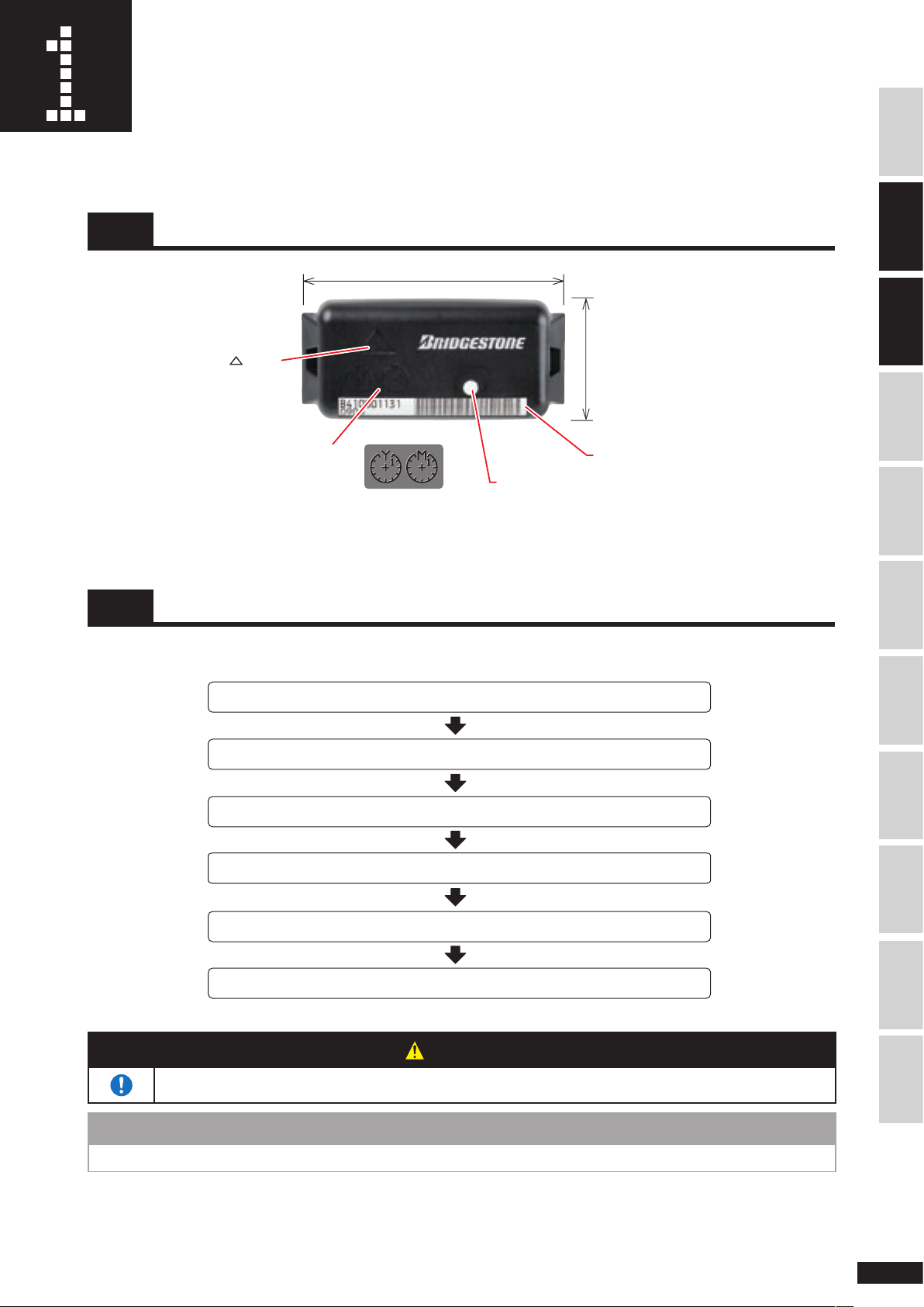
Sensor Installation
Jack up the vehicle
Remove the tire from the axle
Remove the rim
Install the sensor on the rim
Replace the rim
Install the tire on the axle
31mm
66mm
Sensor usage start
date mark
mark
Barcode label
Mark color for location
For Europe:
Model No.B422
Color: green
For USA: Model No.B421
Color: blue
This product is a "band mount sensor" that attaches the sensor to the rim with the included mounting band.
1-1 Marks and label
INTRODUCTIONMOUNTING TIRE ON RIMREMOVE THE SENSOR
1-2 Installation flow
Install the sensor to the rim in the following sequence regardless of the type of tire.
• Sensor installation and removal must be performed a tire shop.
WARNING
TRANSPORTATION,
STORAGE & DISPOSAL
TROUBLESHOOTINGSERVICE & REPAIRSPECIFICATIONINDEXSENSOR WARRANTY SAFETY PRECAUTIONSSENSOR INSTALLATION
• This product is cannot be used on tube tires. The air pressure cannot be measured even if it is installed.
NOTE
9
Page 12
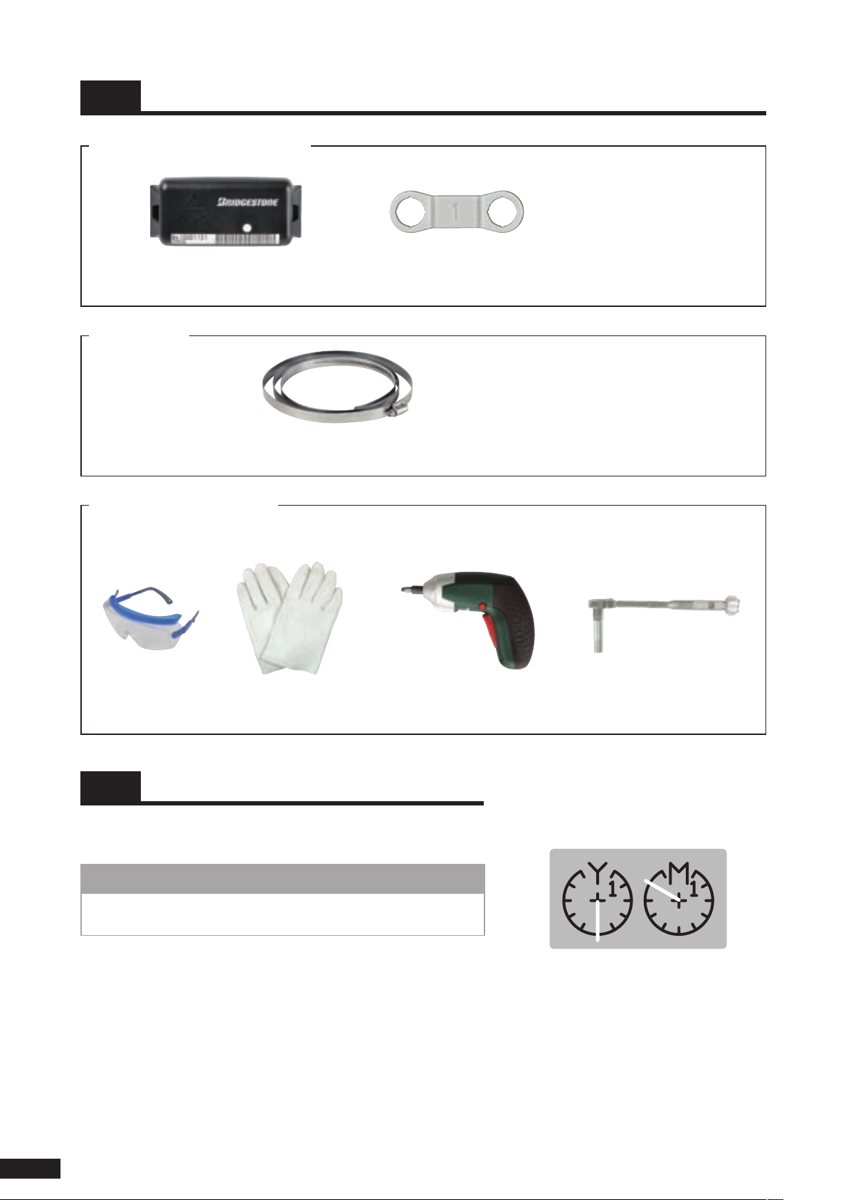
1-3 Required tools
Year
(position6)
Month
(position10)
Items included in the sensor package
Sensor x 6 to 12
(depend on the number of tires)
Mounting band
Mounting band (specified rim size) x 6 to 12
(depend on the number of tires)
Have the following items ready
Have the following safety gears and tools ready.
Valve mark x 6 to 12
(depend on the number of tires)
* Number of packages depend
on the part number.
* Six mounting bands are contained
in one box. T he remai nd er a re
packaged separately.
Protective glasses Power driver
1-4
Use a flat blade driver and enter the date in the sensor usage start
date mark.
Mark the sensor usage start date
Gloves Torque wrench
(flat bit)
NOTE
• If you enter the mark too hard, the sensor's material strength may
be weakened causing it to break during use.
(socket size 8 mm)
Example: Entering Oct. 2006.
10
Page 13
11
SAFETY PRECAUTIONS INTRODUCTIONMOUNTING TIRE ON RIMREMOVE THE SENSOR
TRANSPORTATION,
STORAGE & DISPOSAL
TROUBLESHOOTINGSERVICE & REPAIRSPECIFICATIONINDEXSENSOR WARRANTY SENSOR INSTALLATION
WARNING
• Be sure to use genuine mounting band to secure the sensor. Using unauthorized band can cause the
band to break during vehicle movement. This can cause rim or tire damage resulting in traffic accident or
injury.
• Be sure to use new mounting band matching the wheel diameter and rim size. Using mounting band that
is too long, too short, or previously used can cause the sensor or band to drop out during vehicle
movement. This can cause rim or tire damage resulting in traffic accident or injury.
• Wear protective glasses. The mounting band may break and inure your eyes.
CAUTION
• Wear gloves. The mounting band and fixtures may injure your hand.
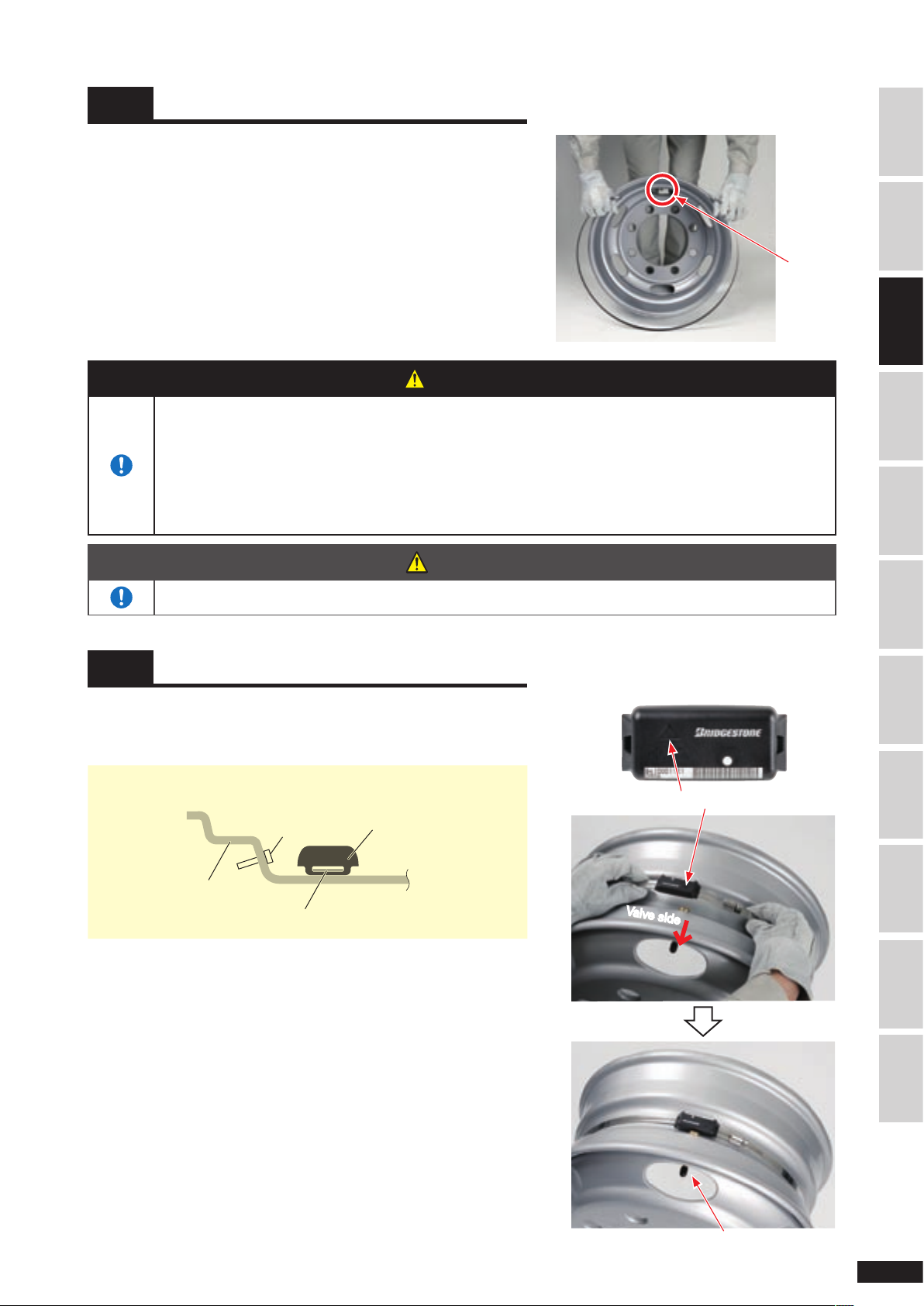
1-5 Attach mounting band to rim
1.
Check that the included mounting band is the same rim size as the
specifi ed wheel diameter. (Rim size is written on the box containing
the mounting band.
2.
Place the rim by your feet with the valve side up and stand on the
disk side.
3.
Hold the fi xture of the mounting band with your right hand, tilt the
rim toward yourself, and fasten the mounting band in the rim well.
Valve
1-6 Install the sensor
1.
Pass the band through the sensor so that the
mark on top of the
sensor faces the valve side and place the sensor in the rim well
close to the valve.
• Cross section of sensor attached to the rim.
mark
Valve side
Valve
Page 14
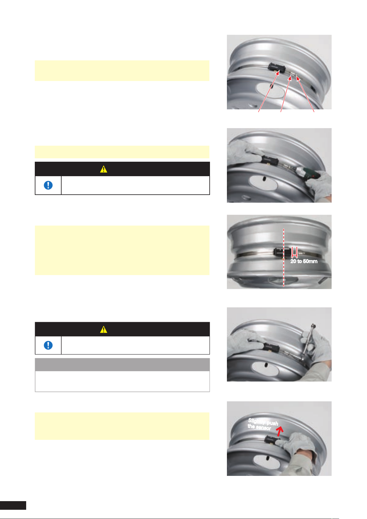
Insert the end of the mounting band through the band fastener so
2.
that the screw of the band fastener faces away from the sensor and
insert the screw.
• Check that the
mark on top of the sensor is facing the valve
side.
Attach a flat bit to the power driver and tighten the screw until there
3.
is no sag in the mounting band.
•
The screw should be loose enough to move the sensor.
WARNING
•
Be sure to read the operation guide before using the
power driver. Otherwise, you may hurt yourself.
Adjust the sensor position.
4.
• Adjust the position so that the center of the sensor is aligned with
the position of the valve.
• Adjust so that the distance between the mounting band fastener
and sensor is between 20 to 50 mm.
• Check that the mounting band is straight and in the center of the
rim well.
mark
Fastener
Fastener screw
20 to 50mm
Tighten the screw with torque wrench.
5.
Torque: 5 N·m
WARNING
• Tighten with prescribed torque so that the mounting
band does come loose during driving.
NOTE
The fastener or screw may become deformed and damaged if the
•
torque is greater than the prescribed value.
Check that the sensor is not loose.
6.
• Gently push the sensor away (with force about 1 kg) and check
that it is not displaced. If the sensor is displaced, loosen the
mounting band once and repeat the procedure from step (4).
Center of sensor aligned with position of valve
Torque: 5N·m
Slightly push
the sensor
Check that the installed sensor is not loose
12
Page 15
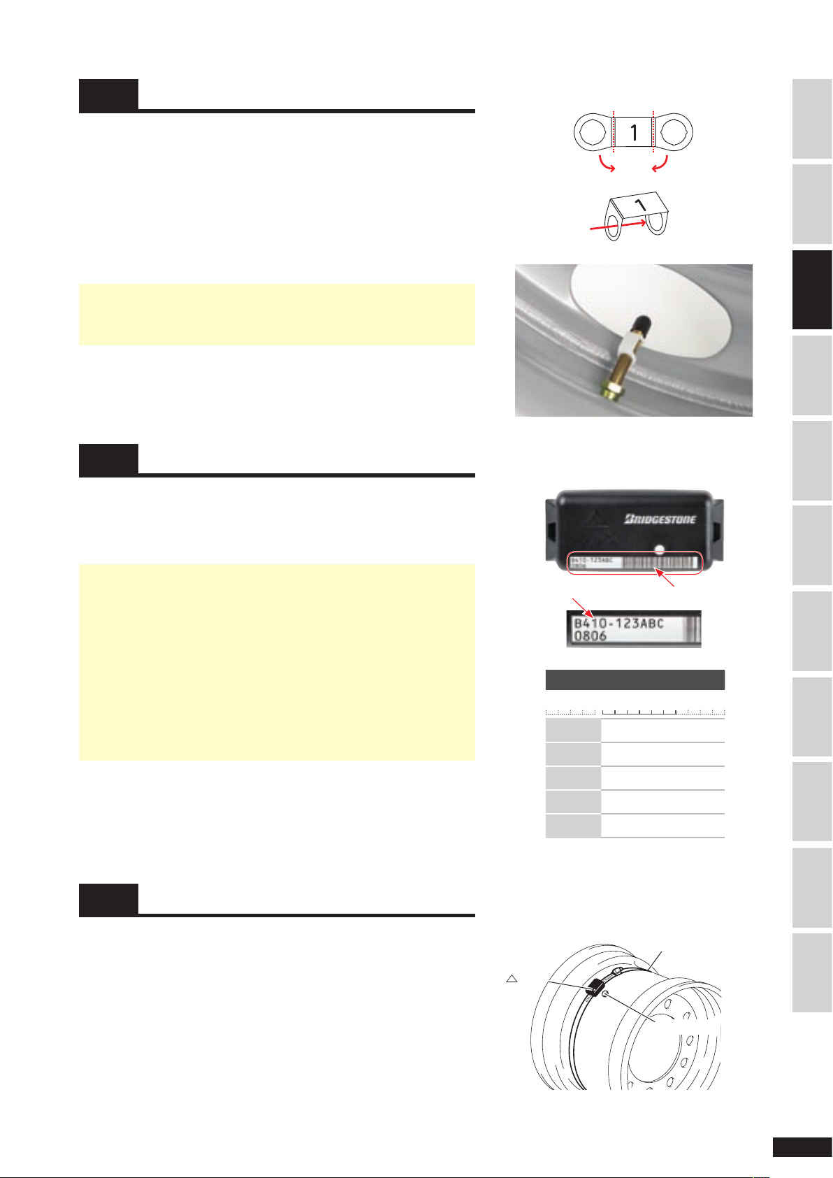
1-7 Attach the valve mark
Bend
Pass valve
through
Bend
mark
Va
lve hole
Outer side
Mounting band
Ve
hicle
side
Attach a valve mark on the valve of the rim with sensor installed so
that you can easily determine which tire (rim) has the sensor installed.
Bend both ends of the valve mark.
1.
Remove the valve cap and pass the valve through both holes of the
2.
valve mark.
Attach the valve cap.
3.
• The number on the valve mark indicates the installed position of
tire. Attach a valve mark with number matching the installed
position of tire.
1-8 Enter in check sheet
Enter the serial no. (S/N) of the installed sensor in the Check Sheet at
the end of this manual to record which tire (rim) has the sensor
installed (S/N is indicated on the barcode label on the surface of the
sensor).
• The sensor ID is the six digit alphanumeric string at the center of
the sensor.
This is the six digit string displayed on the LED panel when the
data is read with hand reader.
• The check sheet is necessary when requesting sensor repair. Be
sure to enter the necessary data when installing the sensor.
• The barcode label will be hidden and the serial cannot be read
after mounting tire on rim.
Enter the sensor serial no. in the check sheet before mounting
tire on rim. Be sure to enter in the field matching the installed
position of tire.
Sensor serial number
Sen s or ser ial No .
B
4 1 0-1 2 3 A B C
Tire size
Pattern
Prescribed
pressure
Inflation
pressure
Rim
Attaching valve mark
Barcode label
1
kPa
kPa
×
Steel
Aluminum
SAFETY PRECAUTIONS INTRODUCTIONMOUNTING TIRE ON RIMREMOVE THE SENSOR
TRANSPORTATION,
STORAGE & DISPOSAL
TROUBLESHOOTINGSERVICE & REPAIRSPECIFICATIONINDEXSENSOR WARRANTY SENSOR INSTALLATION
1-9 For super single tire
The procedure to install the sensor on the super single tire rim is as
follows:
• Stand on the side that is to be the side of the vehicle when the tire
is mounted.
• Install the sensor next to the valve hole so that it is on the outer side
when the rim is mounted on the vehicle.
• Install so that the
hole.
• The remaining steps are the same as those in "1-6 Install the sensor"
(page 11).
mark of the sensor is facing toward the valve
This sensor's ID is "123ABC".
13
Page 16
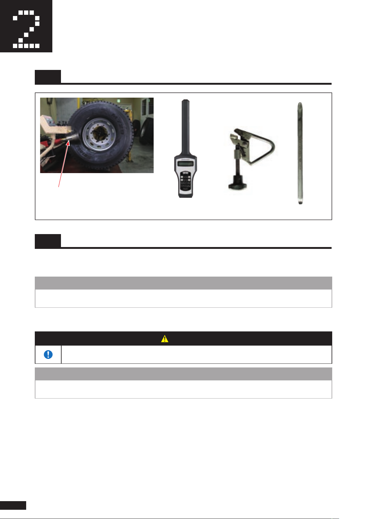
Mounting tire on rim and
Operation Verifi cation
2-1 Required tools
Tire changer
Bead roller
(Equipment used for mounting tire on rim. Generally
known as bead roller, bead breaker, or tire installer/
remover.)
Hand reader Clamp
Tire lever
2-2 Mounting tire on rim
Before mounting tire on rim, check that there is no moisture or foreign object inside the tire or rim. Remove all
1.
moisture and foreign objects if there are any.
NOTE
• Remove all moisture and foreign objects inside the tire if there are any. The sensor may be damaged and
performance may be degraded if moisture or foreign object enters the sensor.
2. After installing the sensor, apply lubricant to rim and tire beads.
WARNING
• Read the description of the lubricant carefully and use recommended lubricant.
Some lubricant may be fl ammable or harmful if inhaled.
NOTE
• Be careful not to apply lubricant to the sensor. If it is applied to the sensor, wipe it off immediately. The sensor may
be damaged and performance may be degraded if lubricant enters the sensor.
14
Page 17
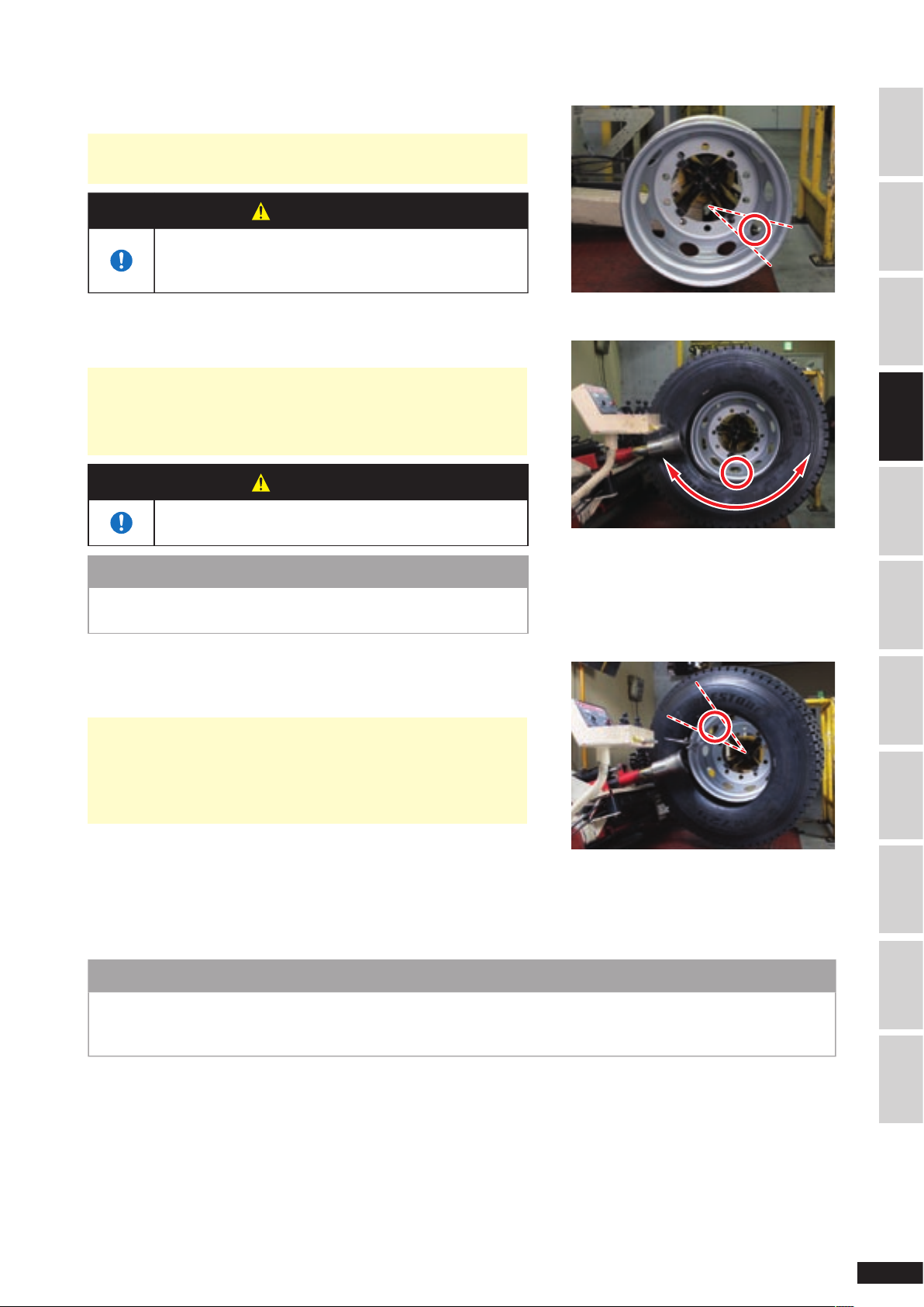
Set the rim on the tire changer.
3.
• Set so that the valve is lower than the horizontal position of the
bead roller (4 or 5 o'clock position).
WARNING
• Read the operation guide of the tire changer before
using. Failing to observe the warnings in the manual
may result in severe damage.
Push the bead roller and rotate the tire to insert the inner bead.
4.
• In order to prevent sensor damage due to contact with the tire
bead, rotate the tire so that the valve is lower than the horizontal
position of the bead roller (within the range of the arrow in figure)
when rotating the rim.
WARNING
• Be careful not to have your finger caught between the
tire bead and rim.
NOTE
• Be careful not to touch the tire bead to the sensor. If touched, the
sensor, band, or band fastener may be damaged.
Insert the outer bead.
5.
Hold the tire with a clamp or tire lever before rotating so that the
relative angle between the tire and rim do not change.
• Check that the relative position between the clamp or tire lever
and valve is as show in the figure.
• Hold the section where the tire enters the rim with tire lever so
that the tire fits the rim at the position of the lever and the tire
bead is kept from dropping on the sensor and damaging it.
Valve is between 4 to 5 o'clock position.
Valve is below the bead roller horizontal position
SAFETY PRECAUTIONS INTRODUCTIONSENSOR INSTALLATIONREMOVE THE SENSOR
TRANSPORTATION,
STORAGE & DISPOSAL
TROUBLESHOOTINGSERVICE & REPAIRSPECIFICATIONINDEXSENSOR WARRANTY MOUNTING TIRE ON RIM
With the bead roller pressed against the tire, rotate the rim until the
position of the valve is above the bead roller (10 to 11 o'clock
Valve is above the bead roller horizontal position
position).
Hold this position and rim the tire by rotating the rim, while taking care the tire and rim do not slip.
6.
NOTE
• Be careful not to touch the tire lever to the sensor. If touched, the sensor may be damaged.
• If the tire and rim slip, rotate the rim back to the original position and repeat the step.
If you continue, the tire bead and sensor may touch and damage the sensor.
(10 to 11 o'clock position)
15
Page 18
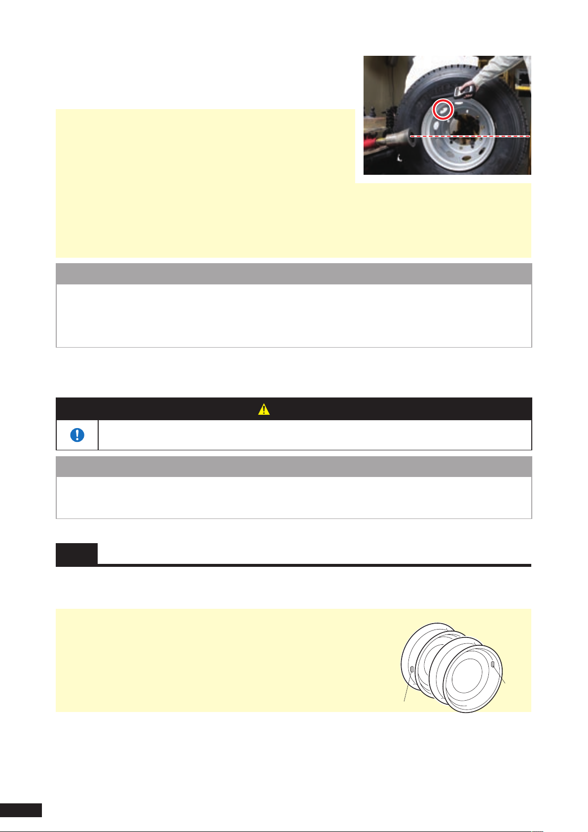
Sensor
Sensor
Check that the sensor is installed and operating correctly.
7.
Rotate the rim so t hat the positio n o f the valve is a bove t he
horizontal position of the bead roller and read the data with the
reader.
• Check that the sensor ID match the ID displayed on the hand reader
LED panel. Refer to section "1-8 Enter in check sheet" (page 13) for
information on sensor ID.
• To check that the sensor is not damaged or removed from the
mounting band during mounting tire on rim, hold the antenna of the
hand reader near the valve and check that the data can be read.
Refer to the hand reader operation guide for information on how to use the hand reader.
• If the data cannot be read, check whether it can be read near the bottom of the tire.
If it can be read at the bottom of the tire, the sensor may be damaged and dropped to the bottom of the tire. In this
case, de-rim the tire once and install the sensor once more. Refer to section "3-3 Remove the rim"(page 18) for the
de-mounting tire on rim procedure.
hand
NOTE
• Do not set the operation mode of the Hand Reader type to [Set]. Using the set mode may shorten the life of the
sensor considerably.
In this case, the sensor warranty will be voided.
• Refer to the description in the "On-Board Type Operation Guide" when checking the operation of the On-Board type.
Inflate the tire.
8.
After inflating, use soap water to check that no air is leaking from the valve or rim.
WARNING
• Be sure to inflate the tire inside a safety enclosure.
If the tire is improperly rimmed, the tire can burst and fly apart causing serious injury.
NOTE
• Be sure to drain the tire. The sensor may be damaged and performance may be degraded if moisture enters the
sensor.
• Be careful not to tip the tire and damage the sensor when carrying the tire to the safety enclosure.
2-3 Install the tire on the axle
Install the tire on the axle.
1.
After checking for proper operation, install the inflated tire on the axle.
• In case of double tire, be sure to offset the position of the valve of the inner
tire and outer tire by 180°.
If the positions of the inner and outer tire valve are not offset, data may not
be read correctly due to radio interference.
Enter the necessary data in the check sheet.
2.
Enter the necessary data in the check sheet at the end of this manual to keep record of the sensor installation.
Check that the installed position of tire entered in section "1-8 Enter in check sheet" (page 13) is the same as the actual
position.
16
Page 19
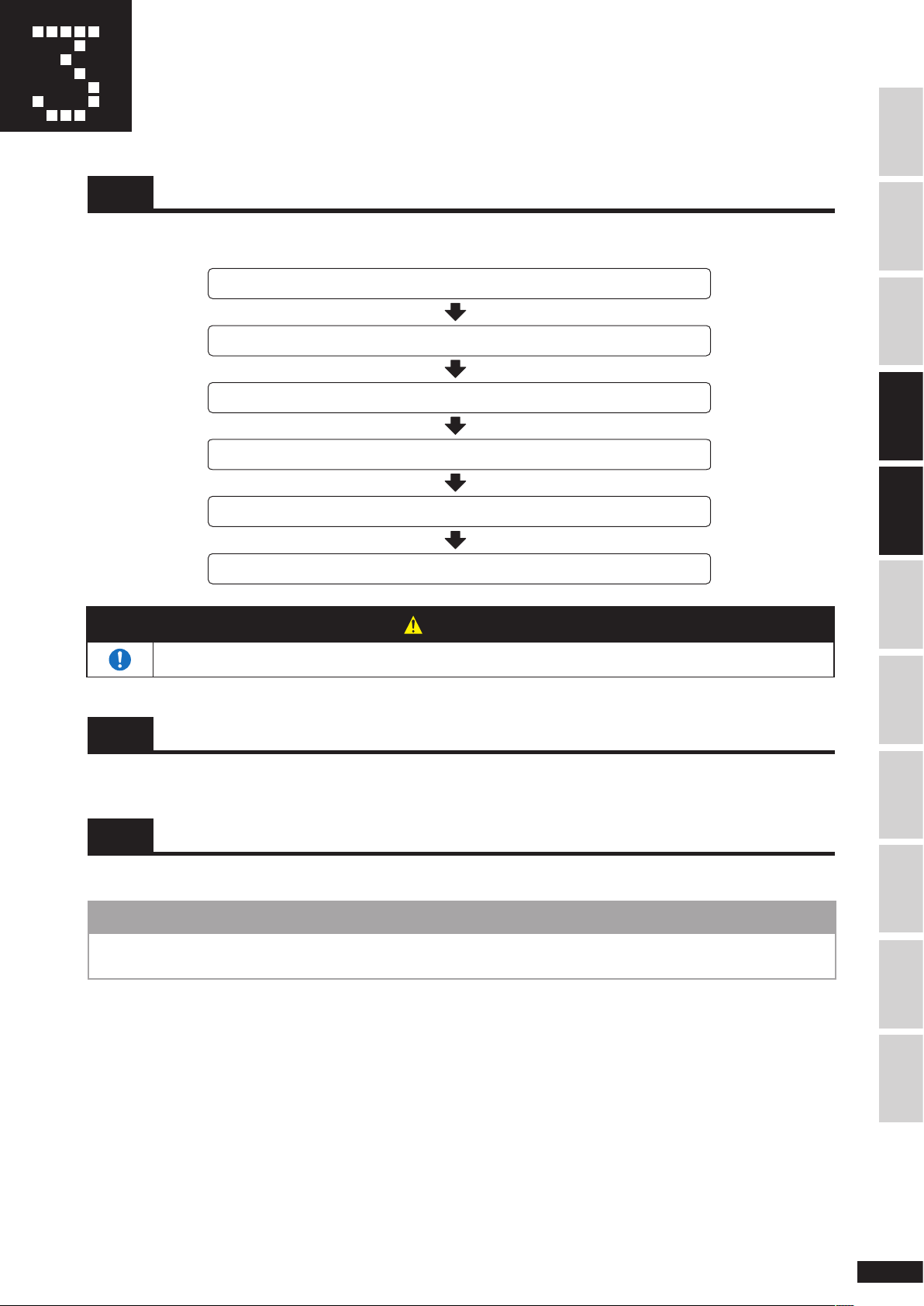
Remove the Sensor
Jack up the vehicle
Remove the tire from the axle
Remove the rim
Remove the sensor from the rim
Rim the tire
Install the tire on the axle
3-1 Sensor removal flow
Remove the sensor from the rim in the following order:
SAFETY PRECAUTIONS INTRODUCTIONSENSOR INSTALLATION
WARNING
• Install or uninstall the sensor at a tire shop.
3-2 Required tools
Use the same tools as those used for mounting tire on rim.
3-3 Remove the rim
Deflate the tire.
1.
NOTE
• Be careful not to tip the tire and damage the sensor when carrying the assembled tire to the tire changer after
deflating.
TRANSPORTATION,
STORAGE & DISPOSAL
TROUBLESHOOTINGSERVICE & REPAIRSPECIFICATIONINDEXSENSOR WARRANTY MOUNTING TIRE ON RIMREMOVE THE SENSOR
17
Page 20
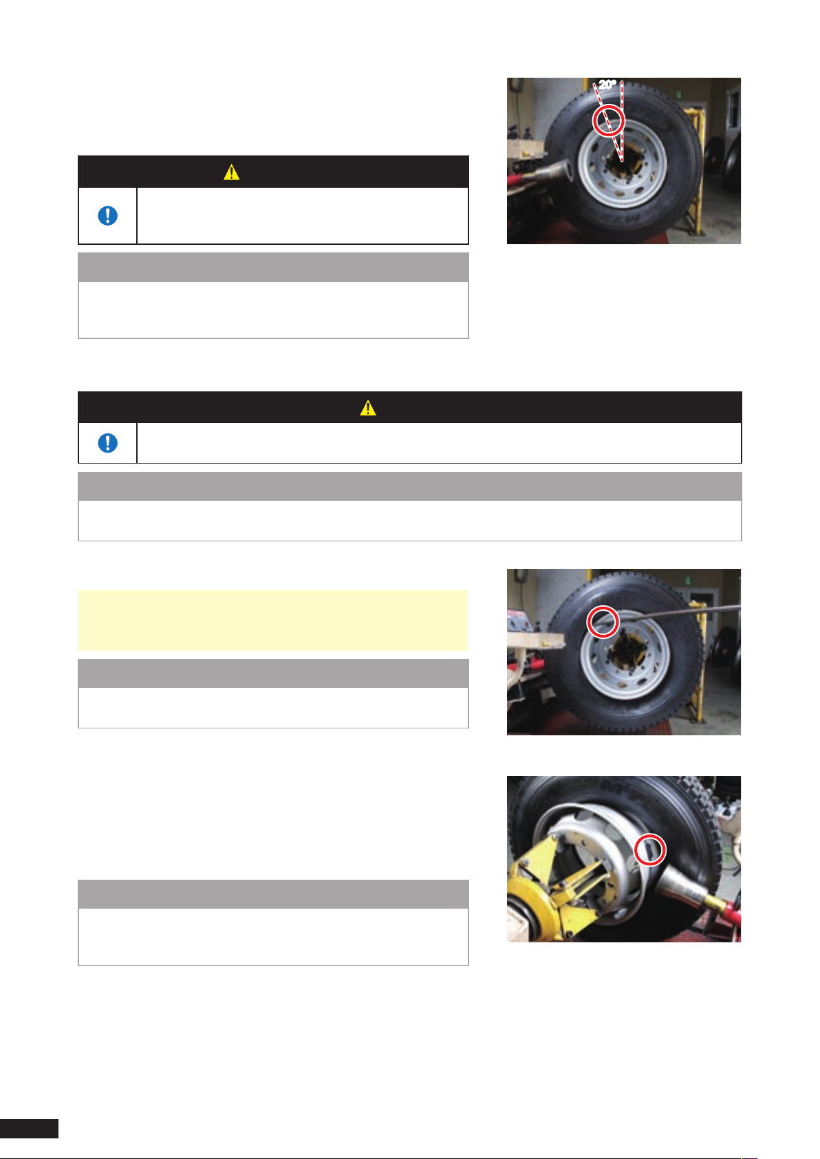
Place the tire on the tire changer.
2.
Set the rim so that the valve is approximately 20° from the top of the
tire.
(The sensor is in the rim well near the valve.)
WARNING
• Read the operation manual of the tire changer before
using. Failing to observe the warnings in the manual
may result in severe damage.
20°
NOTE
• If the rim well is shallow, the sensor may touch the tire bead and
become damaged when removing the rim. Be especially careful
when removing.
Apply lubricant to the flange.
3.
Set the rim so that the valve is approximately
20° from the top of the tire
WARNING
• Read the description of the lubricant carefully and use recommended lubricant.
Some lubricant may be flammable or harmful if inhaled.
NOTE
• Be careful not to apply lubricant to the sensor. If it is applied to the sensor, wipe it off immediately.
The sensor may be damaged and performance may be degraded if lubricant enters the sensor.
Insert the tire lever and pull out the outer bead.
4.
• Normally, no tire lever is used when de-mounting tire on rim with
tire changer, but it is used in this case to prevent the tire and rim
from slipping and damaging the sensor.
NOTE
• Be careful not to touch the tire lever to the sensor. If touched, the
sensor may be damaged.
Remove the outer bead.
5.
After pulling out the outer bead in step (4), rotate the tire with the
tire lever attached to the position in the figure, push the inner bead
with bead roller, and remove the outer bead.
Move the inner bead aside from the sensor to the position in the
figure to prevent damage to the sensor.
NOTE
• Set the distance between the bead roller and rim flange to a
minimum so that the bead roller does not touch the sensor. If
touched, the sensor may be damaged.
Pull out the outer bead with tire lever
Move the inner bead aside to position
where it does not hit the sensor
18
Page 21
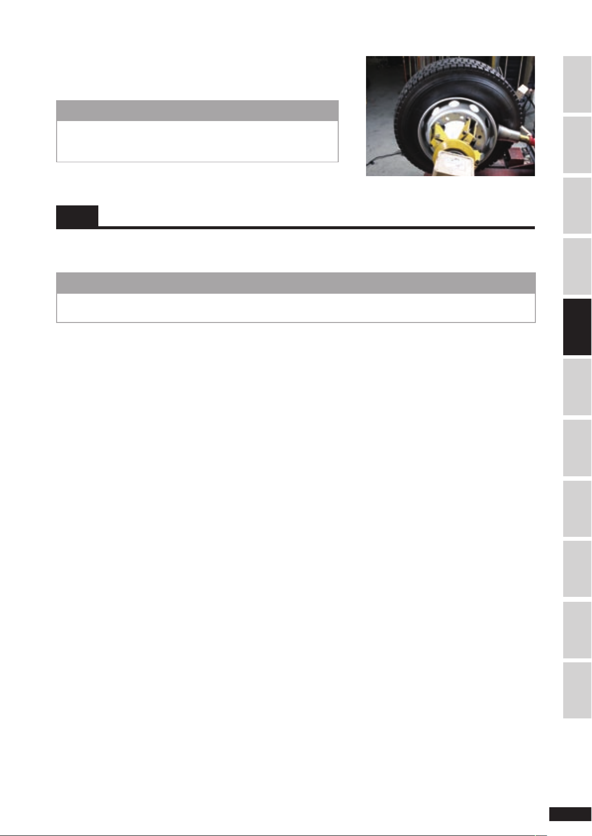
Remove the inner bead.
6.
With the outer bead removed in step (5), push the inner bead with
the bead roller and remove the inner bead from the rim.
NOTE
• If the tire bead is caught in the sensor, change the alignment of
the sensor and the bead roller without moving the bead roller in
order to prevent damage to the sensor and then resume.
Remove the inner bead
3-4 Remove the sensor from the rim
To remove the sensor from the rim, reverse the procedure in "1 Sensor Installation" (page 8).
When removing the sensor, be sure to remove the valve mark from the valve and store it together with the sensor.
NOTE
• The mounting band cannot be reused once it has been used. Re-using a mounting band can cause the sensor or
band to drop out when driving the vehicle, resulting in rim or tire damage.
SAFETY PRECAUTIONS INTRODUCTIONSENSOR INSTALLATIONMOUNTING TIRE ON RIM
TRANSPORTATION,
STORAGE & DISPOSAL
TROUBLESHOOTINGSERVICE & REPAIRSPECIFICATIONINDEXSENSOR WARRANTY REMOVE THE SENSOR
19
Page 22

Sensor Transportation,
Storage, and Disposal
The sensor periodically transmits radio waves (periodic transmission function). Therefore, you must stop the periodic
radio wave transmission function when transporting, storing, or disposing the sensor.
4-1 Precaution during transportation
Sensor used as Hand Reader type
Sensor used as Hand Reader type will not transmit radio signals unless instructed by the hand reader. It has no
periodic transmission function so it can be transported without any problem.
Sensor used as On-Board type
Sensor used as On-Board type is set to "Normal transmission mode" and periodically outputs radio waves.
When transporting sensor by air
Stop the periodic transmission using a separately purchased hand reader so that the radio waves from the sensor do
not interfere with the electronic equipment on the airplane. Refer to the "On-Board Type Operation Guide" for
information on how to set with the hand reader.
4-2 Precaution during storage
Both the Hand Reader type and On-Board type sensor must be placed in a sealed metal box when storing to shield them
from hand reader signals and 125 kHz frequency radio signals (output by some types of inverter, IC card reader, or ID
card reader).
NOTE
• When storing for an extended period, stop the periodic transmission of sensor used as On-Board type.
4-3 Precaution during disposal
Your purchasing dealer will salvage the sensor you no longer need. Contact your dealer when disposing the sensor.
20
Page 23
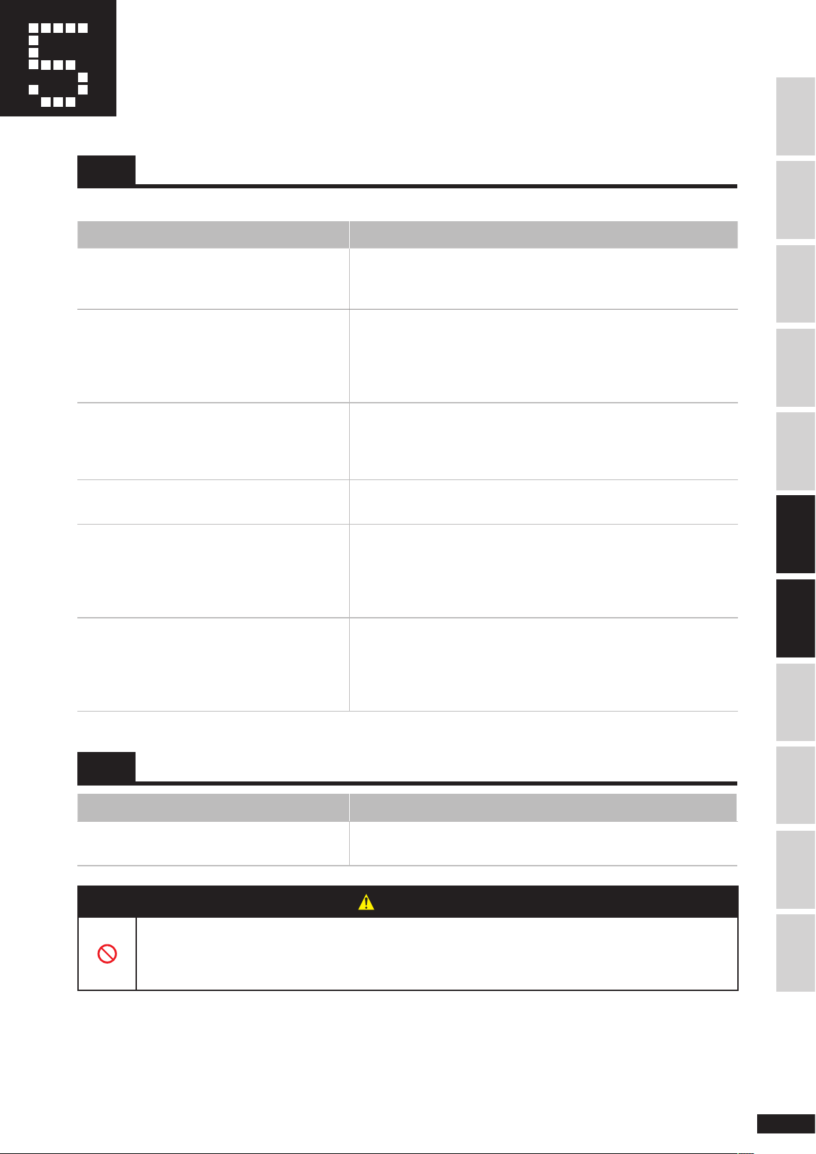
Troubleshooting
5-1 No response from the sensor
The possible causes are as follows.
Cause Remedial Action
SAFETY PRECAUTIONS INTRODUCTIONSENSOR INSTALLATIONMOUNTING TIRE ON RIMREMOVE THE SENSORSERVICE & REPAIRSPECIFICATIONINDEXSENSOR WARRANTY
You may be measuring a tire with no sensor
installed or with other manufacturer's sensor
installed.
The sensor has become loose inside the tire
and has dropped to the bottom of the tire.
The mounting band was not sufficiently
tightened during installation and the sensor has
moved from the position of the valve.
The sensor was damaged when mounting tire
on rim.
The hand reader is damaged or is not used
properly.
The sensor battery has expired.
Check the presence of valve mark and the check sheet to determine
whether a sensor is installed.
Position the tire so that the valve is on the top side and measure by
positioning the hand reader antenna at the bottom of the tire.
If there is response at the bottom of the tire, the sensor may have
become loose and dropped. Remove the rim and check the sensor. If
the sensor is damaged, replace it with a new one.
Position the hand reader antenna at several spots around the tire and
measure.
If there is a response at position not near the valve, remove the rim
and tighten the mounting band once more.
Remove the rim and check the sensor.
If the sensor is damaged, replace it with a new one.
• Check the measurement procedure once more and check whether
measurement cannot be obtained with any tire.
• The battery of the hand reader may be low. Replace it with a new
one.
If still there is no response, ask the dealer where you purchased it.
If other sensors respond but a specific sensor does not, remove the
ri m, place the ha nd reader an te nn a directly ag ai ns t the nonresponding sensor and measure.
If there is no response, the sensor may be damaged. Replace it with
a new one.
TRANSPORTATION,
STORAGE & DISPOSAL
TROUBLESHOOTING
5-2 When the sensor is damaged
Symptom Remedial Action
Sensor is damaged
• Do not disassemble, modify, or repair the sensor. This can cause sensor dropout, battery heating or
ignition.
• If the problem cannot be solved after taking the remedial action described in this guide, contact your
place of purchase.
The mechanical strength may be insufficient even if there is response
when measured with hand reader. Replace it with new one.
WARNING
21
Page 24
Service and Repair
If there is any problem during usage, stop using the sensor immediately.
WARNING
• If the problem cannot be solved after taking the remedial action described in this guide, contact your
place of purchase.
6-1 Requesting repair
When requesting repair, you may be asked for the content of the check sheet during installation and for the following
information. Check the necessary information.
Hand reader type
Symptom
C i r c u m s t a n c e u n d e r which th e
problem occurred
Sensor usage start date mark
L a s t da t e / t i m e the s e n s o r wa s
operating normally
Date/time you noticed the sensor
problem
Current odometer reading
On-board type
Sensor usage start date mark
Date and time of the problem
Frequency of the problem
No response / Wrong measurement / Others (select one)
Date (mm/dd):
Date (mm/dd/yyyy):
Date (mm/dd/yyyy):
km
Date (mm/dd):
Date (mm/dd/yyyy):
Morning / Daytime / Evening / Night
Daily / Several times a day / Once a week / Only after starting the engine/
Only once (select one)
Vehicle condition under which the
problem occurred
Character displayed on the display
panel
Color of the tire position lamp at time
of the problem and whether it was
ON, blinking or OFF.
Has the vehicle been repaired recently
or was any electronic equipment or
wireless equipment installed?
22
Moving/Stopped (select one) If moving, speed km/h
Tire position lamp: 1 / 2 / 3 / 4 / 5 / 6 / 7 / 8 / 9 / 10 / 11 / 12
Tire position lamp color: Red / Yellow / Green
Tire position lamp status: ON / Blinking / OFF (select one)
Vehicle repair Yes / No (select one)
Electronic or wireless equipment installed Yes / No (select one)
Page 25
WARNING
Failure to observe the following warning items may result in serious traffic accident due to tire damage or
erroneous air pressure detection.
• If there is any problem during usage, stop using the sensor immediately.
• Do not leave damaged sensor inside the tire for an extended period.
6-2 Routine Maintenance
Correct operation and routine maintenance are necessary to use this product safely.
Be sure to measure the tire pressure with a normal pressure gauge during routine maintenance. Compare those results
with the tire pressure displayed by this system and check that the system is functioning properly.
6-3 Disposal of the product
Your purchasing dealer will salvage the sensor you no longer need. When disposing the sensor, please take it back to the
place where you purchased it.
SAFETY PRECAUTIONS INTRODUCTIONSENSOR INSTALLATIONMOUNTING TIRE ON RIMREMOVE THE SENSOR
6-4 Contact
This product has been manufactured with utmost care, but please contact your purchasing dealer if there is any problem.
TRANSPORTATION,
STORAGE & DISPOSAL
TROUBLESHOOTINGSPECIFICATIONINDEXSENSOR WARRANTY SERVICE & REPAIR
23
Page 26

Specification
Product Specification
Pressure measuring range 0 to 1170 kPa
Pressure measuring precision ±30 kPa (500 to 900 kPa, -20 to +100°C)
Temperature measuring range -40 to +125°C
Transmitting frequency B421:300 MHz, B422:433MHz
Sensor
The specifications may change without prior notice for product improvement.
Compliance to radio wave law
Weight (excluding mounting band)
Environment condition Storage temperature: -40 to +125°C
B421: FCC/IC, B421:R&TTE
30g
Operating temperature: -40 to +125°C
Others: No condensation
24
Page 27

Index
Symbol
mark ........................................................ 8, 10, 11, 12
△
Alphabet
A
Antenna ................................................................ 15, 20
Applicable radio law ....................................................
B
Band fastened sensor ...................................................
Barcode label ..........................................................
Battery life ....................................................................
Bead roller ............................................
C
Check sheet ..........................................................
Clamp ................................................................... 13, 14
D
Display ................................................................
Disposal ................................................................ 19, 21
Double tire .................................................................. 15
E
ECU .................................................................... 2, 3, 28
Environment condition ................................................
F
Fastener ...........................................................
Frequency ...................................................................
14, 15, 16, 17, 18
23
8
8, 12
5
12, 21
2, 3, 28
23
10, 11, 12
23
O
On-board type .........................................
P
Periodic maintenance .............................................
Pressure measuring precision ....................................
Pressure measuring range ..........................................
R
Receiver ....................................................................
Remove the rim ........................................
Rim size ......................................................
Rim well .............................................................
S
Serial ........................................................................... 12
Socket size ....................................................................
Storage ............................................................ Cover, 19
Super single tire .......................................................... 12
T
Temperature measuring range ....................................
Tightening torque ....................................................... 12
Tire changer ...........................................
Tire installer/remover ..................................................
Tire lever ...........................................
Torque ..........................................................................
Torque wrench .........................................................
Transmitting frequency ...............................................
Transportation ............................................................. 19
2, 3, 15, 19, 21
3, 22
23
23
2, 3
3, 6, 15, 16,17
1, 5, 6, 9, 10
9, 10, 11
9
23
6, 13, 14, 16, 17
13
6, 13, 14, 15, 17, 18
11
9, 11
23
SAFETY PRECAUTIONS INTRODUCTIONSENSOR INSTALLATIONMOUNTING TIRE ON RIMREMOVE THE SENSOR
TRANSPORTATION,
STORAGE & DISPOSAL
TROUBLESHOOTINGSERVICE & REPAIRSENSOR WARRANTY SPECIFICATIONINDEX
H
Hand reader ............................. 1, 2, 3, 12, 13, 15, 19, 20
I
ID .......................................................................... 12, 15
Inflate ................................................................ 6, 15, 16
L
Lubricant ................................................................ 13, 17
M
Mounting band ............... 1, 6, 8, 9, 10, 11, 12, 17, 18, 20
Mounting tire on rim .............................. 3, 12, 13, 15, 20
U
Usage start date mark ........................................
V
Valve hole ...................................................................
Valve mark ..........................................
W
Warning lamp .....................................................
Weight ........................................................................
1, 6, 9, 12, 18, 20
8, 9, 21
2, 3, 28
12
23
25
Page 28

Sensor Warranty
1. The warranty period of this product is one year from the date of purchase.
2. Bridgestone shall replace the product without charge if it fails within the warranty period under normal usage as
described in the operation guide. To request replacement, please bring the product together with proof of purchase
date (receipt) to the place of purchase. However, the warranty shall be voided in the following cases:
(1) If you have no proof of purchase date
(2) Malfunction caused by ignoring the methods and cautions described in the operation guide
(3) Malfunction caused by dropping, compressing, or submersing in water
(4) Malfunction caused by modification or repair by unauthorized person or dealer
(5) Malfunction caused by improper storage
(6) Malfunction caused under extreme condition
(significant accumulation of dust, dirt, moisture or evidence of such)
(7) Malfunction caused by reasons scientifically and technically unforeseeable at the time the product was shipped
(8) Malfunction caused by accidents such as fire, earthquake, flood
3. The scope of the warranty is limited to replacement of the product itself and excludes compensation of any incidental
damages (loss of profit, data, etc.) that may have resulted from the malfunction of the product.
4. This warranty guarantees replacement of the product without charge within the period and under the conditions
described herein. Therefore, it is not intended to limit the legal rights of the customer.
5. Bridgestone shall assume ownership of the replaced failing product regardless of whether it is free of charge or not.
6. This warranty is valid only when the product is used in Europe and USA.
(This warranty is valid only in Europe and USA)
Bridgestone Corporation Customer Service
Toll free number 0120-39-2936
Hours: Monday to Friday (except holidays)
9:00 to 12:00 and 13:00 to 17:00
26
Page 29

memo
SAFETY PRECAUTIONS INTRODUCTIONSENSOR INSTALLATIONMOUNTING TIRE ON RIMREMOVE THE SENSOR
TRANSPORTATION,
STORAGE & DISPOSAL
TROUBLESHOOTINGSERVICE & REPAIRSPECIFICATIONINDEXSENSOR WARRANTY
27
Page 30
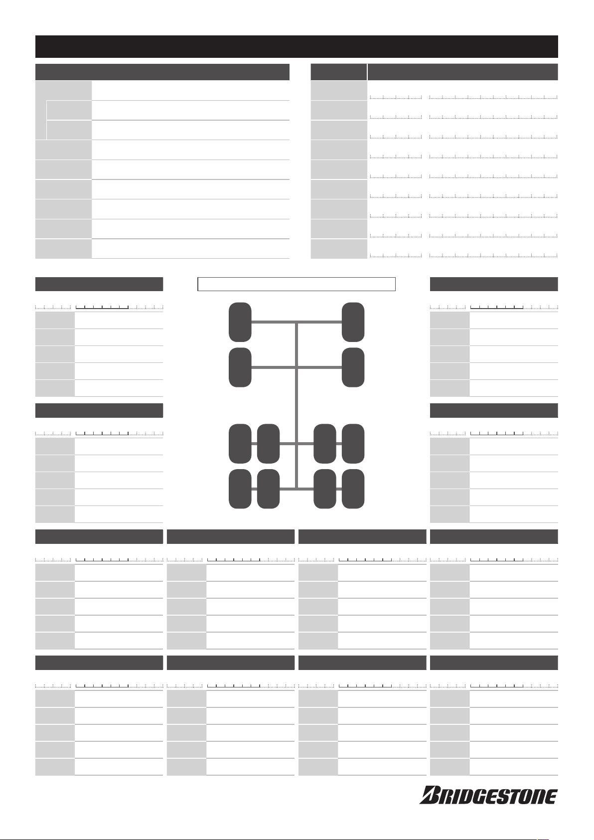
T i r e - P r e s s u re Mo n i to ri n g Sy s t e m Ch e c k S h e e t
* C o p y an d u s e
Installation
date
Start time
End time
Vehicle no.
Wheel
arrangement
Mileage
Model/Make
Vehicle type
Installing
person
Sen s or ser ial No .
Date (mm/dd/yyyy):
Date (mm/dd/yyyy):
Date (mm/dd/yyyy):
2-D / 2- D·2 / 2· 2-D / 2- D·4 / 2- D·D / 2· 2-D · D
B -
Tire size
Pattern
Prescribed
pressure
Inflation
pressure
Rim
×
Sensor Installation Status
:
:
km
1
kPa
kPa
Steel
Aluminum
Part name Serial No.
( Day)
PAM
PAM
M
M
Warning lamp
Display
ECU
Receiver 1
Receiver 2
Receiver 3
Receiver 4
Receiver 5
Receiver 6
Enter the serial no. in the above table for On-board type only.
Installed position of tire
21
3
4
W
D -
E -
R -
R -
R -
R -
R -
R -
-
Sen s or ser ial No .
B -
Tire size
Pattern
Prescribed
pressure
Inflation
pressure
Rim
2
kPa
kPa
×
Steel
Aluminum
Sen s or ser ial No .
B -
Tire size
Pattern
Prescribed
pressure
Inflation
pressure
Rim
Sen s or ser ial No .
×
B -
Tire size
Pattern
Prescribed
pressure
Inflation
pressure
Rim
Sen s or ser ial No .
×
B -
Tire size
3
kPa
kPa
Steel
Aluminum
5
kPa
kPa
Steel
Aluminum
9
5
9
Sen s or ser ial No .
B -
Tire size
Pattern
Prescribed
pressure
Inflation
pressure
Rim
Sen s or ser ial No .
B -
Tire size
×
6
Steel
Aluminum
Sen s or ser ial No .
6
B -
Tire size
Pattern
Prescribed
kPa
pressure
Inflation
kPa
pressure
Rim
Sen s or ser ial No .
1 0
B -
Tire size
Sen s or ser ial No .
4
B -
87
121110
Tire size
Pattern
Prescribed
pressure
Inflation
pressure
Rim
Sen s or ser ial No .
7
kPa
kPa
×
Steel
Aluminum
8
B -
Tire size
Pattern
Prescribed
kPa
pressure
Inflation
kPa
pressure
×
Steel
Aluminum
1 1
Rim
Sen s or ser ial No .
×
kPa
kPa
Steel
Aluminum
1 2
B -
Tire size
Pattern
Prescribed
pressure
Inflation
pressure
Rim
kPa
kPa
Pattern
Prescribed
pressure
Inflation
pressure
Rim
kPa
kPa
×
Steel
Aluminum
Pattern
Prescribed
kPa
pressure
Inflation
kPa
pressure
×
Steel
Aluminum
Rim
×
Steel
Aluminum
kPa
kPa
Pattern
Prescribed
pressure
Inflation
pressure
Rim
×
Steel
Aluminum
Page 31

Page 32

Manufacturing and Sales
Bridgestone Corporation
1-10-1 Kyobashi Chuoku Tokyo 104-8340
http://www.bridgestone.co.jp/
Apr. 2006
Base REG Developmen
Copyright © 2006 Bridgestone Corporation
2006.04 Base
t
Ⓐ
 Loading...