

Page 1
t
vv
N
£
iv,-
x
OPERATING
i
V
R2E3
MILLING,
0
$
V
V
DRILLING
FOR
SERIES
MANUAL
THE
;
\
I
&
SCJfiJNG
CNO
K
\»
MACHINE
*v
1
{.
K
s
*
.
*4
/;•
%ÿ
*
l
1
;
4
*
!
Page 2

m
m
tty
y
MILLING,
OPERATING
FOR
R2E3
DRILLING
SERIES
MAY,
MANUAL
x,
THE
I
BMJ!3C-
«
1983
GNC
V.
MACHINE
HrrdijefMtri
Bridgeport
TEXTRON
Machines
Division
Textron
of
Inc.
REV
11040531
0
5/83
Page 3
mm
SHH
1
1
m
iftV.
v
mm
'J
&
i
II
mm
m
M
r
mm
r'!-4
Pm
1
"
Machines
for
does
1983
the
BRIDGEPORT
provides
use
or
dissemination
is
in
this
not
of
Textron
ALL
Division
maintenance
and
prohibited.
document
constitute
COPYRIGHT
This
Bridgeport
available
reproduction,
written
m
The
notice
Machines
»*•
;s;::
V-
document
permission
information
and
Division
MACHINES
RIGHTS
information
of
Inc.
ii
RESERVED
is
Textron
of
of
subject
a
DIVISION
which
our
this
is
Inc.
products.
information
to
commitment
TEXTRON
OF
proprietary
change
by
and
INC.
is
Any
withou
withou
Bridgepor
t
mad
use
Ill
H.:-.
\
till
Page 4
Ill,
1
prevent
To
ing,
operating
These
and
entitled
Machines
publication
This
servicing
or
1.
2.
3.
4.
bodily
Follow
Wear
not
Do
other
Keep
serious
gears,
Use
5.
safety
other
Safety
(ANSIB11.8-1974).
Requirements
is
available
injury,
your
instructions
all
approved
wear
loose
all
proper
precautions
items
parts
etc.)
point
from:
SAFETY
you
should
Bridgeport
industrial
gloves,
that
your
of
of
are
for
the
The
1430
New
observe
milling
in
the
safety
long
sleeves,
could
body
operation
discussed
Construction,
American
Broadway
York,
New
INFORMATION
following
the
machine.
machine
glasses
long
from
the
Care,
caught
American
become
away
safeguarding.
in
National
York
10018
manual.
and
hair,
moving
Standards
and
basic
safety
rings,
in
National
Use
moving
parts
safety
shoes.
watches,
parts.
(belts,
Standards
of
Drilling,
Institute
precautions
jewelry
cutters,
Institute
Milling,
or
when
Standard
and
install¬
Boring
Safeguarding
parameters
states
guarding
To
tions,
Techniques
This
that
assist
the
publication
device,
machine
Occupational
for
of
the
shall
“it
Machine
of
protection
particular
be
the
awareness
users
is
in
Safety
Safeguarding
available
point
the
at
operation
responsibility
barrier,
designing
from:
and
awareness
Health
The
200
Washington,
of
have
point
(O.S.H.A.
Publication
Department
U.S.
Constitution
operation
been
determined.
of
of
Administration
employer
the
device,
operation
Publication
Office
of
Avenue,
D.C.
only
can
to
or
shield...".
safeguarding
published
has
Number
—
Labor
20210
be
designed
result,
a
As
provide,
3067).
O.S.H.A.
NW
for
and
their
a
booklet
and
ANSI
ensure
specific
constructed
1.8-1974,
B1
the
machine
entitled
Section
of,
use
Concepts
when
guard,
a
applica¬
the
5.1,
and
.
Page 5
TABLE
P
OF
CONTENTS
m
M
m
M
CHAPTER
1.1
1.2
1.3
1.4
1.4.1
1.4.2
1.4.3
1.5
1.5.1
1.5.2
1.5.3
1.5.4
CHAPTER
2.1
2.1.1
2.2
2.2.1
2.2.2
2.2.3
2.2.4
2.2.5
2.2.6
2.3
2.3.1
2.3.2
2.4.
2.5
2.6
2.6.1
2.6.2
1
PURPOSE
REFERENCE
GENERAL
ARCHITECTURE
Milling
Control
ElectroMechanical
MODES
Set
Run
MDI
MDI
2
OPERATOR
Front
FRONT
Machine
SET
RUN
Special
MDI
Status
POWER
Spindle
Auxiliary
PORT
RESET
LUBE
Lube
Pneumatic
AND
DESCRIPTION
OF
OPERATION
Up
Mode
Mode
Mode
Store
CONTROLS
Panel
PANEL
UP
Manual
-
Indicators
&
CONTROL/AXIS
PORT
A/
SWITCH
&
PNEUMATIC
Assembly
INTRODUCTION
SCOPE
MANUALS
Machine
And
Power
(Manual
Mode
OPERATOR'S
Control
....
Controls
Operations
Data
Motor
Protection
Power
B
INTERFACE
Outlets
CONTROL
........
Assembly
Interface
Data
CONTROLS
.
Input
(LED)
DRIVE
Input)
AND
.
.
.
. . . .
. .
.
.
.
. . . .
SUBSYSTEM
SUBSYSTEM
INDICATORS
.
.
.
1-1
1-2
1-2
1-2
1-3
1-4
1-6
1-6
1-6
1-6
1-6
1-6
2-1
2-2
2-3
2-3
2-6
2-9
2-11
2-12
2-14
2-14
2-14
2-14
2-15
2-16
2-16
2-17
2-18
i
i
H
H
M
CHAPTER
3.1
3.1.1
3.1.2
3.2
3.2.1
3.2.2
3.2.3
3.3
3.4
3
START
Prestart
System
CONDITIONS
Default
Self
Self
NORMAL
EMERGENCY
UP
Test
Test
SHUTDOWN
SYSTEM
Considerations
Start
Condition
STOP
Up
FOLLOWING
Diagnostic
Error
START
Procedure
Messages
PROCEDURES
UP
START
Description
iii
/SHUTDOWN
.
.
. .
.
.
.
.
UP
. .
.
.
.
.
.
.
.
3-1
3-1
3-1
3-4
3-4
3-5
3-5
3-6
3-6
4
,f
w
L
Page 6
6.2.4
6.3
6.3.1
6.3.2
6.4
6.4.1
6.4.2
6.4.3
6.4.4
6.4.5
6.4.6
AUTO/
SPECIAL
The
DRY
SPECIAL
Travel
EMERGENCY
Spindle
Feed
Hold
Screen
BLOCK
OPERATIONS
OPTION
RUN
Key
CONDITIONS
Limit
Feed
Override
Error
Operation
Key
....
Switch
STOP
Hold
Messages
. .
. . .
. .
. . .
.
. .
6-4
6-4
6-4
6-5
6-7
6-7
6-7
6-7
6-8
6-8
6-8
CHAPTER
7.1
7.2
7.2.1
7.3
CHAPTER
8.1
8.2
8.3
8.4
8.5
8.5.1
8.6
8.7
CHAPTER
9.1
9.1.1
9.2
7
OVERVIEW
MDI
MODE
CANNED
STORE
MDI
8
OPTIONAL
PAPER
TAPE
EZ-FILE~
QUICK
#30
1-4
COOLANT
INDEXER
Physical
EZ-CAM~
9
TOOL
TOOL
HOLDERS
General
SETTING
OPERATION
CYCLE
OPTIONAL
EQUIPMENT
READER
MASS
CHANGE
Description
SYSTEM
TOOLS
....
Description
....
OPERATING
EQUIPMENT
STORAGE
TOOL
MIST
-
AND
IN
MDl/MDI
NOTES
DEVICE
KIT*
AND/OR
TOOL
HOLDERS
.
STORE
.
.
. .
FLOOD
MODE
7-1
7-1
7-2
7-10
8-1
.
8-1
.
.
8-1
,
8-2
8-2
8-3
8-3
8-3
9-1
9-1
9-2
APPENDIX
1
A.
APPENDIX
.1
B
B.
2
.
3
B
.
4
B
.
5
B
A
SYSTEM
B
OVERVIEW
STANDARD
MACHINE
CONTROL
TOTAL
LEADING
SYSTEM
SYSTEM
ERROR
SYSTEM
FEATURES
FEATURES
DATA
STATUS/
MESSAGES
SPECIFICATIONS
OF
FEATURES
(SERIES
THE
I
R2E3)
V
ERROR
BRIDGEPORT
MESSAGES
R2E3
SERIES
A-l
B
1
—
I
B-l
B-2
B-4
B-5
Page 7
3.5
3.6
3.6.1
3.6.2
POWER
RESET
RESET
RESET
FAILURE
PROGRAM
Pushbutton
Key
. .
Switch
3-6
3-6
3-7
3-7
CHAPTER
4.1
4.2
4.3
4.4
4.4.
1
4.4.
2
4.4.3
4.4.4
4.5
4.5.1
4.5.2
4.5.3
4.6
4.7
4.7.1
4.7.2
4.8
4.9
CHAPTER
4
SYSTEMS
MACHINE
AXIS
ENTERING
SETTING
MOVE
LOADING
CLEARING
EDITING
5
JOG
Manual
TLO
Tool
Cutter
Reference
Part
Clearance
OPERATION
Baud
Input
OPERATION
OPERATION
COORDINATE
TOOL
Knee
Input
Diameters
Diameter
REFERENCE
Point
Program
Point
PART
Rate
From
DATA
.
EDITING
SYSTEM
DATA
Adjustment
Compensation
POINTS
Zero
PROGRAMS
Peripheral
IN
(SET
SET
UP
.
.
....
....
XYZ)
. .
Equipment
MODE
.
.
.
4-1
4-2
4-4
4-5
4-6
4-7
4-10
4-10
4-11
4-12
4-13
4-14
4-14
4-15
4-15
4-16
4-18
4-19
5.1
5.2
5.2.1
5.2.2
5.2.3
5.2.4
5.2.5
5.2.6
5.2.7
5.2.8
5.2.9
5.3
5.3.1
5.3.2
CHAPTER
6.1
6.2
6.2.1
6.2.2
6.2.3
PROGRAM
QUICK
AUX
FULL
Description
Editor
6
OVERVIEW
NORMAL
Pre-Start
Starting
EDIT
FIND
INSERT
DELETE
RECALL
INCR
POLAR
"0
-
(Minus
EDIT
Program
EDITING
9",
Sign)
METHOD
Commands
OPERATION
OPERATION
The
Run
METHODS
(Decimal)
.
.
.
. . .
.
. .
Spindle
.
. . .
. .
.
IN
.
.
RUN
MODE
5-1
5-1
5-2
5-3
5-4
5-4
5-4
5-4
5-4
5-5
5-5
5-5
5-5
5-5
6-1
.
6-1
6-2
6-2
6-3
iv
Page 8
6.2.4
6.3
6.3.1
6.3.2
6.4
6.4.1
6.4.2
6.4.3
6.4.4
6.4.5
6.4.6
AUTO/BLOCK
SPECIAL
The
DRY
SPECIAL
Travel
EMERGENCY
Spindle
Feed
Hold
Screen
OPERATIONS
OPTION
RUN
Key
CONDITIONS
Limit
Feed
Override
Error
Operation
Key
....
Switch
STOP
Hold
Messages
. .
.
.
. .
. . .
.
.
.
6-4
6-4
.
.
6-4
6-5
6-7
6-7
6-7
6-7
6-8
6-8
6-8
CHAPTER
7.1
7.2
7.2.1
7.3
CHAPTER
8.1
8.2
8.3
8.4
8.5
8.5.1
8.6
8.7
CHAPTER
9.1
9.1.1
9.2
7
OVERVIEW
MDI
MDI
OPTIONAL
1-4
MODE
CANNED
STORE
8
PAPER
#30
Physical
ILE~
QUICK
INDEXER
EZ-F
COOLANT
TAPE
EZ-CAM~
9
TOOL
TOOL
HOLDERS
General
SETTING
OPERATION
CYCLE
OPTIONAL
EQUIPMENT
READER
MASS
CHANGE
Description
SYSTEM
TOOLS
....
Description
....
OPERATING
EQUIPMENT
STORAGE
TOOL
MIST
-
AND
IN
MDl/MDI
NOTES
DEVICE
KIT’
AND/OR
TOOL
HOLDERS
.
STORE
. .
. .
FLOOD
MODE
7-1
7-1
7-2
7-10
8-1
8-1
.
.
8-1
,
8-2
8-2
8-3
8-3
8-3
9-1
9-1
9-2
APPENDIX
1
A.
APPENDIX
.
B
1
B.
2
.
3
B
.
B
4
.
5
B
A
SYSTEM
B
OVERVIEW
STANDARD
MACHINE
CONTROL
TOTAL
LEADING
SYSTEM
SYSTEM
ERROR
SYSTEM
FEATURES
FEATURES
DATA
STATUS/
MESSAGES
SPECIFICATIONS
OF
FEATURES
(SERIES
ERROR
THE
BRIDGEPORT
R2E3)
I
v
MESSAGES
R2E3
SERIES
A-l
B-l
I
B-l
B-2
B-4
B-5
Page 9

APPENDIX
C
CONNECTORS
APPENDIX
D
GLOSSARY
vi
\
Page 10
LIST
OF
ILLUSTRATIONS
FIGURE
1-1
1-2
2-1
2-2
2-3
2-4
2-5
2-6
2-7
2-8
2-9
4-1
4-2
4-3
4-4
5-1
9-1
9-2
The
R2E3
R2E3
Series
Operator's
Machine
Speed
Speed
SET
RUN
MDI
Tape
Lube
Set
UP
Mode
Mode
Reader
&
up
Machine
Preset
Plug
Quick
Tool
Tool
Connectors
and
Setting
System
Controls
Range
Dial
Mode
Keys
-
Pneumatic
Mode
Coordinate
TLO
Edit
Tool
Functional
-
I
Front
Control
Panel
R2E3
Controls
Application
Adapter/
Controls
Keys
Measurement
for
Controls
Holder
Drawing
Keys
Remote
System
Tape/Local
Front
Serial
Panel
Blocks
I/O
Interface
PAGE
1-3
1-5
2-2
2-3
2-4
2-5
2-7
2-9
2-11
2-15
2-17
4-2
4-3
4-9
4-16
5-2
9-1
9-3
TABLE
4-1
7-1
A-l
A-2
Reference
MDI
Error
&
Error
LIST
Points
MDI
Store
Message
Combinations
OF
Sets
TABLES
and
Mode
vii
Tracking
Hex
-
To
Registers
Binary
PAGE
4-12
7-3
A-
2
A-
3
Page 11
CHAPTER
INTRODUCTION
1
1.1
This
necessary
Machine.
Control
Software,
This
PURPOSE
manual
The
(CNC),
Series
manual
o
Operator
o
System
o
System
o
Editing
AND
provides
to
is
MDI
SCOPE
operate
R2E3
using
I).
divided
Start
Operating
SET
RUN
MDI
Capabilities
the
is
Controls,
UP
STORE
the
totally
BOSS
into
Up/
operator
Bridgeport
8
the
and
Shutdown
Modes
with
dedicated
(Bridgeport
I
following
Indicators
information
R2E3
Series
to
major
and
I
Computer
Operating
sections:
CNC
examples
Milling
Numeric
System
o
o
o
Optional
Tool
Appendix
Holders
System
System
Equipment
*
Status/Error
Specifications
Messages
1-1
/
Page 12

o
Glossary
1.2
Two
REFERENCE
other
1.
2.
1.3
The
operated
It
GENERAL
Bridgeport
provides
interpolation
large
A
scale
communication
conjunction
known
as
checking
codes:
Transmission.
End
manuals
R2E3
R2E3
via
3
integration)
Port
transmitted
<DC1>
MANUALS
exist
Installation
Programming
DESCRIPTION
R2E3
a
axis
.
with
B.
Start
Series
Front
linear
The
protocol
the
The
Read,
for
Panel
design
.
remote
protocol,
data
this
and
Manual
CNC
I
with
and
embedded
serial
for
<DC2>
product.
Maintenance
(11040532)
is
an
axis
2
makes
,EIA
errors
Device
a
Vertical
LCD
(liquid
switchable
extensive
in
interface
RS-491,
using
on,
Manual
BOSS
<DC3>
Milling
crystal
use
8
port,
includes
the
Stop
(11040529)
plane
VLSI
of
is
I
which
means
following
Read,
Machine
display).
circular
(very
used
will
ASCII
<E0T>
in
be
for
1.4
The
together
Each
make
contains
ARCHITECTURE
system
as
2.
3.
section
the
Milling
Control
Interface
all
1.
contains
electromechanical
machine
and
contains
one.
is
system
mechanical
all
the
three
individual
The
Machine
and
Power
(electromechanical)
specialized
function
electronic
interface
control.
sections,
(mechanical)
(electrical)
and
as
aspects
provides
sections
interacts
a
of
aspects
1-2
see
whole.
the
the
Figure
are:
with
machine
of
link
1-1,
the
The
and
the
between
all
other
milling
the
machine.
working
machine
controller
milling
the
two
to
The
Page 13
HVIILLING
MACHINE"!
AO
H
E
ASSEMBLY
CONTROL
AND
POWER
FRONT
PANEL
SUBSYSTEM
|
1.4.1
Figure
Milling
BASE
ASSEMBLY
LUBE
ANO
M
1ST
ASSEMBLIES
zrLJ
1-1:
Machine
(TLECTROMECHANICATI
,
[
I
TACHOMETERS
i<=>!
[
L'
The
R2E3
INTERFACE
MOTORS
ENCOOERS
SOLENOIOS
System
I
I
tc=>
I
n
Functional
-
L
CENTRAL
PROCESSING
SUBSYSTEM
MACHINE
CONTROL
SUBSYSTEM
POWER
SUBSYSTEM
J
Blocks
This
section
1.
2.
3.
contains
Head
the
structure.
mounted
Base
axis),
and
Y
Lube
and
assembly.
the
way
lubricant.
Assembly
quill
to
this
Assembly
knee,
axis
and
filter,
drive
Mist
These
distribution
(
see
Contains
-
(Z
axis),
The
support
Contains
-
and
Assemblies
the
Figure
Z
axis
their
motors
lubrication
components
of
1-2
the
the
drive
structure.
the
support
are
pressurized
1-3
)
:
mechanical
pneumatics
motor
saddle
mounted
Contains
pump
are
structure.
the
and
(Y
to
•>
the
and
starting
air,
components
and
spindle
axis)
this
air
the
mist
their
,
The
structure.
optional
points
coolant
support
motor
table
X
regulator
of
are
(X
axis
mist
for
and
Page 14

1.4.2
Control
And
Power
This
section
1.
2.
3.
4.
consists
Front
Panel,
up.
These
Input),
Front
Up
mode
Control
feedback
Power
distributed
parts
Controllers
voltage
Panel
in
Panel,
allowing
-
Incoming
-
by
and
and
All
is
this
of
Most
-
any
modes
MDI
however
operator
analyzed
to
subsystem.
current
(see
operator
one
of
are;
Store.
modification
electrical
the
These
to
Figure
four
Set
is
it
and
by
this
controller
convert
the
1-2):
control
modes
Up,
Editing
intended
to
electronic
subsystem.
power
electrical
DC
motors.
following
Run,
existing
and
through
is
MDI
is
for
input
is
(Manual
possible
use
part
conditioned
electromechanical
signals
system
in
programs.
plus
the
via
the
machine
Front
start
Data
the
Set
and
into
1-4
Page 15
w
4L
3
3
1
LV
=sfeCNC
£3
E
"wj
gft£
mi
&
•
3*
i,
s
f
"3’
IC33
.V.
V;
ET““
fp<.
;
f
••';••-
i
:?rV
/'ÿif.,1:
l'.
*•
"/$
.‘A?
"af
A
IF
*#
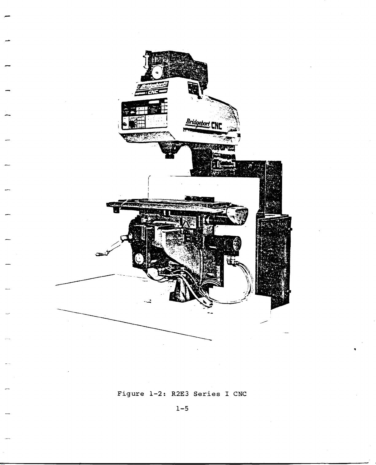
Figure
1-2:
R2E3
1-5
Series
I
CNC
Page 16
1.4.
3
ElectroMechanical
Interface
This
section
convert
1.
2.
3.
1.5
MODES
1.5.1
Set
Up
establishing
initial
electrical
DC
and
Encoders
from
can
Solenoids
pneumatic
OF
Up
Set
prepares
axis
contains
Motors
convert
the
decode.
OPERATION
Mode
the
machine
positions,
signals
and
motor
and
three
These
them
into
Tachometers
into
These
hydraulic
machine
reference
and
parts,
into
take
the
mechanical
drive
axis
electrical
convert
power.
for
points,
loading
Figure
see
current
movements.
These
electrical
part
of
motion.
convert
signals
making.
tool
part
1-2.
from
axis
which
characteristics,
programs.
This
These
the
movements
the
signals
parts
control
system
to
includes
1.5.2
Runs
either
work
1.5.3
In
block
1.5.4
The
part
the
this
MDI
end
Run
a
complete
with
MDI
mode
.
MDI
Store
program
of
in
Mode
Automatic
DNC
Mode
the
Store
the
LINK.
(Manual
mode
on
part
part
operator
Mode
allows
a
block-by-block
program
program
or
Block-by-Block
Data
can
the
Input)
input
operator
text
previously
and
basis,
buffer.
mode.
execute
to
and
loaded
input
Run
a
store
into
mode
single
and
each
memory,
will
program
execute
block
also
a
at
1-6
Page 17
CHAPTER
2
This
with
include
2.1
There
chapter
operator
the
OPERATOR
are
1.
2
3.
4.
four
Front
.
Power
Tape
Lube
OPERATOR'S
describes
controls
location
CONTROLS
groups
Panel
&
Control/Axis
Reader
and
the
and
of
Control
Adapter/
Pneumatic
CONTROLS
keys,
on
the
purpose
operator
Drive
Remote
Control
AND
knobs
milling
of
controls.
INDICATORS
and
each
Serial
machine.
control.
Interface
switches
associated
Descriptions
2-1
Page 18
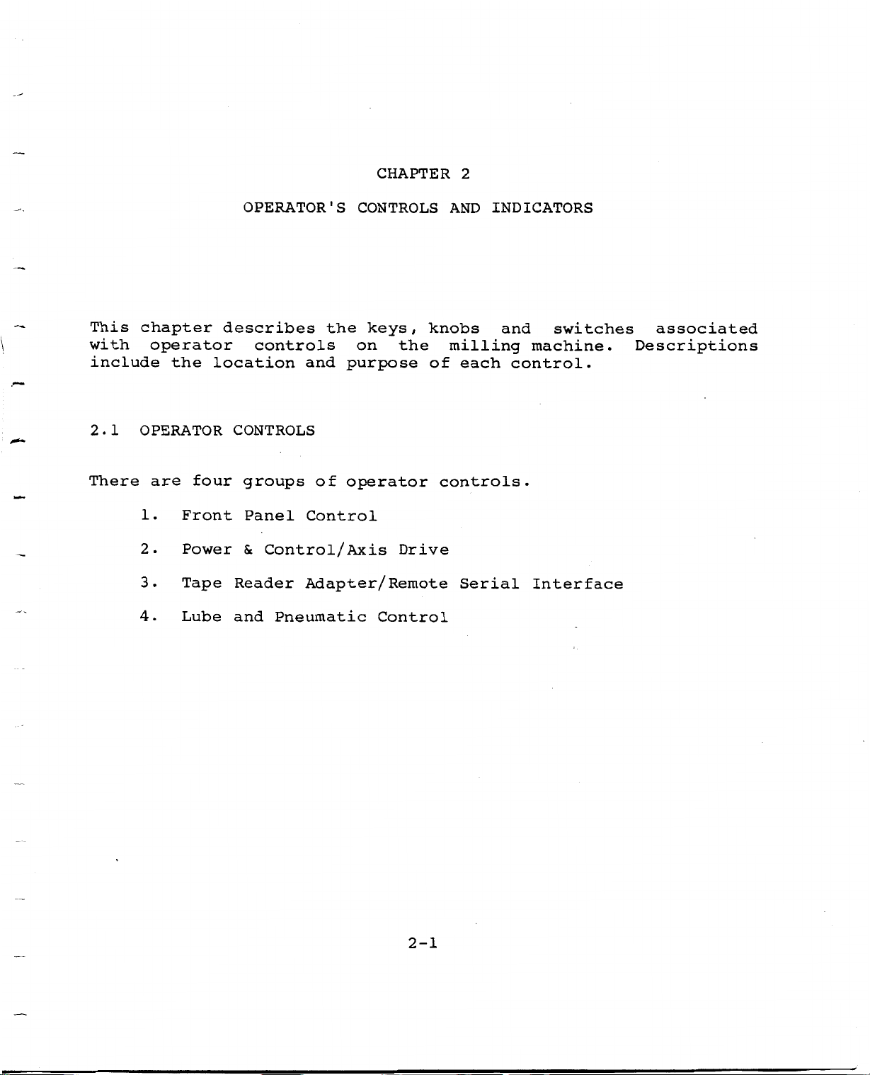
2.1.1
The
Front
control
Panel
Front
Panel
keys
in
the
Control
and
following
operating
switches
groups:
are
color
coded
on
the
The
1.
.
2
.
3
4.
5.
6.
.
7
groups
Machine
EMERGENCY
UP
SET
RUN
Manual
Data
Display
Status
LEDs
mentioned
Controls
STOP
Screen
Input
above
(
MDI
are
)
and
shown
MDI
in
STORE
Figure
2-1.
°£AOCUT
EKCM3CNCY
STOP
|;-i
Figure
i
+
2-1:
COCHWf
I-,
OMU-
i
Iff
Operator's
2-2
'>•
si
''V:
Front
i
Panel
nmwm*
!
i
I
;
nmmm'ÿwuemmr
0
I
J'Ol
9
8
»
*-
,
,
•
!
Page 19
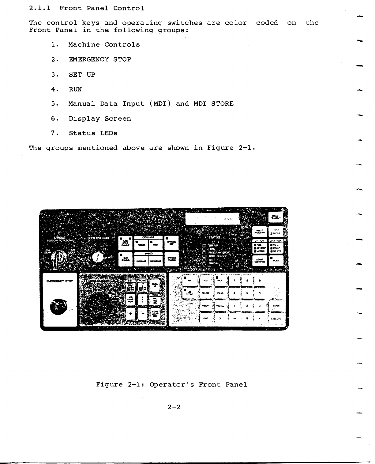
.
2
All
sensitive.
activation
2
FRONT
48
keys
.
PANEL
on
You
the
must
Operator's
apply
NOTE
slight,
Front
but
Panel
firm,
are
pressure
pressure
for
This
keys,
alphanumeric
the
2.2.1
is
24
head
Machine
EMERGENCY
the
color
LED
assembly.
STOP
LCD
Controls
coded
indicators,
screen.
I
£
a
panel
The
P
containing
4
panel
COOCAwT
manual
m
switches
is
48
located
pressure
and
on
a
the
40
sensitive
character
front
4
m
of
Figure
2-2:
Machine
2-3
m
da
|S
Controls
Page 20
Spindle
Controls
.
1
SPINDLE
The
the
pressing
SPINDLE
2.
Simultaneously
moving
or
will
green
safe
LOW
be
OFF:
LED
condition.
SPINDLE
ENABLE:
SPINDLE
GEAR
off)
will
.
will
FOR
be
OFF
pressing
CW
turn
on
when
When
will
ROTATION
the
stop
the
spindle
spindle
the
the
SPINDLE
lever
ON
is
spindle
spindle.
to
(SPINDLE
OFF;
is
ENABLE
either
this
running,
key
HIGH
OFF
is
and
GEAR
LED
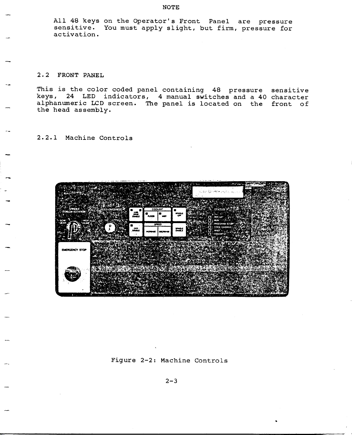
3.
SPINDLE
This
and
spindle
speed
assembly,
FOR
a
is
LOW.
selector
rotation
range
see
Sslftfi
SPL
CW
The
lever
Ml
m
ROTATION:
switch
switch
(
CW
(located
Figure
m
wag!
is
or
2-3.
with
used
CCW)
on
gear
two
to
select
conjunction
in
the
right
A
positions:
the
direction
side
of
with
the
HIGH
of
the
head
Figure
With
spindle
combinations,
cause
SPEED
4.
This
*
only
unless
the
and
was
dial
1
the
GEAR
will
counterclockwise
INCREASE/
allows
while
the
stops
key
speed
released.
located
remains
LO/
GEAR
increases
the
spindle
at
2-3:
Speed
SPEED
rotate
HI/SPEED
DECREASE
key
motor
further
the
at
Spindle
the
center
LO
the
in
rotation.
Key:
or
decreases
is
has
action
level
speed
2-4
Range
or
LO,
pressed.
of
Control
GEAR
clockwise
or
been
the
in
reached
is
the
HI/SPEED
its
to
the
It
turned
direction
indicated
head
direction;
complement,
spindle
will
not
on.
when
the
by
assembly,
HI,
other
speed
operate
Releasing
selected,
button
the
speed
the
will
see
Page 21
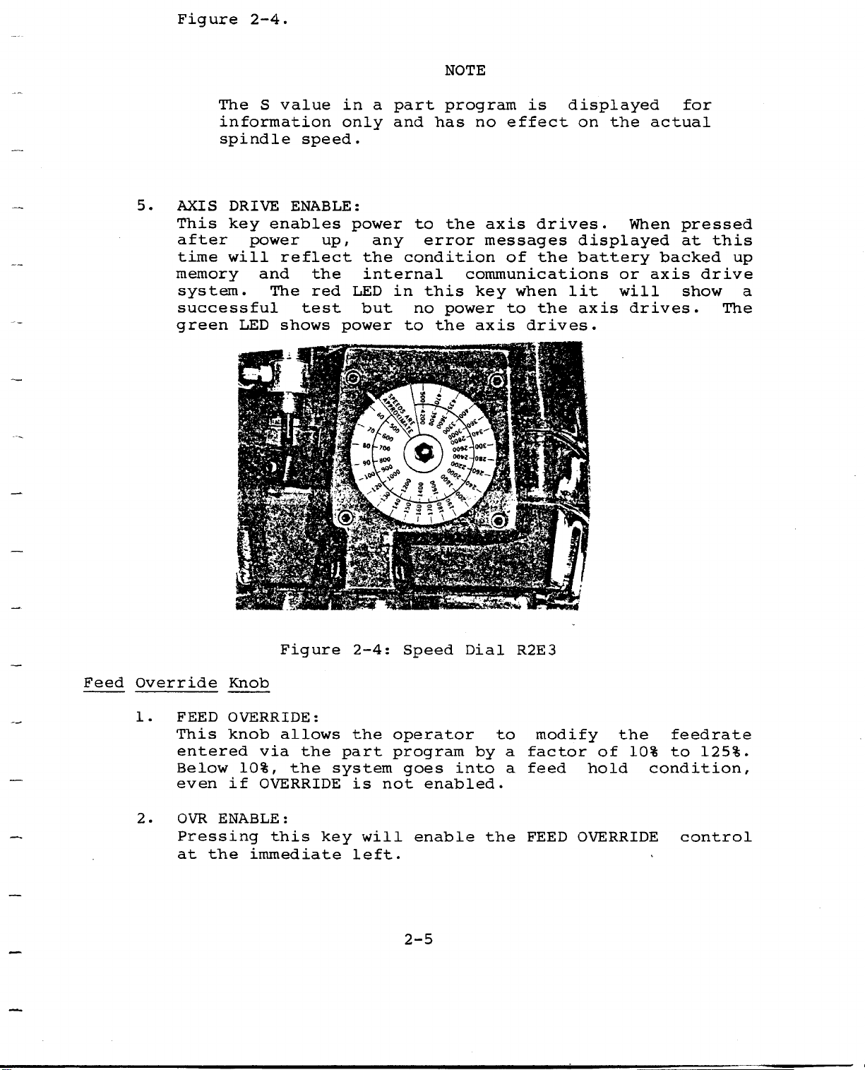
Figure
2-4.
NOTE
5.
The
information
spindle
AXIS
This
after
time
memory
system.
successful
green
will
S
DRIVE
key
power
and
LED
$
value
ENABLE:
enables
reflect
The
shows
i
m
to
to
no
U
l
program
has
the
error
communications
this
power
the
i
\
ooÿÿ00*”"!
VV
%
no
axis
messages
key
axis
5*
m
part
a
in
power
any
the
internal
LED
but
m
r\
a°r>oo
SKL
and
condition
in
f
/
only
speed.
up,
the
red
test
power
ligsysg
\m
......
life
is
effect
of
when
to
drives.
drives.
the
the
displayed
on
the
displayed
battery
lit
axis
When
or
will
drives.
actual
backed
axis
for
pressed
at
drive
show
this
up
a
The
Feed
Override
.
1
2.
FEED
This
entered
Below
even
OVR
Pressing
at
the
Knob
OVERRIDE:
knob
via
10%,
if
OVERRIDE
ENABLE:
this
immediate
Figure
allows
the
the
part
system
key
2-4:
the
is
will
left.
Speed
operator
program
goes
not
enable
2-5
into
enabled.
Dial
by
the
to
a
a
R2E3
modify
factor
feed
FEED
the
10%
of
hold
OVERRIDE
feedrate
to
condition,
control
125%.
Page 22
COOLANT
FLOOD
The
available
operations
OVERRIDE
as
affects
and
for
are
In
MIST
the
well
the
active
Set
as
the
keys
machine.
Up,
control
the
operate
with
Block
feedrate.
feedrate.
the
affects
When
spindle.
NOTE
Run
the
and
the
In
optional
in
MDI
rapid
Auto
use
modes,
(LED
traverse
Run
coolant
on)
the
it
the
FEED
rate
only-
devices
coolant
EMERGENCY
This
is
spindle
and
the
When
destroyed,
STOP,
ENABLE
EMERGENCY
first
sequence
This
threatened.
used
2.2.2
Set
Up
SET
is
milling
includes
diameters,
is
also
paper
data
dark
green
to
activate
tape
from
green
keys
STOP
a
red
motor
system
button
to
intended
machine,
the
axis
used
the
are
but
pull
interrupt
UP
when
or
text
section
the
mushroom
axes
and
set
is
STOP
axis
out
which
is
should
In
in
position
the
returns
normal
axis
for
before
loading
Reference
employing
EZ-LINK
buffer.
of
multifunction
desired
button.
drives.
the
pressed
button,
be
use
of
Points
part
the
function.
System
the
is
each
NOTE
used
use,
motion.
in
the
operation
tool
the
programs
The
Front
and
lost.
and
full
Set
must
When
Program
Start
part
then
axis
only
the
initial
of
length
the
Up
Panel.
be
pressed,
execution
Up
program
To
execute
to
HOLD
the
offset
Clearance
edit
and
keys
pressed
mode.
recover
the
when
button
preparation
part
capability,
clearing
are
Several
and
the
Home
located
more
it
is
TLOs
from
position.
safety
should
program.
values
Point.
part
of
stops
terminated
are
EMERGENCY
AXIS
is
be
of
,
Set
loading
program
in
these
than
the
not
DRIVE
the
This
tool
Up
the
light
once
SET
The
key
SET
key
a
is
multifunction
key
which
allows
the
operator
to
2-6
Page 23

establish
program
Machine
menu
the
various
Tool
reference
Reference
repeated
by
selections.
Length
system
Points
Offset
(XYZ),
(REF
operation
PT
(TLO
a
Clearance
)
for
of
)
the
X
values,
and
key
Point
Y.
establish
(
Scrolling
will
CLR
PT
display
a
part
)
,
through
and
the
2-7
Page 24
OPTION
/OB.
BOPSTOF
i«nwc
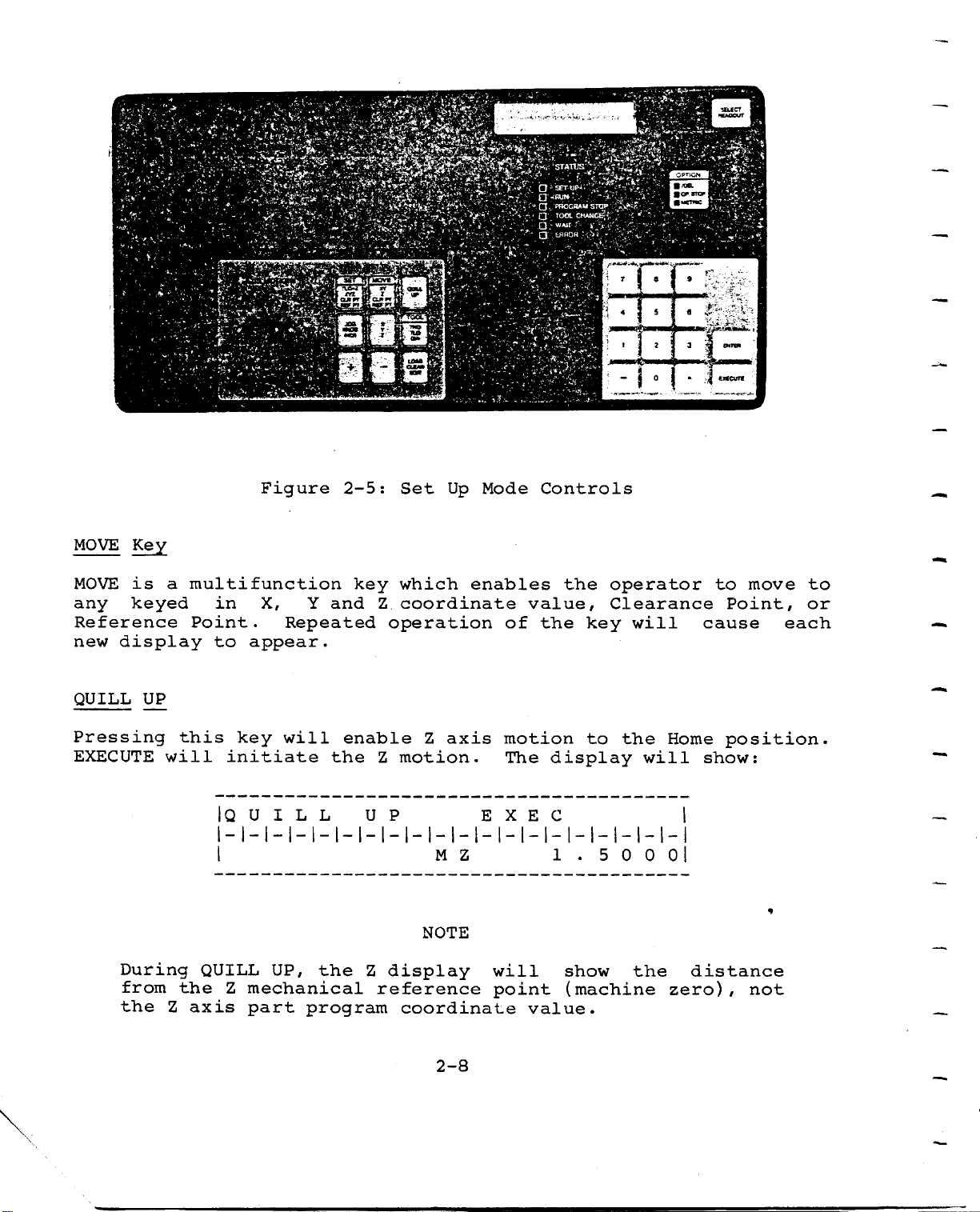
3IKCT
MOVE
MOVE
any
Reference
display
new
QUILL
Key
is
keyed
UP
a
multifunction
in
Point.
to
Figure
X,
Repeated
appear.
jfggffir
Y
and
tfr
2-5:
key
mMovgVr
_
Z
operation
i
8ÿ.
Set
which
Up
coordinate
Mode
enables
of
Controls
value,
the
the
i
r~i
1
operator
Clearance
key
i
7
9
I
1
—
5
*
I
iitjSi&mk,',
*
3
an*
0
will
ExCCUTC
to
Point,
cause
move
to
or
each
Pressing
EXECUTE
During
from
the
will
the
Z
this
axis
initiate
|Q
QUILL
Z
key
will
U
I
L L
UP,
mechanical
part
enable
the
the
program
Z
motion.
U
P
display
Z
reference
coordinate
Z
axis
M
NOTE
2-8
Z
motion
The
EXEC
will
point
display
1.50001
show
(machine
value.
to
the
the
will
Home
distance
zero)
position.
show:
,
*
not
Page 25
JOG/KNOB/
INCR
Key
JOG
The
any
to
TOOL
Repeated
24
tools
the
LOAD/CLEAR/
This
clearing
entering
screen
2.2.3
Run
program
can
through
paper
A
key
AXIS
and
desired
Key
pressing
currently
screen
multifunction
system
part
display
RUN
assumes
exists,
be
entered
the
tape
together
display
EDIT
MOTION
location
program
advances
that
from
EZ-CAM
reader
Key
a
it
of
in
through
key
data
part
will
via
may
with
knob),
the
the
will
text.
remote
the
allows
increments
in
TOOL
tool
T,
enable
from
through
program
necessary
be
serial
be
used
associated
key
buffer.
TLO
various
Each
LOAD,
exists
computer
Port
via
the
will
and
time
operator
as
scroll
DIA
loading
buffers,
the
CLEAR
in
to
terminals,
or
B
the
key
small
The
load
Port
port
ENTER
inputs
key
or
the
functions
to
as
through
for
part
and
is
EDIT.
text
one.
using
A
marked
move
.0001
key
each
program
pressed
buffer.
Part
DNC
C.
(XYZ,
each
inch/
each
will
editing
programs
LINK,
the
"+"
axis
of
scroll
tool.
text,
If
Editor.
,
jog.
the
or
the
no
or
During
program
part
screen
LCD
part
block
program
program
coordinates.
will
Run,
information.
on.
be
the
Run
LCD
The
LED
screen
axis
in
the
will
position
status
display
data
column
the
will
under
current
be
in
the
2-9
Page 26
'
V
&8MB
m
Y&
jl
ffi
'•41
'ÿ
r
COOLANT
*
koQO-.
a
am
SPEED
5W*ttX
ysr-.
Cf*
Wtf
*
rr.
*VJW
OPTION
I'OCL
tit
•UCTMC
_>r*y
StljECT
HCADOUT
*uto
"LOCK
8
Y
33
«U
NO
HOLD
RON
XY2
Si
II
II
£>**,-
SELECT
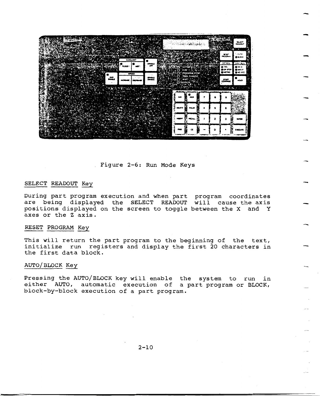
During
are
positions
axes
RESET
This
initialize
first
the
READOUT
part
being
or
the
PROGRAM
will
data
program
displayed
displayed
axis
Z
Key
return
run
Key
the
registers
block.
Figure
.
execution
on
.
part
the
the
2-6:
and
SELECT
screen
program
and
Run
when
to
to
display
idt:
jf
!ÿ}
—
1-1-
part
toggle
the
the
Keys
beginning
Mode
READOUT
WXN*
&
g*
program
will
between
first
rffe
•
T
1
2
•
20
•
Hi
|
3
•
1—1
I
coordinates
cause
the
of
characters
the
-
X
the
and
axis
Y
text,
in
AUTO/
Pressing
BLOCK
either
block-by-block
the
AUTO,
Key
AUTO/
BLOCK
automatic
execution
key
execution
of
will
a
part
2-10
enable
program.
of
the
a
part
system
program
to
or
run
BLOCK,
in
Page 27
2.2.4
Special
Operations
OPTION
OPTION
options
BAUD.
START
START
AUTO/
/CONTINUE
begins
BLOCK
sequence
interruption
It
continue
HOLD
This
key
without
a
to
smooth
Key
is
is
a
multifunction
such
operation
key)
number
such
not
.
stops
loss
stop.
/DEL,
as
Key
either
.
as
necessary
part
of
the
of
at
CONTINUE
PROGRAM
program
program
key
OP.
the
to
which
STOP,
part
top
the
STOP
NOTE
press
execution
position.
allows
METRIC,
program
of
resumes
system
or
this
the
and
the
BOSS
(after
text,
execution
HOLD.
key
interrupts
All
operator
twice
axes
8
i/BOSS
enabling
at
or
will
a
after
to
axis
decelerate
to
choose
4-7,
by
specified
use
motion
and
the
an
In
inches
active
START/
PPRINT
There
represent
part
display
quotation
display
comment
RAPID
is
no
program
will
the
is
TRAVERSE
after
registers
CONTINUE.
key
the
labeled
effect
(MOO,
exhibit
marks
(
first
shown
INSERT
HOLD
M01
1
below:
.500
)
(GO),
,
a
•
40
pressed.
is
are
PPRINT,
a
of
)
M06
comment
Comments
characters.
D
NOTE
motion
not
program
.
When
statement
TOOL
A
I
may
The
lost.
but
beyond
stop
this
END
continue
unused
the
40
An
1
continue,
To
term
command
command
from
characters
example
=
MIL
portion
the
up
is
embedded
reached,
is
program
of
L|
to
of
press
included
will
possible
a
0.2
the
in
between
only
to
the
the
2-11
Page 28
NOTE
When
have
used
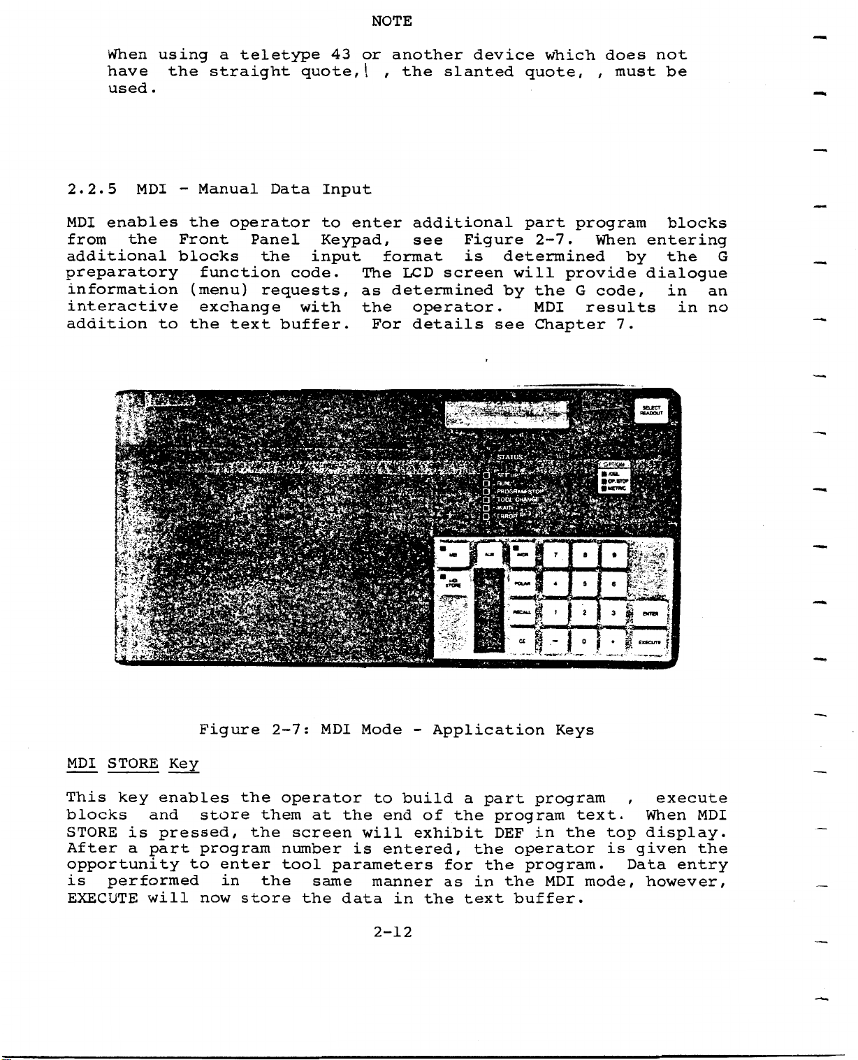
2.2.5
enables
MDI
from
additional
preparatory
information
interactive
addition
the
tm
MDI
!
using
.
to
'
the
-
Front
blocks
a
straight
Manual
the
function
(menu)
exchange
the
teletype
operator
Panel
the
requests,
text
m
Data
code.
buffer.
quote,
Input
to
Keypad,
input
with
43
or
I
enter
The
as
the
For
another
,
the
additional
see
format
LCD
determined
operator.
details
device
slanted
Figure
is
screen
quote,
part
2-7.
determined
will
by
the
MDI
Chapter
see
which
provide
does
,
must
program
When
code,
G
results
7.
entering
by
dialogue
S£L£CT
not
be
blocks
the
in
in
G
an
no
ifp
It
m
la
STORE
MDI
This
blocks
STORE
After
opportunity
is
EXECUTE
key
is
a
performed
Key
enables
and
pressed,
part
will
Figure
store
program
enter
to
in
now
m
sm
nr
M
the
the
store
2-7:
them
the
operator
at
screen
number
tool
same
the
MDI
Mode
the
will
is
parameters
data
-
to
build
end
entered,
manner
in
sram
Application
of
exhibit
for
as
the
the
*
a
the
in
text
4
«OLM
•—.tv.
tr
•
»
/JuTiZI
Keys
part
the
program
program
in
DEF
operator
program.
the
buffer.
text.
the
MDI
JOFSTC**
*
i
mi
«
I
£
S*
£«CUTI
,
top
given
is
Data
mode,
i
5
MB
i
I
.
T
execute
When
display.
entry
however,
MDI
the
2-12
Page 29
Quick
Edit.
Keys
FIND
INSERT
DELETE
RECALL
AUX
-
details
For
INCR
Use
of
specify
to
moves.
cause
go
on.
without
status
the
When
change
addition
-
To
To
search
To
-
To
-
To
-
enable
this
When
G91
a
The
modifying
not
enable
delete
backup
see
key
INCR
of
the
the
the
in
to
to
the
for
the
a
the
MDI
entry
Section
MDI,
in
incremental
LED
inserted
be
key
the
machine.
MDI,
current
part
the
N,
part
in
will
MDI
or
T
entry
edit
of
5.2.
MDI
the
also
part
STORE,
operation
program.
(part
of
program
pointer
S,
STORE,
dimensioning
INCR
in
program
NOTE
new
T
the
work
or
program
text
block
by
or
M
or
key
is
part
independently
buffer.
INSERT
of
one
codes
INSERT
off,
program
the
the
number)
block
allows
system
pressing
The
INCR
system
for
and
of
LED
without
the
key
future
the
the
will
operator
INCR
LED
MDI
will
axis
will
will
mode
reflect
any
POLAR
POLAR
where
axis,
available
"0
-
Numerals
(Minus
"
Minus
this
negative
and
9",
sign
sign
input
R
is
I
in
"
as
Sign)
is
move.
enables
the
&
are
J
MDI,
(Decimal)
needed
required
assumes
replacement
polar
the
Store,
MDI
for
a
radius,
pole
data
for
positive
centers
or
input.
entering
of
A
is
Insert
value.
X,
angular
input
Y
.
The
mode
negative
It
with
distance
POLAR
only.
data,
is
not
R,
function
used
A,
from
absence
for
I,
the
J,
+X
is
of
a
JOG
2-13
Page 30
2.2.6
Status
Indicators
(LED)
current
The
provided
2.3
The
Power
machine,
the
fusible
Main
facing
voltage
voltages
2.3.1
by
POWER
Disconnect
the
is
is
Spindle
status,
24
indicator
&
CONTROL/
Equipment
and
contains
disconnect
Power
volts
600
available
208
230
380
420
460
Motor
or
AXIS
Enclosure
switch
Equipment
AC.
in
VAC
VAC
VAC
VAC
VAC
Protection
mode
lamps.
DRIVE
the
switch.
located
The
kit
50/60
50/60
50/60
50/60
50/60
condition,
is
single
All
Enclosure.
option
form
Hz
Hz
Hz
Hz
Hz
mounted
electrical
incoming
on
of
through
of
the
The
selecting
the
machine
on
the
power
power
upper
maximum
Bridgeport
right
5
control
rear
connection
enters
corner
allowable
incoming
as
of
at
follows:
is
the
to
the
when
line
line
spindle
The
220,
against
becomes
stopping
before
RESETTING
TECHNICIAN,
JOB.
TO
2.3.2
Five
Enclosure.
located
cabinet,
230
the
HEED
Auxiliary
power
motor
or
excessive
excessive,
current
spindle
SERIOUS
THIS
receptacles
They
on
the
see
440
THE
right
Figure
a
is
3
VAC.
currents.
these
to
the
motor
HEATERS
LEVEL
PERSONAL
WARNING.
Power
are
II.
Outlets
found
side
2-8.
phase
Three
spindle.
can
REQUIRES
INJURY
are
directly
of
*
HP
2
heaters
the
If
overload
These
be
restarted.
WARNING
OPERATORS
COULD
provided
cabinet,
the
Correct
AC
protect
current
heaters
QUALIFIED
A
SHOULD
above
as
follows:
motor.
heaters
RESULT
on
the
the
the
It
spindle
the
drawn
by
will
must
MAINTENANCE
NOT
ATTEMPT
FROM
Power
communication
operator
operates
the
shut
be
THIS
FAILURE
Equipment
facing
on
motors
load
down,
reset
ports
the
2-14
Page 31

o
o
o
Dual
4A.
power
and
flood
purchased
Dual
a
standard
When
will
button
Another
option
is
It
receptacles
It
to
the
off
when
coolant
receptacles
the
Main
be
on
is
pushed.
receptacle
when
also
is
for
and
this
fused
are
interlocked
receptacle
spindle
pump
the
are
machine
Disconnect
are
accessory
at
powered
is
when
machine.
powered
light,
NOT
is
available
115/1/60.
with
on
is
off.
switch
affected
is
with
the
when
This
this
with
a
purchased
115/1/60
spindle
the
is
accessory
115/1/60
Tape
on,
is
when
for
Reader
these
the
the
each
motor
spindle
used
and
EMERGENCY
spray
for
fused
drive
to
has
fused
or
EZ-FILE.
receptacles
machine.
the
so
that
is
been
STOP
coolant
at
on,
the
for
2.4
The
PORT
Communications
side
This
panel
interfaces:
PORT
TTY)
RS-232
PORT
A
B
programs.
this
control)
is
Equipment.
remote
supported
Appendix
PORT
C
of
provides
for
are
is
and
C
is
A/PORT
the
provided
for
provided
Power
is
configured
part
provided
There
interface,
Bridgeport's
by
RS-232
pin-outs.
the
both
B
INTERFACE
Panel,
Control
interface
program
on
for
are
EZ-CAM
and
for
see
to
editing.
this
remote
two
RS-491
EZ-LINK
RS-422
the
SUBSYSTEM
Figure
Panel
accept
for
port,
loading
communication
level
and
EZ-FILE
are
Remex
paper
2-8,
is
(operator
three
types
communications
Both
see
2
protocol.
Appendix
and
(EIA
20
down
protocols
standard
systems,
both
available
tape
located
facing
ma
C
The
reader.
the
communication
of
terminal
current
for
loading
for
EZ-LINK
see
on
on
the
machine).
loop
pin-outs.
of
provided
numerical
protocol
Optional
Port
(CRT
B,
left
or
and
part
for
see
2-15
Page 32

.-iÿi
SMfe*
a
-ÿalrSSgSBfe
-<:
rg$j
iÿsii
2i
31ÿ1
JKJ
_
m
'$ÿ1
Figure
2.5
Pressing
start
2.6
The
an
machine),
filling
adjustments
RESET
up.
LUBE
lubrication
enclosure
2-8:
SWITCH
the
RESET
Refer
&
PNEUMATIC
see
oil
.
Tape
and
on
Figure
reservoir
switch
to
the
Reader
Section
CONTROL
pneumatic
left
2-9.
Input
will
3.6.2.
The
levels,
Port
cause
SUBSYSTEM
controls,
side
operator
the
of
&
the
air
the
R2E3
are
is
Serial
located
column
limited
pressure
to
Interfaces
go
into
together
(operator
to
checking,
checks
system
in
facing
and
2-16
Page 33

v>r>-
-j
,.>i—
'
a
;
>&;ÿ
:V-*:
-
rq
-ÿ
;
I
I
A1
v
H
*-VK
-
y
2.6.1
The
automatic
mechanical
this
inspect
refill
system
Lube
the
if
Assembly
surfaces
is
level
the
Figure
lubricating
the
Bijur
of
level
is
<S>
s:
2-9:
in
oil
H
low.
Lube
system
the
tank.
(Sunoco
©
Pneumatic
&
distributes
machine.
The
Waylube
d
•User
tm
Bsa
operator
&
Controls
The
#1180
oil
primary
should
or
all
to
component
periodically
equivalent)
sliding
of
and
An
interlock
SPINDLE
Low
prevent
ENABLE
oil
level
the
is
built
from
spindle
will
into
working
not
from
the
if
stop
lubricator
the
NOTE
being
2-17
low.
but
next
prevent
job.
the
will
which
oil
a
job
started
in
level
progress
for
will
is
too
the
Page 34

2.6.2
Pneumatic
Assembly-
Supply
pressure
Figure
air
reservoirs
glass
marks
The
pressure
pressure
2-9.
filter;
should
.
on
followed
knurled
the
The
to
of
the
be
screw
the
the
indicator
inlet
checked
side
pressure
the
by
over
desired
pneumatic
of
air
daily
the
level.
should
the
indicator
lubricator.
NOTE
air
system
be
pressure
and
filter
is
maintained
regulator
is
between
The
kept
between
will
100
oil
adjust
psi.
at
the
level
the
psi,
80
contains
two
in
indicated
the
air
Normal
see
an
glass
this
2-18
Page 35

CHAPTER
3
.
3
1
four
3.1.1
Before
the
following
following
The
After
operation
START
successful
modes
Prestart
attempting
1.
2.
3.
UP
.
Level
Position
other
Air
procedure
operation
of
Considerations
to
conditions.
of
lubricating
of
parts
pressure
SYSTEM
is
completion
start
X,
Y,
left
level
START
necessary
may
the
oil
&
Z
on
the
adjust
-
UP
/SHUTDOWN
of
the
be
machine,
-
axes
table.
to
system
entered
refill
with
to
start
make
if
respect
nominal
up
start
to
a
low.
the
careful
to
80
up,
begin
psi
R2E3
one
check
fixtures
.
System.
of
the
machine
of
or
3.1.2
Power
power
To
position
the
On
Power
System
up
.
Equipment
the
This
Start
system
switch
Up
Procedure
move
Enclosure
is
the
located
.
MAIN
3-1
DISCONNECT
the
upper
on
switch
right
to
corner
the
ON
of
Page 36

Initial
Condition
There
will
message
During
extensive
successfully
displayed
be
There
corner
problem
When
the
AXIS
following
is
this
be
displayed:
I
|W
period
internal
passes
and
may
be
of
in
DRIVE
:
a
system
A
the
the
ENABLE
I
the
an
T
all
the
red
error
LCD.
system.
self
diagnostic
diagnostic
LEDs
test,
LED
message
This
is
pressed,
the
in
NOTE
are
AXIS
will
illuminated
check.
message
DRIVE
in
alert
the
test,
the
LCD
When
ENABLE
ENABLE
upper
operator
the
screen
as
the
as
AXIS
will
left
part
the
will
following
DRIVES
go
on.
hand
any
of
exhibit
of
system
will
an
EXECUTE
1.
2.
The
AXIS
applied
machine
will
Quill
The
sequence
DRIVE
to
is
in
IMOV
initiate
moves
X
and
ENABLE
the
the
.
Y
axis
Set
ZXY
a
up
axes
green
Up
machine
to
Home
will
drives.
mode.
HOME
LED
homing
position.
move
will
The
sequence:
to
indicate
LED
the
in
X
>
E
E
Cl
I
power
UP
will
positions
has
show
in
been
the
Home
SET
3-2
Page 37

At
the
conclusion
of
this
sequence,
the
display
will
show:
If
the
the
they
LCD
Axis
an
If
the
DRIVE
of
quill
system
bottom
will
will
and
a
If
system
continue
Limit
axis
red
ENABLE
axis
(Z),
be
CRC
LED
limit
|B
(
I
left
displayed
only
prom
will
with
Check
limit
will
is
and
S
0
C
detects
of
has
pressed
the
S
)
1
9
the
displayed
be
error
display
the
been
go
switches,
screen
8
8
a
dead
LCD.
as
is
power
on
the
I
3
error
found
the
up
exceeded
the
in
internal
located
will
TEXTRON
battery,
other
If
codes
after
NOTE
during
error
sequence
AXIS
show:
BAT
system
on
the
message,
.
or
EMERGENCY
DRIVE
logic
in
will
the
system
the
the
INC.
be
faults
lower
has
selftests,
CRC
STOP
ENABLE.
will
check
and
X
and
Y
I
displayed
are
portion
been
will
is
When
the
axes,
detected
of
homed.
the
not
active,
the
status
and
on
the
AXIS
the
The
drive
red
has
automatically
will
appear:
The
AXIS
been
operator
l>
lAXI
DRIVE
disabled.
set
0
IJ
|A
x
ENABLE
S
ENABLE
the
must
G
i
s
LIMIT
LED
Pressing
system
determine
LIMIT
AXIS
indicates
the
in
NOTE
which
X
3-3
AXIS
the
Jog
axis
l-l-l-l-M-l-l
D
R
that
DRIVE
submode.
is
V
I
power
on
S|
E
to
ENABLE
The
a
limit.
the
key
following
f
axis
will
Page 38

The
limit
normal
JOG
"+"
switch.
travel
or
>
I
range
E
keys
When
N
A
the
B
can
the
display
L
E
then
slide
will
AXIS
CAUTION
be
has
used
show:
to
been
DRIVES
move
positioned
away
from
within
the
the
To
correct
active
This
lost
machine
display
the
validate
3.2
3.2.1
Immediately
be
TLO
LED
the
CONDITIONS
Tl.
.
The
indicator
system
1.
guard
coordinate
all
Default
When
system
BOSS
against
jog
until
after
is
forced
relationship
previously
FOLLOWING
Condition
following
quill
the
will
will
is:
8
I
damage
direction.
Home
successful
then
come
Operation
-
the
on
stored
goes
to
next
the
between
position.
START
"Home",
go
on.
the
Software
homing
operator
part
coordinates.
UP
start
into
The
Mode
the
start
machine
travel
operation.
because
program
This
up,
Z
will
Set
up
tool,
coordinates
operation
the
set
be
Up
mode
(default)
limits
the
active
select
equal
and
are
system
and
will
tool
to
the
condition
the
not
the
SET
has
the
now
will
Tl
UP
of
8.
3.
4.
6.
2.
5.
7.
GO
G17
G30
G40
G44
G70
G72
-
-
-
-
-
Rapid
X,
Mirror
Diameter
Constant
Inch
Trans
Traverse
Plane
Y
Data
formation
Circular
Image
-
Compensation
Surface
Input
OFF
3-4
Interpolation
Feed
OFF
OFF
-
Control
OFF
Page 39

9.
G75
Multiquadrant
-
Input
3.2.2
During
error
10.
11.
Self
execution
conditions:
o
o
o
o
o
o
o
G90
DNC
Part
Cutter
Illegal
-
-
Test
program
Absolute
OFF
Diagnostic
of
Compensation
interpolation
Communications
System
Front
Auxiliary
fault
Panel
function
Programming
programs,
data
fault
check
fault
Description
the
input
calculations
command
check
check
controller
following
fault
checks
check
are
made
for
These
code
3.2.3
Errors
screen
messages
Hex
A.
o
o
o
checks
is
Self
which
code
Axis
Tool
Axis
displayed
Test
as
a
and
to
drive
table
overtravel
are
are
4
detailed
a
the
fault
or
not
on
Error
found
character
specific
part
apparent
LCD
the
Messages
by
explanation
check
program
to
during
software
Hex
error
memory
the
the
checking
code.
of
messages
operator
wait
A
the
is
fault
unless
message.
are
displayed
listing
relationship
discussed
check
of
an
the
in
error
on
error
of
Appendix
the
the
3-5
Page 40

3.3
NORMAL
SHUTDOWN
PROCEDURES
To
shutdown
following
3.4
This
activated,
Program
start
The
position
axis
overnight,
procedure:
o
Select
o
Turn
Switch
o
EMERGENCY
should
be
it
execution
up
when
part
program
positions
Block
spindle
machine
STOP
used
deenergizes
is
power
is
lost.
after
or
mode
OFF.
Main
only
terminated
is
restored
and
for
an
or
wait
Disconnect
when
spindle
the
and
to
NOTE
TLO/DIA
will
It
EMERGENCY
an
extended
for
safety
the
spindle
data
necessary
be
a
to
motor
system
are
STOP,
period
tool
not
OFF.
is
and
see
change
threatened.
and
reverts
axes
lost,
to
section
time,
of
block.
axes
the
drives.
but
reestablish
to
axis
4.2.
use
When
drives.
system
the
.
5
3
Loss
cycle)
system
.
6
3
There
POWER
power
of
will
start
RESET
are
FAILURE
cause
up
two
the
to
procedures
different
RESET
RESET
machine
system
PROGRAM
Pushbutton
for
shutdown.
as
operations
key
with
3-6
more
EMERGENCY
involved
switch
than
Return
1/60
of
STOP.
with
of
power
the
second
a
will
following:
(1
require
Page 41

3.6.1
RESET
PROGRAM
Key
This
3.6.2
Pressing
The
3.1.2.
key
1.
2.
3.
4.
RESET
startup
causes
Initialize
Places
Displays
Displays
Either
Or
and
DNC
Pressing
blocks
Pushbutton
this
many
the
first
current
BOSS
BOSS
LINK
RESET
will
pushbutton
procedure
internal
the
line
4-7
8
ON
have
program
pointer
20
characters
operational
I
or
PROGRAM
no
Switch
places
should
operations
OFF
effect.
registers.
the
at
during
the
R2E3
be
to
top
of
first
mode:
execution
in
followed.
be
of
a
startup
performed:
text.
the
line
of
in
part
Refer
text.
the
program
condition.
Section
to
3-7
\
Page 42

CHAPTER
4
4.1
The
up
The
prepare
Set
Panel,
SYSTEMS
Set
Up
after
Set
Up
the
Up
keys
see
1.
2.
3.
4.
5.
6.
OPERATION
mode
the
LED
is
self
in
milling
are
located
Figure
Establishment
Axis
Entering
jog
Loading
Clearing
Editing
OPERATION
the
the
machine
4-1.
tool
part
tool/
functions
default
check
STATUS
in
The
machine/part
of
data
programs
text
IN
condition
diagnostic
column
for
the
following
registers
SET
UP
will
execution
dark
MODE
following
tests
be
of
green
operations
program
have
on.
a
area
system
been
Use
part
program.
of
are
coordinate
completed.
this
the
available:
start
mode
Front
system
to
The
Before
program
will
it
The
instructions
and
sections
entering
ready
be
operation
.
necessary
of
the
to
run
and
Run
mode
in
to
either
explanations
the
system
the
of
text
operation
load
required
are
4-1
buffer.
or
there
create
addressed
If
for
should
ho
a
program.
program
the
the
in
be
a
exists,
preparation
following
part
Page 43

m
i-Wi
m
&HBE
\*
*•
7V
m
13
•W>
,ÿÿÿ;•
V*7**'
?
UK*
m
•’
"'-<*
'**£:»*'
serVÿuovi
M»=l’
if
2§i
u-i
+
1
ft
aw
KPS??*?!
u
J.
.
-
ft-Ww
SWpV|
,v
,
-
"«.
'
'•
•-
->
'
O
-
n
wocjÿHSTW;\r;y;ÿ:!
‘
TOOL
CHANGE
Q
ERROR
,
"
’.
-.,
iHfUl
'
'**
3"«agW«w
muter
KAP0U1
t#
I
.
[-B4"7
iLlis*
I
ft
I
3
si
E*nD<
I
i
'
i
4.2
The
.
(machine
with
4-2.
part
coordinates
For
also
convenience
and
the
MACHINE
R2E3
control
coordinates)
respect
The
to
be
convenience
be
designated
independent
operator
COORDINATE
contains
to
the
operator
machined,
.
in
for
the
through
Figure
SYSTEM
that
Home
may
establish
which
programming,
where
programmer
coordinate
the
4-1:
an
continually
position
SET
Set
internal,
is
a
all
or
system
XYZ
4-2
Mode
Up
of
the
a
Reference
expressed
part
and
X
operator.
which
function,
Keys
absolute
tracks
machine
program
Y
axes
can
see
Point,
in
This
reference
each
axes,
these
zero
moves
is
set
be
Section
axis
based
will
a
manually
position
see
absolute
point
separate
4.5.2.
system
Figure
on
provide
the
can
by
Page 44

21-1/2
TOTAL
OPENING
2
5
*
QUILL
IN.
TRAVEL
CAUTION
WITH
POSITION.
WOULD
-
QUILL
TABLE
SPINDLE
BE
DOWN.
IN
ITS
1/2
"CLEAR
X
I
*
UPPERMOST
GAGE
LINE
WITH
THE
A
Z
*
MACHINE
"HOME"
XBY
(BOSS
BORED
AXIS
PROVIDED
3/8"-
4-
x-8-3/4
—
+
5.5
5“
I
I
COORDINATE
POSITION
ZERO
HOLE
POINT
FOR
CUSTOMER)
BY
/
1
....
.
t
Figure
4-2:
TOTAL
WORKING
Machine
MACHINE
MACHINE
42"
7
7
/
1
]
r
34"
SURFACE
Coordinate
TRAVEL
z
z
17"
ENVELOPE
COORDINATE
X=8.75,
System
Y
=
DISPLAY
5.55
1
12-
1/2
1
"WORKING
SURFACE
4-3
Page 45

The
operation
operator,
change
The
the
in
point
•use
Clearance
.
X
and
machine
will
of
the
.
which
Y
be
two
Point,
This
will
Reference
absolute
expressed
reference
is
an
allow
Point
can
be
arbitrary
adequate
and
coordinate
in
its
systems
the
own
used
clearance
Clearance
system.
independent
two
has
during
point,
useful
the
established
during
Point
The
coordinates.
tool
are
part
advantages.
program
change
by
the
expressed
the
tool
zero
The
During
displayed
The
machine
CLR
are.
keyed
4.3
Pressing
following
1.
2.
part
PT
AXIS
It
allows
coordinates
part
It
provides
workpiece
program
on
coordinate
QUILL
and
in.
JOG
the
display:
|J
|X
the
part
of
being
the
produced.
is
LCD
UP
way
a
moved
execution,
values
(and
JOG/KNOB/lNCR
G
0
.
9
0
0
0
the
to
will
the
key
program
programmers
from
to
regain
be
are
its
the
in
shown
the
position
the
corresponding
the
X
Y
first
.
5
0
be
choice,
part
X,
part
only
0
0
written
program
in
Y,
program
when
designations
time
regardless
the
or
SET
will
in
convenient
zero
fixture.
Z
coordinates
coordinates.
REF
cause
I
in
of
if
PT,
the
the
SET
MOVE)
the
Pressing
the
selected
condition
be
the
To
select
use
READOUT
or
the
the
the
for
power
the
upper
key
Z
coordinate
is
"+"
JOG
up
JOG
or
axis
is
state,
axis
screen
pressed,
in
JOG,
following
desired,
value(s)
key
the
will
it
X
will
will
designated
axis,
read
in
4-4
initiate
continuous
system
press
JOG
alternately
the
lower
the
X,
continuous
direction.
start
X/Y/Z
or
Y
half
motion.
up.
Z.
exhibit
of
key;
When
the
the
motion
The
This
after
the
X
screen.
default
will
each
SELECT
and
of
Y,
Page 46

OPERATION
IN
SET
UP
MODE
Examples
use
To
keys
,
display
screen
rotation
in
the
X
axis
clockwise
of
the
press
JOG
.
of
axis
left,
counterclockwise
included
will
chosen
provide
.
the
|J
lx
|J
O
0
0
LCD
G
.
G
screen
0
0
With
0 0
With
displays
X
axis
axis
Z
X
Y
Z
l-l-l-l-l-l-l-l-l-l-l-l-l-l-l-l-l-l-l-l-l
Z
AXIS
the
KNOB.
Axis
the
and
Y
rotation;
one
in
approximately
MOTION
motion
knob
direction
axis
direction.
full
knob,
motion
JOG/KNOB/lNCR
The
will
out,
rotation
key
XYZ
will
cause
or
complimentary
then
chosen.
.002
will
be
approximately
Z
There
of
inches
are
selection
.
0
selection
.
0
independent
key
bring
controlled
Positive
axis
are
knob;
the
shown
0
0 0
again
up,
of
0 0 0
0
the
motion
50
motion
below:
0
of
and
the
desired
the
by
inch
0.1
approximate
is
each
initiated
detent
detent
the
is
in
"+"
screen
axis
knob.
of
by
positions
the
or
will
to
Full
motion
motion;
by
position
axis
the
a
the
If
still
axis,
or
"+"
inch
indicating
4.4
Specific
selected
for
ENTERING
tool
the
of
greater
third
keys
incremental
desired
|J
tool
to
machine
data.
function,
again,
0
TOOL
lengths
precision
direction
G
INCR
DATA
a
making
motion
and
part.
motion
of
INCR,
each
must
diameters
The
is
in
4-5
pressed.
key
the
be
Z
Z
0
must
following
required
is
activation
desired
pressed
.
0
0
0
entered
be
information
This
direction.
for
0
to
will
initiate
each
position
enable
jog.
I
for
is
the
0.0001
The
tools
needed
the
the
key
Page 47

OPERATION
IN
SET
UP
MODE
The
be
tool
execution
Up
c
'HP
4.4.1
mode
|
1.
2.
data
retained
data
by
/
The
control
manually,
embedded
Manual
Tool
6.5536
Tool
in.
stored
may
via
manually
Length
in.
Diameter
(8323mm)
in
in
be
entered
part
memory
but
the
in
Knee
Offset
(166.46mm)
the
memory
program.
overwriting
can
not
part
Adjustment
(DIA)
R2E3
(approx
through
will
program
be
(TLO)
values
tool
Old
NOTE
retain
over
buffers
year)
1
statements
tool
the
written
when
values
maximum
-
data
old
the
it
is
with
entries.
last
by
is
maximum
entry
nonvolatile,
the
preceeding
be
may
value
different
executed.
is
power
updated
entry
+/-3.
it
off.
entered
values
2768
will
New
program
in
Set
is
necessary
is
It
the
change
portion
height
programmed
workpiece
1.
2.
3.
requires
of
of
Place
piece
Return
to
.
0
Crank
not
work
equals
provide
change
off
the
tool.
5
the
an
inches
the
have
to.
for
in
excess
tool
knee
the
longest
to
the
quill
arbitrary
knee
penetrates
piece
at
adequate
position
work
tool
.
upward
above
least
adequate
holder
should
table.
to
piece
changes.
of
tool
the
but
until
the
the
2
clearance
perhaps
and
2
11/16
which
be
Home
work
table
3/4
clearance
Minimum
inches,
inserts
adjusted
in
the
position,
convenient
tip
of
piece.
plus
inches,
for
CLEAR
the
fixture
between
machine
distance,
the
the
tool
to
obtain
clearance
the
into
using
then
tool
If
the
changes.
POINT
the
and
the
preset
the
length
clamp
set
just
knee
would
that
for
spindle.
the
the
for
height
0.5
height
Such
be
clearance.
tool
a
of
longest
the
Z
example;
touches,
of
inches
located
and
tool
the
The
work
axis
the
will
tool
4-6
Page 48

OPERATION
IN
SET
UP
MODE
4.4.2
TLOs
through
SET
Use
premeasured
are
Key
the
system
When
in
tool
To
key
of
the
the
number
bring
.
the
TLO
entered
part
SET
to
SET
upper
another
Each
24
Input
programs.
key
and
determine
key
shown
|S
IT
time
numbers.
left
E
through
when
it
the
is
pressed
in
T
1
0
tool
TOOL
is
of
the
T
L
number
is
TLO
TLO
offset.
the
lower
0
pressed,
=
value
necessary
ojice,
screen
Z
=
to
Z
right
M
the
on
the
screen
the
for
to
with
.
EXEC
Z
screen,
the'
use
screen
the
1
0
SET
will
tool
the
will
current
.
0 0
you
key,
machine
must
scroll
has
display
0|
0
TOOL
value
use
through
key
not
coordinate
TLO
for
the
or
been
=
the
TOOL
each
Z
Insert
to
the
move
the
Ins
numbe
touches
EXECUTE.
each
To
the
"Z"
t
dr
3?ÿ.
tool
display
bufferÿ
the
desired
1.
2:
'
the
table
zero
the
v
longest
in
quill
usually
next
With
top
he
'
Continue
programmed.
specific
a
use
number:
Enter
to
SET
that
Continued
scroll
number
and
the
tool
the
desired
(Z
axis)
tool
incremental
of
the
until
TOOL
the
the
tool
TLO
tool.
activation
through
into
selected
into
so
the
the
in
workpiece,
tool
key
number
Z
=
each
the
that
top
jog,
all
number
and
to
active
tool
the
location.
of
machine
move
TLO
either
desired,
finish
of
tool
will
machine
the
the
or
values
from
TOOL
number.
buffer.
Using
tip
of
work
and
key
the
"Z"
the
of
then
entering
will
appear
and
piece.
Z
zero
have
two
axis
Return
clamp
the
the
tool
the
in
until
point,
been
carried
24
techniques
press
the
cause
EXECUTE
in
the
the
work
incremental
just
correct
the
and
determined
in
ENTER.
offset
the
display
will
to
SET
display.
top
the
to
value
load
TLO
piece
Jog,
touches
tool
just
press
tool
select
Return
that
for
for
=
to
Z
4-7
Page 49

OPERATION
IN
SET
UP
MODE
NOTE
The
Reference
TOOL
The
see
as
values
Key
TOOL
Figure
tool
Pressing
number
(prompt
EXECUTE
next
To
tool
load
display
followed
keyed
Z
key
diameters
using
1
in
the
in
display
4-3.
TOOL
through
upper
loads
number.
tool
TOOL
ENTER,
by
tool
IT
IT
Point
can
the
will
the
T
number.
O
o
exhibits
(Home),
be
used
This
directly
Keypad.
scroll
24.
screen)
contents
buffer,
to
which
O
L
when
will
through
ENTER
press
the
brings
the
not
tool
allow
into
loads
into
into
screen.
distance
part
you
the
the
the
T
l-l-l-l-l-l-l-l-l-l-l-l-l-l-l
i
/
.
1
5
0
2
0
the
the
the
the
program
lengths
to
tool
tool
contents
lower
tool
TOOL
The
message
/-
from
have
enter
buffer
data
table
key
tool
0.50001
the
mechanical
Z
coordinates.
been
values,
TLO
keying
by
table,
the
of
screen
and
once
number
TOOL
to
l-l
premeasured,
from
input
display
brings
bring
keyed
is
TLO
for
as
in
up
well
the
tool
field
and
the
the
in,
the
The
to
data
the
different
ENTER
change
next
Entering
active
that
last
entire
same
be
without
field.
tool.
numeric
procedure
entered.
buffer
will
a
tool
input
tool
T
numbers
keying
take
value
and
CE,
character
field.
will
Pressing
and
place
will
the
CLEAR
return
in
ENTRY
also
and
numeric
and
set
screen
entered.
allow
EXECUTE
screen
the
their
data
screen
the
the
input
will
key,
4-8
the
will
values
display
pressed
Pressed
tool
display
will
display
tool
diameter
introduce
can
be
generate
number
the
once,
twice
these
TOOL
to
entered.
will
advance
as
TLO/DIA
will
it
will
(TOOL
T
a
the
delete
values
so
Pressing
null,
current,
values
delete
to
DIA)
to
that
no
the
for
the
the
Page 50

Q
O
a
D
w
01
a
a
H
$
w
O
G
I
b
Q)
§
01
(0
aj
•
1?
JBB-.
;/
m
'v!
‘•r
/ÿ
/
\\
w
m
;T.'v
,V'\
,‘.iv
;ÿ•'
,
Wi!
.*
$
IH
o
EH
-p
T
i
0)
01
0)
&
M.4
i
l;A
%
ft
ro
4
0)
p
01
I
!
;
I
:
!
!
i
i
I
1
I
I
Page 51

OPERATION
Programming
New
TLO
part
moved
is
already
by
4.4.
program.
defined
TLOs
3
into
Tool
IN
SET
values
the
exists
contained
Diameters
is
UP
can
When
tool
executed.
for
be
a
in
MODE
entered
TLOs
tables
particular
the
are
part
until
by
entered
Note
tool
program.
defining
the
block
that
this
it
if
will
their
way,
in
a
TLO,
not
values
the
which
other
be
values
the
overwritten
in
TLO
than
the
are
the
not
data
zero,
Tool
the
When
the
diameters
part
the
part
4.4.4
Differences
losses
one
called
for
tool
8
that
pathway,
I
firmware.
1.
program.
tool
program,
Cutter
during
difference.
Calculation
The
of
Example
are
diameter
Diameter
in
tool
regrinding.
for
in
based
compensation
the
programmed
:
Programmed
Actual
entered
This
Cutter
diameter
the
on
is
(s)
are
Diameter
Compensation
part
Provision
those
compensation
of
value
Cutter
Cutter
two
ways,
the
same
not
are
When
program,
differences,
diameter
with
as
the
Compensation
to
due
a
tool
the
automatically
to
.
value
to
be
and
.500"
=
.485"
=
the
described
same
wear
diameter
operator
is
entered
the
Dia.
Dia.
as
during
embedded
actual
End
End
TOOL
those
must
must
is
key
for
called
be
is
less
calculate
the
diameter.
Mill
Mill
or
TOOL
used.
use
than
compensate
the
in
difference
through
TLO.
for
and
a
BOSS
by
to
the
new
If
the
than
will
Compensation
the
actual
input
that
always
.485"
.
-
-.015"
cutter
value
programmed
positive.
be
500
entered
is
Actual
Programmed
"
Dia.
is
smaller
always
was
4-10
is
negative.
used,
:
-.015"
than
the
that
a
If
larger
compensation
programmed,
cutter
value
Page 52

2.
Entry
in
Set
Up
mode
OPERATION
IN
SET
UP
MODE
3.
o
Enter
conformation
o
Continue
desired
o
Press
o
Key
section
o
Press
Entry
Cutter
the
program
activated
or
G42
Example
ENTER
in
EXECUTE
part
in
Diameter
beginning
using
when
function
:
T1//.5
T2//
T3//.187
Set
Up
is
press
to
appears
to
compensation
on
the
to
program
Compensation
of
the
Tn/
cutter
.
.25
mode
on
the
the
on
the
scroll
Keypad.
insert
the
d
command.
compensation
Tool
-
Tool
-
Tool
-
and
LCD
TOOL
screen,
through
value
value
program
#1
#2
#3
press
screen.
hey
from
values
.5"
.25"
.187"
until
upper
TLO
numbers
into
text,
These
is
the
the
line.
and
DIA.
in
the
tool
may
or
turned
Compensation
Compensation
Compensation
programmed
be
embedded
values
TOOL
tool
the
on
number
yellow
buffer.
in
will
by
a
hey,
at
the
be
G41
Note
tool,
part
The
new
program.
BOSS
points
motion.
within
program
stored
4.5
Reference
depending
the
SETTING
Reference
that
it
if
will
8
Such
the
text
values
coordinates
a
cutter
be
I
Control
for
points
control.
containing
of
REFERENCE
on
the
Points
diameter
overwritten
for
tool,
the
generate
This
the
compensation.
POINTS
are
reference
and
Cutter
ahead
tracked
their
already
cutter
by
Diameter
of
new
data
preparatory
system
applicable
4-11
exists
diameters
the
blochs
is
by
chosen.
Compensation
currently
dependent
functions
two
tracking
for
of
separate
Table
a
contained
programmed
data
upon
and
the
4-1
registers.
particular
in
computes
internally
the
stored
use
registers,
summarizes
the
tool
of
Page 53

OPERATION
IN
SET
UP
MODE
REFERENCE
.
1
Machine
2.
.
3
4.
Table
When
a
part
Home
This
new
POINT
Reference
Part
Clearance
setting
program,
operation
is
reference
Program
4-1:
only
Reference
the
various
it
then
necessary
point.
TRACKING
REGISTER
Machine
Machine
Part
Machine
is
important
follow
Coord
Coord
Program
Coord
Points
NOTE
reference
the
if
the
and
to
order
operator
Z
Z
XYZ
Z
Tracking
points
begin
shown
AXES
INVOLVED
Home,
Home,
Home,
Registers
before
with
in
desires
XY
XY
XY
the
Table
to
Home
to
Position
to
Position
running
machine
set
to
4-1.
a
4.5.1
Reference
The
relative
each
a
values
Reference
Reference
the
from
SET
coordinate
pick
PT
part
axis
axis)
bore,
REF
setting
program
home)
Reference
from
fixture
its
PT
up
the
to
.
Use
dowel
the
Point
Point
or
originally
ISET
I
|X
allows
system
part
is
zero
.
The
Point
the
pin
absolute
register.
will
9
optional.
Point
machine
JOG
to
or
allow
the
work
clamped
REFPT
.
5
you
from
program
are
following
will
move
other
to
set
provide
coordinate
the
location
coordinate
a
return
piece
position.
define
which
coordinate
If
this
to
the
sequence
axes
to
determine
X
I
6
Y
a
convenient
indicator
feature
machine
absolute
zero
to
edge.
registers
to
an
.
0
system.
should
points
a
convenient
EXECUTE
important
I-
devices
is
coordinate
be
coordinate
whether
I-
I-
point
The
used
used
to
use
(Home
will
I
I-
I
in
can
the
with
location;
the
location
it
has
the
be
of
CLR
zero
REF
values
site
load
machine
moved
machine
used
the
PT
PT.
for
the
on
to
REF
and
(X,Y
4-12
Page 54

OPERATION
IN
SET
UP
MODE
Failure
result
4.5.2
Use
JOG
point
tool
negative
with
XYZ
1.
2.
3.
Zero)
.
and,
Reference
Part
Clearance
Part
to
(The
the
to
in
and
Program
place
usually,
Z
axis
SET
Program
set
loss
the
Clearance
the
axis
Z
position.)
key.
Point
Point
the
Zero
X,
the
Zero
machine
of
Y
will
lowest
the
(SET
and
Point
Point
be
When
NOTE
Reference
XY
offset
values.
XYZ)
Z
axes
determined
depth
axes
at
for
are
Point
values
the
relative
that
in
(Part
part
tool,
position,
'iA
first
program
to
will
Program
the
the
key
longest
most
in
zero
SET
The
each
appears
the
reflect
operator
axis
on
program,
the
QUILL
TLO
the
|S
lx
has
keying
by
the
the
coordinates
UP
or
from
E
T
1
upper
axis
M6
the
.
the
XYZ
5
0
choice
in
portion
coordinates
cancels
tool
0 0
the
from
of
numbers
the
table.
assigning
of
part
NOTE
SET
X
Y
.
4
as
the
screen.
which
programming
and
Z
0 0 0
0
any
appropriate
the
appear
automatically
coordinate
During
the
in
zero.
I
value
axis
execution
screen
loads
to
prompt
of
will
4-13
Page 55

OPERATION
IN
SET
UP
MODE
4.5.3
QUILL
Use
and
X
the
where
change
other
.
coordinates
4.6
When
MOVE
MOVE
coordinate
of
the
the
.
XY
initiate
axis
will
Clearance
UP
Y
Enter
OPERATION
is
X
value
When
plane.
Point
move
to
axes
operations
as
the
|S
E
to
SET
T
any
CLR
the
CLR
C
can
PT
L
l-l-l-i-l-l-l-l-l-l-l
|M
pressed,
value
Y
motion.
X
1
of
into
is
MOVE
.
7500
X
a
entered,
Z
the
is
buffer
will
axis
Z
convenient
take
and
PT
coordinates.
R
P
T
screen
keyed
and
EXECUTE
do
the
to
place
press
Y
in;
advance
same
the
point
EXEC
3
will
ENTER
will
Home
away
.
program
eg
EXECUTE
.
5
2
read
will
the
initiate
the
in
position.
from
to
0
0
MOVE
load
entry
Z
load
the
stop
I
field
axis
axis,
XY
the
work
the
Then
or
X
and
contents
to
motion
EXECUTE
piece
tool
and
the
jog
Y
the
Y
in
When
MOVE
coordinates
current
initiate
axes
When
current
The
in
to
MOVE
previously
the
CLR
position
motion
the
REF
position
upper
|M
|X
|M
I-
of
CLR
|C
|M
0
1
0
I-
I-
PT
PT
X
X
PT
stored
screen.
V
.
V
is
the
is
4
1
is
7
I-
pressed,
shown
and
.
.
.
pressed,
are
X
Y
5
0
0
Z
I-I-
M-
previously
move
3750
7500
displayed
coordinates
EXECUTE
in
the
I-
Y
I-
the
the
Y
Y
the
X
.
0
Z
1-1-
I-
0
Z
upper
established
lower
quill
.
2
.
0
absolute
on
the
for
will
7
3
I-
I- I-
.
7
screen
to
the
0
0
5
2
lower
Reference
move
5
0
5
0
screen.
0
0
0
0
the
l-l-l-l-l
0
I-
I-
Clearance
Home
I
0
will
position
coordinates
part
Point
axes
display
Point;
EXECUTE
of
the
will
to
the
will
and
of
screen.
appear
REF
the
the
the
the
PT
.
4-14
Page 56

OPERATION
(+Z)
Z
A
axis
move
up
will
occur
before
the
X,
and
IN
Y
SET
axes
MODE
move.
UP
.
4
Part
4.7.1
7
LOADING
programs
1.
Teletypewriter
.
.
Baud
Paper
EZ-FILE
*
Remote
EZ
2
3.
4.
5
|R
|M
PART
-CAM
Rate
X
X
can
tape
computer
.
4
3750
.
1
7500
PROGRAMS
be
loaded
by
console
Y
Y
any
.
0
0
2
.
0
one
0 0
5
0
0
2
of
the
following:
It
is
within
OPTION
screen
The
initial
in
another
Port
for
EXECUTE
baud
2400,
rates
If
maintain
first
the
key
will
4800
any
control
to
A
and
will
available
and
other
necessary
display
show:
|0
P
[
A
I
values
baud
enable
initiate
9600.
the
to
T
]
3
displayed
rate,
baud
existing
to
match
the
BAUD
0
0
followed
the
in
rates
baud
baud
action
this
rate.
set
the
are
selection.
[
B
will
by
rate
with
system
NOTE
attempted,
the
peripheral
[
]
be
A
9
ENTER,
transmit/
]
6
the
for
this
are
0 0
Port
equipment.
In
current
will
newly
110,
the
receive
this
setting.
store
B
to
entered
300,
system
selection,
l-l
the
be
600,
baud
Scroll
new
entered
rate.
will
rate
the
the
Keying
rate
.
The
1200,
4-15
Page 57

OPERATION
IN
SET
UP
MODE
4.7.2
After
through
connectors
Enclosure
Input
setting
the
a-.:;
r>.
£
r:
M.
t-
:
baud
Peripheral
rates
From
LOAD/CLEAR/EDIT
on
located
.
•V
the
n
.
»•
•>.
m
if
>'$£%:
§nmm
-m
loading
key,
left
»
\
•ÿC.lj'.f
*.?f-
Equipment
from
the
side
mmm.
?
peripheral
screen
of
f:
»
j;
n
r-;
“<•
*
INDEX
display,
the
I*
•
|Ssfi£S
ItllSl
devices
Power
3®
and
m
39
will
the
plug
Equipment
be
PORT
option
display
The
through
device
enable
and
the
C
shown
.
lower
(REM).
M
a
*
screen.
Figure
This
the
a
the
ti
4-4:
in
Figure
is
done
following
|L
0
A
l-l-l-l-l-l-l-l-l-l
|0
P
T
screen
paper
prompt
provides
tape
When
chosen
will
D
R
"0",
Plug
4-4,
through
message
1
reader,
device.
appear
Connectors
accepts
C
N
D
the
"1"
or
at
LOAD
the
after
l-l-l-l-l
R
2
option
LINK,
DNC
,,2"
EXECUTE
the
4-16
for
paper
the
/CLEAR/
pressing
M
E
of
or
keyed
is
will
extreme
Communications
tape
ED
IT
LOAD:
I
loading
a
enter
part
remote
in,
lower
reader/
key
l-l
program
communication
EXECUTE
LOAD
the
left
which
submode
portion
loader
will
text
will
of
Page 58

OPERATION
IN
SET
UP
MODE
LOAD
If
LOAD
the
currently
storage
LOAD
into
computer
the
LCD
FROM
R2E3
device.
FROM
R2E3
display
REM
REM
text
stored
REM
that
|L
A
O
D
R
P
T
*
selected,
is
|L
0
1
loads
with
text
supports
|L
O
A
F
ROM
memory
in
program
memory
will
0
A
.
D
REM
part
a
from
the
the
show
D
D
E
the
REM
program
Port
R2E3
number
from
EZ-LINK
the
:
screen
:
1TO
B.
text
the
following:
will
(per
LOAD
memory
loads
EZ-FILE,
protocol.
CHAR
l-l-M-l-l-l-l-l-l-l-l-l-l-l-l-l-l-l-l-l
.
IN1G00G90X4
Y4.
display:
REM
RS-491-II
TO
REM
out
the
8
T1M06
reads
specified
EZ-CAM
At
the
5
2
protocol)
the
to
the
or
end
I
program
remote
program
any
LOAD,
of
into
Host
To
will
The
part
space
device
DNC
1
2.
abort
set
All
data
DNC
programs
OFF
.
new
.
LINK
in
(EZ-CAM
is
The
characters
to
12000
The
lower
the
loaded
LOAD
system
the
data
is
the
text
the
upper
progress,
in
is
designated
longer
or
default
screen
present.
characters
screen
program;
to
loaded
than
memory.
EZ-FILE)
will
press
CLEAR
at
primarily
100
The
condition.
will
The
in
exhibit
up
and
NOTE
the
feet
program
acting
4-17
show
system
the
to
the
terminate
end
in
text
the
characters.
20
LOAD/
of
to
allow
length,
is
as
the
the
is
buffers.
total
capable
first
CLEAR/
the
previously
the
the
run
excess
block
ED
LOAD
maximum
with
of
IT
program.
R2E3
storage
number
storing
of
key.
stored
to
the
data
This
execute
storage
remote
space.
of
up
in
Page 59

OPERATION
IN
SET
UP
MODE
Part
the
Figure
programs
Editor.
bring
system
The
instruction
4.8
To
key
CLEARING
clear
is
diplay:
4-4,
the
while
following
|E
*
is
in
various
out
pressed
1C
l-l-l-l-M-l-l
|0
can
This
D
now
editing.
DATA
L
E
R
I
U
also
the
T
in
2
A
N
be
uses
LOAD
screen
the
data
times
R
loaded
the
Port
/CLEAR/
display:
EDIT
or
text
followed
1
P
R
mode,
G
from
A
ED
in
M
a
receptacle
IT
key
refer
memory
by
teletypewriter
is
EXECUTE.
O
2
T
at
pressed
to
the
L
0
the
3
I
Chapter
LOAD
The
I
through
lower
left,
times
5
/CLEAR/
screen
EDIT
will
to
for
When
following
CLEAR
0
entered
1
CLEAR
following
"0",
1C
10
o
o
o
"1",
action.
RUN
in
PRGM
will
L
E
A
L
CLEAR
text
CLEAR
program
PRGM
the
the
clears
the
A
L
or
system
clears
be
R
PRGM
area.
MAC
NUM
single
upper
"2"
displayed:
1
M
text
-
out
A
ALL
("1")
When
digits
screen,
is
run
C
up
the
out
("0")
entered,
part
registers.
the
clears
to
the
a
number
1
the
clears
or
EXECUTE
program
part
<
out
first
of
)
0
figure
P
out
the
up
is
will
run
also
It
program
G
R
M
the
macro
designated
to
5
entered
interpreted
is
buffer
l-l
|
>
entire
digits
bring
aborts
text
library
after
and
DNC
part
program
(other
the
about
any
area.
(all
prompt
as
link.
program
number)
a
the
data
The
part
.
than
in
part
4-18
Page 60

OPERATION
IN
SET
UP
MODE
program
and
CLEAR
2
4.9
Editing
insert,
buffer.
three
Using
keyboard
text.
exhibit
if
TOOL
EDITING
is
modify
This
times
the
It
a
found,
possible
.
EDIT
is
is
"*“
|E
I-
I*
number
clears
or
is
key,
used
entered
indicating
D
I-I-I-
.
will
out
while
delete
entered
a
to
I
T
The
delete
the
local
modify,
by
pressing
I- I- I-
R2E3
in
blocks
by
EDIT
1-1-
will
that
tool
Set
pressing
console
locate
is
1-1-
search
program
data
Up
of
table.
mode
part
the
with
or
EXECUTE.
active.
CHAR
I-
I-I- I-
2
in
5|
I-
number,
used
the
EDIT
program
i
for
this
from
and
memory.
is
programs
LOAD/CLEAR/
alphanumeric
an
insert
The
I-I-
part
display
8
I- I-
to
run
key
will
The
part
A
5.
screen
more
program
1.
2
detailed
will
.
also
text
If
EDIT
pressing
(This
been
the
At
character
longer
no
explaination
display
area.
was
is
entered
the
a
end
will
active.
the
NOTES
entered
LOAD/CLEAR/
useful
inadvertently.)
of
disappear
of
feature
EDIT,
EDIT
number
it
of
can
EDIT
the
indicating
is
presented
n
characters
be
when
ii
key
*
exited
EDIT
n
again.
prompt
EDIT
in
in
by
has
is
Chapter
the
4-19
Page 61

CHAPTER
EDITING
5
5.1
Editing
PROGRAM
1.
2.
5.
Front
keypad,
Up,
QUICK
2
and
additions
on
a
block-by-block
extensive
execution
Changes
deleting
appropriate
assigned
feature
functions
Panel
Run
to
.
the
In
keypad
In
the
using
EDIT
Edit
see
modes
to
editing
.
specific
the
changes
functions
EDITING
Front
functions
full
a
local
keys
Figure
existing
entire
on
and
or
blocks
made.
METHODS
the
R2E3
Panel
provided
edit
keyboard.
are
capability
found
5-1.
provided
is
part
basis.
for
block
will
are
Edit
in
edit
The
programs.
Quick
entering
existing
in
then
following
The
describe
performed
(Quick
within
while
the
feature
to
enable
Changes
Edit
reentering
the
yellow
entire
part
list
two
Edit)
the
in
is
quick
is
programs
use
ways:
mode
system.
the
portion
active
can
not
part
the
of
keys
the
of
using
Set
in
modification
accomplished
be
intended
programs
are
block
with
and
"quick
Up
of
the
made
the
mode
the
Set
or
for
for
by
the
their
edit"
Canned
the
in
cycles
Edit
can
mode.
not
Doing
be
CAUTION
deleted
may
so
5-1
or
cause
inserted
machine
into,
corruption.
when
Page 62

EDITING
•-V
is
5.2.1
This
sequence
the
FIND
N,
EXECUTE
search
end
match
display
and
T
of
FIND
enables
will
will
the
is
will
Figure
number,
key
part
text
found,
searching
is
pressed,
number.
search
begin
and
NF
read
£>]
HI
5-1:
tool
the
the
move
will
Quick
number,
Entering
at
first
for
the
part
the
on
be
Edit
a
or
screen
an
program
current
to
the
displayed.
characters
40
Controls
particular
part
messages
appropriate
for
program
top
on*
it
I
i
*SH(
:!
«
1
~o
Front
program
the
of
the
the
If
of
0
*•«:»
7
i3
KX«i
EM
RCCMI
ct
JV|
part
will
desired
line,
the
*y
__
fji
—
Panel
number.
advance
value
continue
program.
block
block.
•
*
2
—
o
JKM
program
and
value.
is
;*
if:
%lfe
WTF1I
CHCUTC
Each
through
pressing
found,
i
I
to
If
t
block
time
The
the
no
the
Example
:
|F
N
I
D
N
5-2
Page 63

EDITING
Key
in
Using
scroll
Using
executed
and
not
In
100
the
up
FIND
.
Run
continues
wrap
and
EXECUTE
IN100G0G90X1
|5
0
0
S
in
mode
key
next
the
the
around
then
line.
Run
program
to
in
FIND
the
the
screen
2400T3M6
the
Run
will
end
mode.
mode
the
EXECUTE
cause
NOTE
search
of
the
will
key
starts
program.
display:
0
Y
without
definition
.
2
at
0
the
Z
The
.
an
current
search
argument
blocks
line
does
to
will
be
5.2.2
When
INSERT
the
is
used
MDI
Insert
the
current
mode.
After
of
top
to
search
the
when
INSERT
INSERT
enables
to
mode
AUTO
the
of
the
FIND
running
line
create
When
is
program
the
beginning
to
key
the
when
EXECUTE
ended.
RUN
program.
the
key,
a
the
the
block
canned
is
pressed
insertion
the
new
display
but
then
EXECUTE
text
is
the
An
of
after
cycle.
the
of
using
activated
NOTE
may
line
insertion
the
the
INSERT.
current
a
part
key
be
pointer
file.
proposed
is
the
to
showing
at
INSERT
line
program
pressed.
available
enter
has
this
avoid
To
insertion
will
the
been
time
not
text
the
this
is
The
G
codes
last
set
would
by
be
displayed.
front
in
MDI
line,
line
to
the
add
always
using
active
entry
in
of
the
the
5-3
Page 64

EDITING
5.2.3
Use
key
the
part
5.2.4
This
first
5.2.5
DELETE
of
the
is
pressed
EXECUTE
program
DELETE
RECALL
backs
40
characters
AUX
DELETE
key
block
will
up
the
the
is
not
key
current
pressed,
will
be
part
of
erases
be
active
program
the
the
line
the
displayed.
NOTE
when
pointer
new
line.
current
is
first
displayed
40
running
one
line.
on
characters
canned
a
line
When
the
and
the
screen.
of
cycle.
displays
the
DELETE
When
next
the
AUX
The
in
MDI
routine
modes
5.2.6
Use
of
distance
When
.
G91
5.2.7
POLAR
where
positive
active
a
key
coordinate
.
in
input
second
key
,
MDI
function
INCR
this
for
INSERT,
POLAR
R
is
(+)
in
will
key
enables
the
X
MDI,
time
system.
Store
allows
an
MDI
axis,
permit
in
axis
polar
MDI
will
the
or
the
the
move
or
MDI
replacement
and
I
STORE
revert
operator
Insert.
menu
operator
STORE
radius,
&
and
presentation
rather
of
are
J
INSERT
it
the
to
These
to
than
will
X,
A
is
the
enter
Y
input
angular
pole
modes.
entry
codes
specify
in
absolute
enter
M,
do
provided
either
with
distance
centers.
Pressing
to
S,
not
an
the
and
T
appear
in
incremental
coordinates.
G90
a
I
R,
A,
from
POLAR
the
rectangular
Codes
as
these
or
I,
the
.
is
POLAR
a
a
J
5-4
Page 65

EDITING
5.2.8
Numerals
5.2.9
Minus
sign
5.3
5.3.1
Editor
The
part
The
Editor
mode
.
"0
sign
assumes
FULL
Description
program
1.
9",
-
as
needed
(Minus
is
required
a
EDIT
enables
has
Command
Editor.
manipulate
line
Command
in
"
for
Sign)
positive
METHOD
the
via
two
pointer
a
modes
mode
In
the
mode.
(Decimal)
data
for
value.
operator
local
of
is
Command
part
at
entering
used
a
input.
console
operation,
to
mode
program.
specific
to
control
the
negative
input,
such
operator
line
as
Command
The
change
a
the
operator
for
data;
or
teleprinter
mode
operation
may
these
list,
absence
delete
and
may
place
purposes
or
of
alter
of
the
CRT.
Text
the
or
the
when
Editor
The
the
EDIT
attached
by
pressing
Access
current
5.3.2
Most
followed
a
holding
the
same
Command
A
Append
2.
Text
Front
entered,
is
to
loop
Editor
commands
,
such
down
time.
mode
string:
is
to
the
by
mode
entered
Panel,
the
only
text
or
Commands
consist
a
list
,,''R"
as
the
:
is
and
it
will
local
the
Editor
RS-232C
of
,
"CTRL"
used
by
selecting
port
LOAD
compatible)
of
arguments.
are
key
input
to
pressing
be
turned
of
the
/CLEAR/
through
is
one
control
and
Appends
to
the
new
the
EDIT.
off.
R2E3,
IT
ED
.
character.
Command
characters.
pressing
the
end
program
LOAD
If
If
the
key.
serial
the
character
of
text
a
EDIT
spindle
terminal
/CLEAR/
the
Editor
Port
characters
A
Some
They
desired
string
the
current
blocks
may
(active
commands
preceded
are
character
following
button
on
is
be
formed
line
.
is
exited
on
when
not
20ma
are
by
by
at
A
and
5-5
Page 66

EDITING
prints
Syntax:
B
C
Bottom
Change
:
:
Sets
(end)
Syntax
Replaces
the
line
Syntax:
D
Delete
:
Delete
starting
the
must
a
null
line
Syntax
F
Find
text:
Find
begins
forward
is
terminal.
the
Syntax:
new
not
string
the
the
of
:
new
only.
the
be
argument,
will
:
the
found
entire
string
A
line
the
B
the
string
Any
C\old
specified
with
current
in
the
be
or
Dn
specified
with
direction
The
is
string
F
pointer
text
old
specified
delimiter
string\new
the
line.
range
deleted.
D
the
<NF>
space
not
line
to
buffer.
string
current
given,
is
string.
next
only.
will
optional.
at
append
number
The
0-999.
of
line
be
between
the
to
the
specified
the
in
may
string
line
argument,
the
The
and
If
the
printed
the
terminal.
bottom
current
used.
be
of
and
If
current
search
is
in
string
at
1
F‘
with
lines
print
0,
n,
or
the
the
and
I
KI
Insert:
Kill:
program
the
inserted
.
text
less
line
a
string
the
inserted
and
data
Port
:
new
editor
If
the
<AF>
mode
must
command
line
the
from
A.
I
the
KI
in
there
buffer
than
is
is
is
insert
mode.
the
This
or
entire
in
front
message
enough
left
printed.
after
be
included
will
as
a
string
mode
an
Istring
text.
the
is
for
entered
be
and
new
A
external
text
Text
of
enough
not
the
<NR>
space
the
in
To
inserting
<CR>
after
interpreted
the
text
space
is
used
is
or
I
buffer.
This
mode.
the
line
is
buffer
string
line
between
an
TTY
string
command
current
room
printed.
for
return
text,
.
the
without
optional
to
connected
being
letter
enter
Text
132
the
as
will
the
in
to
a
a
Insert
puts
is
line
the
inserted
When
characters
message
Command
null
If
"I"
single
be
changing
II
11
j
*
delimiter.
new
to
Syntax:
Delete
Syntax
5-6
Page 67

EDITING
L
N
P
~P
List
Next
Abort
Print
Punch
:
:
:
:
Lists
terminal
resumed
CONTROL
Syntax
Moves
backwards
"
must
n"
Syntax
This
will
progress
Syntax
holding
Print
beginning
argument
the
:
:
:
the
•
and
Q,
the
the
entire
Listings
aborted
CONTROL
L
line
an
be
in
Nn
or
cause
to
be
Press
CTRL
current
with
must
integral
the
N-n
the
aborted.
be
S
pointer
or
the
key
line
the
in
text
through
and
range
print
down.
the
buffer
may
CONTROL
number
of
N
letter
or
current
range
be
print
suspended,
the
forward
of
-999
or
"0"
line.
of
O.
list
n
at
use
lines.
to
the
999.
while
lines
The
0
of
or
in
to
999.
tape
Syntax
:
This
the
transmitted
format:
rewind
E,
Syntax:
holding
command
24
:
part
stop
inches
the
P
or
24
code,
Press
CTRL
Pn
will
program
to
inches
of
the
trailing
the
key
cause
local
the
of
part
letter
down.
the
buffer
device
leader
NULs
contents
program
.
P
to
in
(NUL),
text,
while
of
be
the
*
M
R
~R
S
Stop
Mass
Replace
Resume
print:
modify:
:
:
This
progress
Syntax
holding
Replace
starting
new
string,
reached.
Syntax:
Replace
command
replaces
Syntax:
Repeat
This
list
Syntax
holding
will
:
will
to
:
to
the
all
with
M\old
line
deletes
it
R
the
be
the
cause
be
Press
CTRL
incidents
until
Any
with
text
line
cause
resumed.
Press
CTRL
the
temporarily
the
key
the
current
the
delimter
string\new
with
the
the
just
a
the
key
print
letter
down.
of
end
may
new
current
specified
typed.
suspended
letter
down.
or
suspended.
the
line,
of
be
string
text
old
list
"S"
with
text
used.
.
line
text.
print
"Q"
in
while
string,
the
is
This
and
or
while
5-7
Page 68

EDITING
T
“U
~Z
<CR>
Text
:
Top
Carriage
Mode
:
return:
Moves
(start)
Syntax
Delete
not
been
being
Syntax:
holding
Exit
R2E3
message
Syntax
holding
Prints
makes
preceded
Otherwise
for
command
typed
the
to
:
:
the
of
line
down
.
down
the
it
line
the
T
being
typed
.
Press
Editor.
Set
Press
next
the
by
<CR>
lines.
the
the
buffer.
this
Up
line
current
a
serves
pointer
typed.
the
CTRL
This
mode
the
CTRL
will
letter
key.
will
and
letter
key.
the
in
command
as
to
If
delete
print
line,
the
the
<CR>
the
"U"
return
the
"Z"
buffer
when
character.
terminator
top
has
line
while
the
EXIT
while
and
not
<Rubout>
~U
<CR>
~R
,
<DEL>
The
last
The
line
Returns
not
preceded
Otherwise
carriage
program
Repeat
character
the
text.
the
just
return
line
*
typed
Editor
the
by
is
just
typed
to
any
text
is
deleted.
Command
other
inserted
typed.
is
deleted.
preceding
in
mode
character.
the
if
the
part
5-8
Page 69

CHAPTER
6
6.1
The
for
one
OVERVIEW
Run
operation.
of
1.
2
3.
4.
5.
The
the
Block,
R2E3
part
START/
mode
the
following
paper
A
.
MDI
EZ-FILE
A
local
The
operates
program),
operations
the
CONTINUE
is
entered
If
tape
STORE
keyboard
EZ-CAM
.
no
entered
in
methods:
either
OPERATION
when
program
reader
blocks
using
Automatic
or
are
in
resumed
Block
a
IN
RUN
the
progarm
full
part
exists,
(Block-By-Block
after
MODE
is
one
must
edit
(continuous
each
memory,
in
be
capability
operation).
block
entered
operation
by
ready
by
pressing
any
of
In
6.2
Pressing
and
activated,
the
next
and
axis
axis
(Dwell),
status
the
end
NORMAL
the
Block-By
one
movement
motion.
G96,
and
of
OPERATION
AUTO/BLOCK
-Block
the
control
and
Non-motion
G97XY
update
Non-motion
modes
then
interrupted
,
etc.,
axis
key
will
stop.
blocks
registers
blocks.
.
will
finish
on
If
In
at
lines
Block,
such
but
6-1
alternate
AUTO
the
the
by
is
current
the
end
as;
themselves
the
between
in
program
every
of
G91,
program
effect
block,
G90,
block
will
will
the
will
G71,
and
go
change
not
Automatic
BLOCK
on
be
halted
that
G70,
halt
is
to
has
G41
LED
at
Page 70

OPERATION
IN
RUN
MODE
For
example
A
block.
6.2.1
Check
automatic
the
adequate
key
to
Note
necessary
relative
SELECT
axis
.
In
Block
end
of
incremental
Machine
loop
the
the
call
Pre-Start
oil
supply
enable
readings
moves
to
READOUT
:
the
stops
A
the
Mode
Rapid
and
or
macro
level
lubricator
of
Run
the
on
to
work
allows
N50
G0X3.Y2.
move.
execute
execution
macro
a
subroutine
and
lubricant
mode.
the
place
piece
lift
before
X
you
call
and
N55
at
NOTE
definition
the
to
Y
the
by
to
Machine
G91
next
the
is
considered
plunger
starting
each
absolute
tool
using
alternate
Machine
block.
end
way.
stops
of
two
the
in
the
will
the
is
nonexecutable.
or
machine
Press
registers.
the
JOG/INCR
between
execution
change
N60
feed
an
move.
executable
three
the
correct
the
the
at
mode
G1X2.Y2.F10.
times
ensure
to
to
on
an
AUTO/BLOCK
Y
any
or
Make
position
controls.
X,
Z
Turn
6.2.2
Refer
The
below.
on
steps
1.
2.
the
Starting
Section
to
Select
on
SPINDLE
Control)
required
Press
turn
spindle.
right
SPINDLE
on
The
2.2,
the
.
to
side
FOR
to
Spindle
under
initiate
speed
of
ENABLE
CW
the
Spindle
range,
the
ROTATION
HI
or
ram
while
LO
6-2
Controls.
spindle
or
HI
head.
position.
motion
LO,
with
simultaneously
lever
(on
the
The
the
are
summarized
lever
moving
Front
spindle
found
the
Panel
will
Page 71

NOTE
OPERATION
IN
RUN
MODE
3.
6.2.3
first
The
RESET
registers.
sequence
executable
an
If
program,
START/
Turn
(green
Program
time
PROGRAM
number
MO,
Ml
the
INUE
CONT
SPEED
If
LO
is
rotation
complement
counterclockwise
spindle
the
LED
Run
through
must
This
sets
0.
sequence
or
M6
operation
.
The
HI
chosen,
.
will
be
number
code
first
the
and
If
is
come
the
The
is
SPINDLE
spindle
the
SPEED
chosen,
.
toy
off
on).
part
used
part
will
block
program
program
and
proceed.
programmed
LO/
pressing
program
to
initialize
will
be
interrupted.
a
of
HI,
will
SPINDLE
the
in
part
or
in
in
then
the
SPEED
turn
spindle
the
AUTO
the
the
advance
middle
program
LO/
in
clockwise
HI,
will
SPINDLE
or
various
text
resume,
To
could
SPINDLE
or
BLOCK
memory
to
the
of
its
turn
OFF
control
a
be:
key
the
to
first
part
press
This
block
registers
the
quill
the
coordinate
START/
If
traverse
interrupted
SPINDLE
turn
the
At
block
START/
program
The
button
pressing
of
.
move
INUE
CONT
the
operator
the
end
of
pointer
CONTINUE
can
.
The
START
N1G0G90X0Y0T1M6
code
The
to
stated.
will
(GO)
at
message
spindle
run,
a
to
be
will
M6,
tool
the
Home
restart
forgets
moves
the
will
on,
a
to
start
interrupted
program
the
program
.
/CONT
INUE
initialize
change,
position,
The
action.
to
will
first
be
displayed.
press
first
execution.
then
During
will
LED
NOTE
turn
be
executed.
FEED
START/
M2
any
at
can
be
execution
the
cause
move
and
in
TOOL
on
the
block,
To
CONTINUE
command
programmed
time
resumed
various
the
the
spindle,
Operation
and
resume
.
resets
pressing
by
of
the
program
XY
CHANGE
the
operation,
block.
without
part
programming
to
slides
will
will
the
be
rapid
be
ENABLE
program
the
error
program,
stop
to
on.
Press
HOLD
by
6-3
Page 72

OPERATION
IN
RUN
MODE
SELECT
the
When
and
HOLD
screen)
AUTO/
is:
on
6.2.4
Pressing
AUTO,
block-by-block
screen
READOUT
the
HOLD
RECALL
condition
BLOCK
the
AUTO/
automatic
INIOOOTOOO
|X
will
to
toggle
key
keys
press
Operation
BLOCK
execution
.
1
7
cause
between
is
in
will
execution
be
the
key
l-l-l-l-l-l
5
0 0
the
NOTE
use,
inaccessible.
START
will
of
part
of
Y
current
either
the
axis
X
FIND,
/CONTINUE
run
the
S
l-l-l-M-l-l-l-l-l
.
0
part
a
part
program.
2400F
7
5
0
and
To
key.
0
positions
Y,
or
DELETE,
discontinue
program
program
The
0
2
Z
default
Ol
(displayed
.
INSERT,
in
or
the
either
BLOCK,
AUTO
N
designates
executed,
represent
Y
the
respect
Pressing
the
Run
of
the
6.3
6.3.1
Pressing
the
top
and
is
pressed
mode
part
SPECIAL
The
the
T
the
current
part
to
START/
with
program
OPERATIONS
OPTION
|0
the
right
LED
associated
a
sequence
the
equals
spindle
positional
program
CONTINUE
P
T
OPTION
portion
second
the
Key
the
speed
AUTO/
block
key
of
with
time,
zero.
will
will
the
number
Tool
and
BLOCK
line
that
the
of
Number.
feedrate
coordinates
start
cause
program
key
pointer.
the
screen
option
LED
and
will
/DEL
and
the
the
The
respectively,
of
not
/DEL
EXECUTE
come
to
option
current
S
and
the
X
execution
change
message
causes
on.
block
alphanumeric
F
and
.
the
I
to
will
and
Y
axes
appear
the
If
go
being
X
with
Enabling
position
option
EXECUTE
off.
s
and
in
6-4
Page 73

OPERATION
IN
RUN
MODE
addition
In
options
associated
operator
The
second
programs
through
appear
o
o
o
BOSS
:
/DEL
executive
contained
(/)•
OP.
STOP
optional
METRIC
the
program
will
with
metric
to
LED
unlisted
written
7
|0
Activation
-
-
This
-
.
the
be
indicator.
the
means
systems.
P
T
software
in
Enabling
stop
options
displayed
option
for
a
programmed
(Ml)
option
system
to
previous
Initially,
The
set
is
of
(BOSS
this
to
will
during
listed
on
to
this
function
occur.
the
first
baud
provide
Bridgeport
8
block
run
of
rates.
the
I
on
)
all
the
function
to
LCD
these
B
ignore
preceeded
allows
input
operation
the
key,
screen
options
See
section
compatability
machines;
CNC
following
S S
0
8
will
any
by
a
dimensions
2
but
screen
I
I
cause
instruction
a
programmed
of
the
additional
with
provide
4.7.1.
with
BOSS
the
slash
in
part
no
the
part
4
will
Once
causes
4-7;
I
is
The
6.3.2
The
executed
idity
val
from
key,
be
used
this
EXECUTE
the
DRY
DRY
NO
BRKPT
.
option
the
default
OPTION
RUN
RUN
key
without
.
Each
Z,
(Breakpoint)
screen
enables
key
Key
MAX
is
condition
will
enables
tooling
time
F,
reached,
message
the
the
NO
XYZ
.
be
a
key
option
following
inactive
newly
or
is
and
Any
repeated
to
toggle
currently
NOTE
during
entered
workpiece
pressed,
a
fourth
combination
between
startup
activation
on
an
part
to
establish
the
unlabeled
of
the
or
MDI
screen
these
BOSS
screen.
reset.
HOLD.
program
function
of
8
I
the
will
functions
EXECUTE
and
BOSS
BOSS
to
program
advance
on
8
be
the
may
6-5
Page 74

OPERATION
IN
RUN
MODE
As
with
appears
The
the
on
DRY
o
o
|D
OPTION
the
RUN
NO
Z
-
movement,
will
plane
more
the
move
convenient
NO
terminated
position.
MAX
F
undertaken
accuracy.
R
Y
screen
keys
Part
of
Z
Complete
-
U
R
key,
through
will
programs
except
up
to
operation
operation.
for
with
N
each
"Home"
NO
listed
EXECUTE.
NOTE
be
inactive
can
for
.
The
plane
Z
the
operation
maximum
be
a
position
Z-axis
In
Z-axis
MAX
choice
tool
in
of
feedrate
during
"proven"
change
and
can
SETUP
AUTO,
to
the
F
can
an
establish
be
without
the
move
part
be
to
enabled
MDI
with
where
brought
option
from
program
examine
HOLD.
no
the
a
turning
the
Z
spindle
new
down
must
can
program
as
axis
NO
to
off
be
home
be
it
Z
a
To
use
prompt,
program
The
executed.
The
BRKPT
convenient
BRKPT
on
the
register
resume
o
NO
possible
BRKPT
then
reached,
is
block
will
program
XYZ
,
will
The
BRKPT
feature
point
and
.
press
enter
stop
following
the
then
execution
Dry
the
is
used
in
the
PROGRAM
be
EXECUTE
sequence
a
before
screen
the
display
cleared.
at
runs
the
to
allow
program
STOP
the
without
key.
designated
will
N
will
breakpoint.
(N)
the
with
read
LED
The
This
number
be
will
any
will
followed
sequence
displayed:
operator
spindle
the
first
the
be
START/
axis
movement
show
to
on.
40
on.
CONTINUE
The
a
EXECUTE.
by
number
stop
When
characters
breakpoint
key
are
number
at
the
will
is
a
6-6
Page 75

OPERATION
IN
RUN
MODE
6.4
6.4.
If
a
reached,
cleared
the
Power
resume
To
SPECIAL
1
Travel
motion
tool
to
The
to
without
1.
2.
program
except
length
the
axes
the
operation:
Press
Then
switch.
Home
CONDITIONS
Limit
takes
place
for
offset
drives
could
absolute
deceleration.
AXIS
use
machine
the
Switch
operation
the
content
will
have
register
DRIVE
the
which
registers,
be
"lost"
ENABLE
various
.
causes
will
of
disabled.
NOTE
up
since
JOG
Correct
to
the
to
travel
a
stop
X,
and
.1
the
restore
options
the
and
Y,
Z
part
the
inch
stop
power
to
problem.
limit
the
absolute
program
with
was
move
switch
system
reference
abrupt
to
off
registers,
the
will
storage.
and
motors.
the
to
limit
be
be
3.
6.4.2
If
the
part
the
spindle
system
6.4.3
a
If
programmed
registers
go
into
come
START/
Using
point,
EMERGENCY
EMERGENCY
program
off
will
Spindle
up.
CONTINUE
a
stop
and
"Hold"
To
the
preferably
STOP
STOP
execution,
while
and
Feed
feed
the
condition,
resume
key.
FIND
be
Hold
block
spindle
operation,
button
feed
a
cleared.
key
has
a
is
or
is
and
search
tool
pushed,
the
move
transferred
not
the
turn
change
operator
is
resume,
To
been
ENABLE
the
for
turned
a
position.
or
inadvertently
taking
from
SPINDLE
spindle
convenient
power
place,
repeat
buffer
on,
on
fails
steps
the
message
and
switches
then
to
system
press
restart
during
&
2
active
the
3.
will
will
the
6-7
Page 76

OPERATION
IN
RUN
MODE
NOTE
If
spindle
spindle
6.4.4
Feedrates
OVERRIDE
condition
OVERRIDE
6.4.5
Program
button
a
.
HOLD
ALL
DRY
EM
the
START/
Feed
may
knob
.
knob
Hold
execution
The
condition
YELLOW
RUN
STOP
on,
on,
then
Override
be
.
Rapid
in
axis
KEYS
HOLD
CONTINUE
HOLD
the
press
overridden
Below
traverse
Run
the
may
the
will
following
except;
ALL
be
SETUP
key
LED
START/CONT
from
10%
rates
mode
.
interrupted
be
brought
KEYS
is
will
the
keys
FIND,
pressed
go
10%
system
are
to
will
INSERT,
AXIS
out.
INUE
not
a
DRIVE
before
To
.
125%
to
will
modified
depressing
by
controlled
ignored:
be
RECALL,
turning
continue,
be
ENABLE
with
in
by
stop.
DELETE
RESET
the
turn
the
feed
a
the
the
FEED
HOLD
FEED
HOLD
When
PROGRAM
in
OPTION
Following
OVERRIDE
READ
6.4.6
Errors
a
HEX
keys
OUT
code
will
ENABLE
AUTO/
Screen
detected
.
perform
COOLANT
BLOCK
Error
The
by
HEX
their
SPINDLE
START/
Messages
system
the
code
current
SPEED
CONTINUE
are
is
listed
functions:
SPINDLE
displayed
in
Appendix
OFF/OFF
the
on
A.
SELECT
screen
as
6-8
Page 77

CHAPTER
7
.
7
1
OVERVIEW
and
MDI
part
program
firmware.
programs,
loaded
storage
the
at
Absolute
polar
Refer
7.2
Part
required
to
MDI
program
limited
complete.
change
interchange.
can
be
codes
available
STORE
MDI
These
but
the
in
of
the
end
of
or
Incremental
coordinates
Section
MODE
from
array
An
an
entry
executed
OPERATION
data
modes
will
machine.
text;
the
4.4,
blocks
the
G
of
opportunity
When
by
in
enable
through
existing
using
are
"menu"
codes
is
the
the
this
may
also
MDI
MDI
data
for
built
offered
milling
"menu"
IN
the
a
on
STORE
program
the
TLO
format.
which
block
MDl/MDI
operator
menu
some
add
created
may
to
to
will
be
inch
information.
up
demand
review
through
is
machine.
format
STORE
to
format
occasions
or
blocks
execute
text.
entered
or
supplying
by
This
certain
what
complete,
is
create
embedded
complete
are
metric
format
has
the
A
complete
shown
MODE
create
and
in
dimension
objective
been
the
new
in
program
a
executed
store
rectangular
the
is
derived
entered
operator/
information
list
Table
in
blocks
the
BOSS
entire
already
without
each
systems.
information
data
computer
of
7-1.
block
from
or
in
the
8
part
of
I
or
a
to
to
it
G
When
MDI
is
entered,
|0
0
the
R
P
ENTER
D
initial
screen
G
CYCLE
7-1
display
is:
Page 78

The
first
sequence
line
current
part
the
.
meaning
area
entry.
of
G
the
The
two
number,
The
code
top
lower
of
numbers
next
(default
line
the
on
automatically
space
is
the
data
gives
entered
line
the
G
code
input
top
on
is
an
abbreviated
on
line
updated
the
GO,
parameter
the
of
the
after
top
rapid
top
LCD
line
traverse).
prompt
summary
line.
show
completion
identifies
and
(mnemonic)
the
data
current
of
The
each
the
last
input
of
Pressing
the
character
keypad)
ENTER
entry)
When
reached,
this,
entered.
value
before
after
that
keystroke
EXECUTE
system
the
EXECUTE
been
ENTER
is
.
end
the
can
execution
all
all
will
and
entered
to
the
pressed,
of
pressing
operator
The
be
entered.
cycle
MDI,
error
load
execute
can
will
into
next
the
CE
can
parameters
MDI
before
not
.
load
the
no
parameter
ENTER
can
key
the
the
be
input
entry
review
will
The
occur.
STORE,
execution.
input
block.
activated
the
text
will
delete
system
have
contents
buffer
parameter.
will
be
list
cause
and
REVIEW
been
and
lines
NOTE
until
made
for
change
the
must
mode
entered.
INSERT
from
the
of
and
If
for
that
Review
a
through
incorrect
be
is
the
all
data
advances
entry
no
that
G
code
in
entered
data
text
parameters
mode
CE
value
the
It
be
buffer
entered
the
is
parameter
block
begin.
to
key
and
REVIEW
automatically
is
reviewed
prompt
made
(null
has
any
the
suggested
into
have
(via
and
been
In
data
new
mode
for
the
The
The
a
G170
7.2.1
The
Manual
These
milling
following
screen
(OUTSIDE
CANNED
following
(11040532).
notes
cycles:
|0
I
shows
must
a
is
3
the
FRAME)
CYCLE
notes
be
typical
0
F
R
A
ENTER
part
and
OPERATING
have
They
used
display
M
l-l-l-l
program
entering
been
are
conjunction
in
E
NOTES
repeated
7-2
for
1
X
C
N
pointer
an
extracted
.
T
MDI.
5
R
X
center
here
with
on
P
from
for
T
line
G
point
the
your
codes
number
value.
Programming
convenience.
for
3,
using
canned
Page 79

OPERATION
IN
MDl/MDI
STORE
MODE
1.
2.
3.
4.
5.
6.
7.
8.
The
following
using
The
mill
to
the
cuts
Length,
clearance,
applicable
Not
applicable
Not
parameters
All
must
omitted,
feed
The
Z
surface
minimum
dimension
The
plane
are
incremental
and
be
is
the
start
.
may
cutter
cycles
part
roughing
width,
finish
entered
it
omitted,
Z
.050"
of
mill
work
will
point
cannot
to
be
cycles
diameter
include
surface,
and
fillet
allowance
MDI
in
MDI.
in
except
even
default
will
it
if
must
below
X,
the
incremental
as
noted.
an
finishing
.
step
they
be
be
-Z
Y
are
for
approach
a
radius,
are
depth,
to
default
at
at
home
center
or
the
Z-axis
are
the
a
machine
position.
absolute.
cutter
tool
cuts
step
all
finish
zero
mill
to
clearance
point
diameter
currently
and
departure
step
.
depth,
unsigned
(0).
feedrate.
50%
of
zero
and
capability
feed
If
the
point
(0).
the
All
values.
and
finish
mill
above
other
compensated
being
tangential
for
step
plunge
feed
If
feedrate.
the
It
must
Z
clearance
dimensions
used.
deep
over,
feed
plunge
work
be
is
a
10.
11
9.
.
applicable
Not
Milling
center
clearance
A
G179
after
was
programmed
necessary
MDI
entries
cycles
point
plane.
cycle
execution.
to
are
in
end
defined
will
prior
remain
limited
MDI.
execution
put
If
to
in
the
in
the
a
the
to
at
cycle)
system
Incremental
G179,
incremental
NOTE
following
the
the
in
pressing
center
with
absolute
Programming
mode.
of
the
the
list
the
shape
Z-axis
programming
mode
INCR
of
G
button
codes.
At
(Y+Y
the
mode
(G91)
Z
is
7-3
Page 80

OPERATION
IN
MDl/MDI
STORE
MODE
G
CODE
GO
G1
AXIS
DATA
REQUIRED
X
Y
Z
Polar
A
Z
X
Y
Z
F
Table
7-1:
G
CODE
MNEMONIC
ON
SCREEN
RAPID
END
PT
END
PT
END
PT
ANGL
END
END
PT
LIN
END
PT
END
PT
END
PT
FEED
MDI
DATA
&
MDI
Store
REQUIREMENTS
END
FUNCTION
Rapid
End
End
End
End
End
Linear
End
End
End
Feedrate
traverse
point
Point
point
angle
point
interpolation,
point
point
point
Mode
positioning
move
feed
G2
G3
Polar
A
Z
F
X
Y
I
J
F
Polar
A
F
END
END
FEED
CW
CCW
END
END
CNTR
CNTR
FEED
END
FEED
ANGL
PT
PT
PT
PT
PT
ANGL
End
angle
point
End
Feedrate
Clockwise
Counterclockwise
point
End
point
End
Center
Center
Feedrate
End
Feedrate
point
point
angle
7-4
Page 81

OPERATION
IN
MDI/MDI
STORE
MODE
G170
G171
G172
OFRAME
IFRAME
X
Y
Z
X
Y
R
Z
Z
P
F
P
F
X
Y
Z
X
Y
R
Z
Z
P
P
F
P
F
CNTR
CNTR
START
DIM
DIM
FILLET
DIM
STEP
CLR
FEED1
FIN
FEED2
POCKET
CNTR
CNTR
START
DIM
DIM
FILLET
.
DIM
STEP
STEPOVER
CLR
FEED1
FIN
FEED2
PT
PT
PT
DIM
DIM
PT
PT
PT
DIM
DIM
Outside
Inside
Center
Center
Start
Dimension
Dimension
Fillet
Dimension
Step
Clearance
Feedrate
Finish
Feedrate
Pocket
Center
Center
Start
Dimension
Dimension
Fillet
Dimension
Step
Stepover
Clearance
Feedrate
Finish
Feedrate
frame
frame
point
point
point
radius
Dimension
1
Dimension
2
mill
point
point
point
radius
Dimension
1
Dimension
2
mill
mill
G173
G174
OFACE
IFACE
X
Y
Z
X
Y
Z
Z
P
P
F
CNTR
CNTR
START
DIM
DIM
DIM
STEP
OVERLAP
CLR
PT
PT
DIM
FEED
PT
Outside
Inside
Center
Center
Start
Dimension
Dimension
Dimension
Step
Overlap
Clearance
Feedrate
face
point
point
point
face
mill
Dimension
mill
7-5
Page 82

OPERATION
IN
MDI
/MDI
STORE
MODE
NOTE
The
sum
Dimension
whichever
of
must
is
the
the
be
smaller.
Clearance
less
than
Dimension
half
of
the
and
X
or
the
Y
dimension
Final
7-6
Page 83

OPERATION
IN
MDl/MDI
STORE
MODE
G175
G176
G179
OCIRC
ICIRC
X
Y
Z
R
Z
Z
P
F
P
F
X
Y
Z
P
P
P
Z
Z
F
CNTR
CNTR
START
CIRC
DIM
STEP
CLR
FEED1
FIN
FEED2
SLOT
CNTR
CNTR
START
LG
DIA
ROT
DIM
STEP
FEED
PT
PT
RAD
DIM
DIM
PT
PT
FR
PT
PT
XAX
Outside
Inside
Center
Center
Start
Circle
Dimension
Step
CLearance
Feedrate
Finish
Feedrate
Slot
Center
Center
Start
mill
Length
Diameter
Rotation
Dimension
Step
Feedrate
circle
circle
point
point
point
radius
Dimension
1
Dimension
2
point
point
point
from
X
axis
G81
G82
G84
G85
G89
The
sum
Dimension
X
Y
Z
Polar
A
Z
of
must
the
be
DRILL
SPOT
TAP
B0RE1
B0RE2
END
END
DIM
END
DIM
Clearance
less
PT
PT
ANGL
than
Drilling
Spotfacing
Tapping
Boring
Boring
End
End
Dimension
End
Dimension
NOTE
the
cycle
point
point
angle
Dimension
circle
cycle
cycle
cycle
cycle
and
radius.
the
Final
7-7
Page 84

OPERATION
IN
MDl/MDI
STORE
MODE
G83
G87
G181
G182
G184
G185
G189
Z
X
Y
Z
Z
Z
Polar
A
Z
Z
Z
X
Y
START
X
Y
Z
P
F
PT
PECK
CHIPBK
END
END
DIM
1ST
PECK
END
DIM
1ST
PECK
DRIL
SPOT
TAP
B0RE1
BORE
START
START
Start
.
DIM
DIM
DIM
#
FEED
PT
PT
PECK
ANGL
PECK
2
HOLES
PT
PT
point
Deep
Chip
End
End
hole
breaking
point
point
Dimension
First
Peck
End
angle
Dimension
First
Peck
Drilling
Spotfacing
Tapping
Boring
Boring
Start
StaTt
Dimension
Dimension
Dimension
Number
Feedrate
peck
peck
cycle
cycle
cycle
point
point
of
drilling
cycle
cycle
holes
cycle
cycle
Polar
A
Z
A
Z
P
F
START
START
DIM
DIM
HOLES
#
FEED
ANGL
PT
Start
Start
Dimension
Dimension
Number
Feedrate
7-8
angle
point
of
holes
Page 85

OPERATION
IN
MDI/MDI
STORE
MODE
G183
G187
X
Y
Z
X
Y
Z
Z
Z
P
F
Polar
A
Z
A
Z
Z
Z
P
F
PECK
CHIPBK
START
START
START
DIM
DIM
DIM
1ST
PECK
PECK
HOLES
#
FEED
START
START
DIM
DIM
1ST
PECK
PECK
HOLES
#
FEED
PT
PT
PT
ANGL
PT
Deep
Chip
Start
Start
Start
hole
breaking
Dimension
Dimension
Dimension
First
Peck
Number
Feedrate
Start
Start
Dimension
Dimension
First
Peck
Number
Feedrate
point
point
point
peck
of
angle
point
peck
of
drilling
holes
holes
cycle
cycle
G191
G192
G194
G195
G199
DRILL
SPOT
TAP
B0RE1
BORE
2
X
Y
Z
X
Y
Z
P
P
F
START
START
START
DIM
DIM
DIM
HOLES
#
HOLES
#
FEED
PT
PT
PT
X
Y
Drilling
Spotfacing
Tapping
Boring
Boring
Start
Start
Start
Dimension
Dimension
Dimension
Number
Number
Feedrate
cycle
cycle
point
point
point
of
of
cycle
cycle
holes
holes
cycle
on
on
X
axis
Y
axis
7-9
Page 86

OPERATION
IN
MDl/MDI
STORE
MODE
G193
G197
.
7
3
In
format
at
When
MDI
the
MDI
MDI
X
Y
Z
X
Y
Z
Z
Z
P
P
F
STORE
STORE,
and
end
STORE
the
executed
of
the
is
PECK
CHIPBK
START
START
START
DIM
DIM
DIM
1ST
PECK
HOLES
#
HOLES
#
FEED
program
as
text
pressed
PECK
with
buffer.
PT
PT
PT
X
Y
blocks
MDI.
the
Deep
Chip
Start
Start
Start
First
Number
Number
Feedrate
are
screen
hold
breaking
Dimension
Dimension
Dimension
Peck
entered
completed
The
will
point
point
point
peck
of
of
drilling
holes
holes
show:
with
cycle
on
on
blocks
the
cycle
X
Y
axis
axis
same
are
"menu"
stored
After
tool
displayed
When
prompted
cause
part
the
the
parameters
:
the
tool
the
program.
part
for
tool
|0
|E
|0
IE
0
X
E
program
0
N
T
number
the
data
D
C
for
D
TLO,
to
E
E
has
F
number
the
F
been
DIA,
be
stored
is
program.
entered,
and
:
R
P
entered,
T
TOOL
the
in
G
spindle
the
M
The
part
#
the
following
the
operator
operator
speed.
program
may
screen
will
EXECUTE
buffer
enter
is
be
will
after
7-10
Page 87

CHAPTER
8
8.1
The
R2E3
.
8
2
OPTIONAL
following
Series
1.
5
6.
2.
3.
4.
.
PAPER
Paper
EZ-FILE~
#30
1-4
Coolant
EZ
EQUIPMENT
is
I
CNC
Quick
Indexer
-CAM~
TAPE
a
system:
Tape
-
System
READER
list
Reader,
Floppy
Change
OPTIONAL
of
optional
enclosure
Disk
Tool
Mist
-
EQUIPMENT
equipment
Storage
Kit
and/or
and
Flood
data
available
cable
for
the
paper
The
is
a
another,
type
MS
8.3
The
easy
1/4
feet
are
EZ-F
Bridgeport
and
floppy
of
also
programming
tape
portable
if
connector
ILE~
fast
diskette
tape)
compatible
reader
desired.
MASS
EZ-FILE~
and
system
unit
for
STORAGE
part
with
up
to
with
EZ-CAM~
is
a
that
The
the
is
program
a
77
Bridgeport's
device
can
R2E3
paper
DEVICE
floppy
a
atorage
part
.
be
Series
tape
storage.
programs.
8-1
for
loading
transported
I
reader
disk
capacity
interactive
CNC
The
base
These
part
from
is
cable.
storage
of
one
equipped
device
400K
floppy
graphics
programs
machine
providing
medium
bytes
diskettes
with
is
(3200
and
a
part
to
an
5
Page 88

OPTIONAL
EQUIPMENT
Communications
the
via
R2E3
their
communications
programs
8.4
This
package
locking
appropriate
Option
1.
3.
4.
5
#30
2.
.
that
QUICK
composed
fixture
End
Shell
Tenthset
Boring
Drill
and
system.
individual
are
CHANGE
contains
wrenches.
Mill
Mill
and
link
too
for
holders
boring
Cutter
control
All
is
long
TOOL
a
of
assembly
adapter
End
of
part
5
digit
also
to
KIT
Bridgeport.
collets
The
kit
head
(carbide
Mill
chucks
the
EZ-FILE~
programs
provided
reside
#30
and
cutters
of
contains:
with
tipped)
can
numeric
for
the
in
Quick
corresponding
adapter
is
be
saved
name
the
Control’s
Change
in
primarily
.
execution
basic
tool
the
and
A
memory.
holders,
holders,
through
retreaved
special
of
tooling
part
a
and
8.5
This
be
Table
while
Indexer
Plug
on
pin
Standard
6.
7.
8.
1-4
option
programmed
300
Drill
INDEXER
which
indexing
the
with
receptacle
the
Tape
paper
tape
Series
and
permits
in
inhibits
oil
for
Reader/
plug)
Collets
Collets
End
miscellaneous
conjunction
data
operation
tight
the
Remote
.
Mill
limit
Index
extension
transfer
is
switches
Serial
with
taking
Table
chuck
function
the
and
LS-1
option
Interface
M51
use
of
prevents
place
and
is
(Index
a
(Erickson
LS-2).
the
panel
suitable
machine
top
(next
Table)
450
right
to
Indexing
movement
or
600
space
the
to
15
8-2
Page 89

OPTIONAL
EQUIPMENT
8.5.1
The
package
incorporates
bracket,
valve.
located
continue
8.6
With
turned
provided
All
Assemblies,
designated
one
8.7
COOLANT
the
coolant
flood
EZ-CAM~
Physical
and
Main
the
in
the
Auxiliary
ON/OFF
.
systems
as
nozzle.
Description
resembles
same
the
hardware.
air
main
main
SYSTEM
air
with
either
115/1/50
is
air
to
MIST
-
Control
the
must
separate
the
cover,
The
supplied
line.
the
spindle.
be
or
115/1/60
pneumatic
mounting
mounting
A
brake
AND/OR
Group
ordered
or
plate
to
the
7.5"
manifold.
FLOOD
option,
Separate
as
installed.
units
plate
index
hose
Coolant
and
brake
dimensions,
uses
the
coolant
all
single
a
control
is
coolant
Kits
The
heads
manifold
by
available
switches
and
pump
will
mounting
solenoid
a
will
as
Nozzle
units
and
"tee"
to
be
are
are
have
The
with
option
EZ-CAM~
interactive
permits
1.
3.
4.
2.
Reproduce
engineering
Program
Display
before
Load
Tape,
machines
(Computer
graphics
the
the
the
committing
the
generated
or
.
Aided
operator
a
drawing.
part
shape
EZ-FILE~
part
Manufacturing)
and
part
accomplish
to
graphically
through
and
tool
production.
to
it
programs,
directly
programming
interactive
an
path
is
the
on
to
through
into
a
following:
the
"prove"
desk
top
capability.
CRT
menu
the
EZ-LINK~,
the
CNC
computer
from
format.
This
an
program
Paper
milling
8-3
Page 90

CHAPTER
9
9.1
9.1.1
All
holders
TOOL
General
cutting
HOLDERS
that
Description
tools
have
TOOLS
are
adapted
common
LINE
GAGE
AND
features
TOOL
to
HOLDERS
the
as
#30
machine
shown
TAPER
in
spindle
Figure
9-1.
with
tool
Figure
9-1:
Tool
and
Tool
Holder
9-1
I
v
Page 91

TOOLS
AND
TOOL
HOLDERS
9.2
When
edge
line
with
TOOL
a
of
that
controlling
both
Tool
Length
concerning
1.
2.
cutting
or
the
of
SETTING
tip
tool
tool
Z
axis
which
Offset
the
Setting
are
selected
their
that
lined
certain
will
adjust
cycle
help
Preset
all
of
calculation
(M122)
tool
is
holder.
are
are
tool
tools
holders
after
up
on
they
the
time.
tools:
the
and
is
located
equally
depth
simple
explains
holder
assembling
a
the
knee
columns
on
in
placed
at
Subsequently
inaccurate.
are
and
are
at
random:
for
according
table
are
operator
properly,
The
tool
catalog
into
an
available
accurate.
those
explained
a
job,
and
arranged
calculate
F115
available.
holders
data
its
imprecise
two
If
the
length.
to
the
checked
and
form
is
for
tool
distance
programmed
Two
with
The
methods.
below.
a
series
tools
tools
according
tool
minimize
should
The
in
the
holder,
versatile
the
R2E3
following
of
can
It
holders,
in
carefully
to
length
quill
completed
be
information
the
cutting
the
from
Z
axis
Two
cutting
be
assembled
is
length.
Tooling
tool
cutting
the
motions
methods
Series
section
approaches
tools
recommended
they
to
make
offsets,
travel
using
for
Manual
itself.
gage
for
I,
on
in
are
This
and
this
It
is
precision
following
possible
1.
2.
3.
that
required
is
reasons.
When
When
of
and
When
the
the
the
its
the
combinations
under
depth
possibility
tool
clamp
need
of
holder
is
to
is
certain
the
in
the
of
and
evident.
standardize
required.
conditions
presetting
cut
must
interference
the
be
workpiece
tool
a
and
greater
a
of
certain
between
or
tool
tools
the
holder
degree
for
minimum.
portion
a
tool
of
the
holder
length
9-2
Page 92

CHANGE
DATE
|
TOOL
IDENTIFICATION
GAGE
LINE
2
1/2
ENO
1
M<LL
TOOLS
_
PROGRAMMED
'DIAMETER
AND
or
CUT
TOOL
HOLDERS
DURABLE
HOIDIR
TOOLING
rrp«
SIZE
PART
TOOL
NO
V
PROGRAMMED
NO
D
I
TOOL
CODING
SETTING
J
PL
PRESET
ICNGTII
NO
PART
DRAWING
NO
I
D
MtM
FLUTE
4
M»N
AWN
CLEARANCE
PERISHABLE
ORDER
BY
*
NOTTS
MANUFACTURER
PURCHASE
OR
lOOUNG
NO
DATE
Figure
9-2:
Tool
9-3
Setting
Drawing
Page 93

APPENDIX
A
1
A.
System
SYSTEM
error
displayed
hexadecimal
block
shown
The
character
corresponds
each
Consult
the
Table
corresponding
denotes
numbers
of
values
set,
number,
or
second
containing
error(s)
A-2
those
see
ERROR
messages
on
notation.
the
block
line
Hex
to
the
list
which
shows
increasing
1,
2,
bits.
corresponds
Table
the
spindle
4
bit
4
4,
Each
A-l.
SYSTEM
MESSAGES
(ERROR
screen
following
shows
number.
possible
4
possible
of
error
apply.
the
conversion
binary
powers
and
appearance
to
STATUS/
as
top
The
speed
the
This
error/
combinations
nibble.
of
represent
8
the
appropriate
ERROR
LED
in
a
4
line
and
feedrate
will
message
status
error
the
of
MESSAGES
status
character
of
contain
"ERROR"
number,
messages
of
the
Each
base
the
"1"
the
screen
information.
the
from
sets,
(Table
Hex
bit,
(binary
2
decimal
under
messages
column
number
error.
followed
labeled
A-2
from
equivalent
any
written
exhibits
left
(see
)
notation
right
of
listed
ON)
to
1
through
Table
to
system)
these
within
will
in
data
a
The
block
a
by
right,
A-l
determine
to
left,
to
,
each
of
decimal
the
the
the
the
be
4,
)
4
.
A-l
Page 94

SYSTEM
STATUS/
ERROR
MESSAGES
Example
SET
1
NO.
:
|N
0
9
0
T
3
S
0
0
4
3
F
0|
.
0
1-1
BIT
ERROR
Set
VALUE
1
2
4
8
C
1
Table
Front
key
Internal
Drive
Electronics
:
Set
(See
A-l:
values
C
0
4
0
2
ERROR
Panel
Set
Table
Error
not
Communications
fault
faults
2
4
3
A-l
Message
MESSAGE
sending
2
Sets
valid
Error
4
ACTION
B
C,
B
C,B
C
Set
)
2
3
4
*
1
2
4
8
1
ROM
RAM
Tool
Part
Commanded
machine
2
4
8
1
2
EAF
Communications
System
Programming
Cutter
intersection
4
Cutter
conflict
applies
8
Spindle
non
Operator/Programmer
A
=
B
Maintenance/Field
=
C
Activate
=
(1)
May
be
failure
failure
SOFT
reset,
caused
Table
Program
limits
fatal
Compensation
Compensation
deciding
not
GO
move
by
Check
move
(communications)
sum
Checksum
would
error
error
if
a
error
found
enabled
Rep.
same
dead
found
which
repairable
repairable
message
battery
error
error
exceed
error
error
for
error
by
Parser
#1
-
#2
intersection
a
persists,
power
on
no
up
go
B
A,B(1)
A(1)
A(1)
A
C
A
C
A
A
A
A
to
,
B
,
B
B
A-
2
Page 95

SYSTEM
STATUS/
ERROR
MESSAGES
Table
HEX
SYMBOL
:
A-2
NO.
0
1
2
3
4
5
6
7
3
9
A
B
C
D
E
F
Error
Combinations
EQUIVALENT
CORRESPONDING
8
0
0 0
0
0
0
0
0
0
1
1
1
1
1
1
1
1
4-BIT
4
0
0
0
0
1
1
1
1
0
0 0
0
0
1
1 1
1
1
Hex
-
BINARY
DECIMAL
2
0
1
1
0
0
1
1
0
1
1 1
0 0
0
1
1 1
To
Binary
CODE
VALUE
1
0
1
0
1
0
1
0
1
0
1
0
0
The
decimal
errors
A-2,
first
represents
C
4
referred
Electronics
Set
in
2.
Communications
Cutter
decimal
may
It
another
Compensation
)
2
be
approach:
1.
2.
From
sets)
the
number
Look
possible
for
Each
character)
by
"1"
number
and
Fault
.
useful
first
all
the
are
8.
Hex
Error;
the
is
Set
in
of
numbers
C,
Hex
the
From
as:
to
(8).
4
translates
while
Error
to
present
4
character
referenced
number
2,
Table
messages
4
characters
the
4
will
recognized.
refers
combination
Table
A-l,
Drive
next
The
#1
the
targets
so
and
A-2
to
are
vertical
contain
1,
2,
to
Section
Fault
number,
to
Hex
translation
error
Table
in
Set
forth.
determine
referenced.
the
in
columns
4,
and
Set
of
the
2
No
a
error
(last
word,
1
error
"0"
8.
(Table
1
messages
1,
check
-
0,
signifies
message,
Intersection
determine
A-l.
the
in
which
number.
(to
the
a
or
Only
A-l).
you
FMDC
under
number)
of
From
table,
of
This
right
"1",
the
may
LEDs
the
which
left
the
table
and
columns
In
listed
read
no
in
4
represents:
Found
message
to
the
Set(s)
of
are
(4),
set
is
the
with
Table
under
errors
Set
(under
right,
second
of
used
headed
the
and
3:
by
(or
4
Hex
a
A-
3
Page 96

SYSTEM
STATUS/
ERROR
MESSAGES
Errors
1.
2.
If
Press
Press
it
necessary
3.
4.
may
is
referenced
The
to
the
Read
as
the
message
to
Go
follow
be
the
AXIS
a
Tool
clear
to
the
those
.
the
the
cleared
RESET
DRIVE
Table
same
number
message(s)
applying
next
same
using
PROGRAM
ENABLE
or
the
table
column
character,
Hex
procedure.
the
key.
and
Part
in
in
opposite
to
following
home
Program
or
the
Table
the
that
This
A-2
applicable
the
Hex
if
should
the
Check
program
(1,
appropriate
character
other
methods:
machine.
Sum
and
clear
2,
4
set
than
error,
reenter
or
in
in
most
)
8
Table
number(s)
the
zero,
errors.
it
will
the
refers
A-l.
error
and
be
data.
A-
4
Page 97

APPENDIX
B
.
B
1
The
R2E3
following
electrical
B.2
OVERVIEW
machine
specifications
STANDARD
1.
4.
2.
3.
Vertical
bearings
Uses
A
2
with
Spindle
changer
four
FEATURES
#30
HP
continuous
interlocked
.
design
sections
heavy
in
Quick
speeds,
SYSTEM
is
OF
3
3/8"
Change
60-4200
SPECIFICATIONS
dedicated
list
and
features.
BRIDGEPORT
THE
duty
duty
spindle
spindle
diameter
Tooling.
fan
RPM
the
brake.
to
quill.
cooled
with
Numerical
systems
R2E3
with
AC
interlocked
SERIES
extra
induction
Control
mechanical
MACHINE
I
precision
power
.
The
and
motor
speed
10.
5.
6.
7.
8.
9.
Head
Heavy
Large
Dovetail
Chrome
knee
Ballscrews
enclosed
design
head
diameter
ways
plated
juncture.
.
based
support
throughout.
ways
1
1/4"
turret
upon
with
support
at
table
diameter
B—
the
special
1
proven
from
to
in
2J
rigid
saddle,
X
model.
ram.
standard
and
column.
and
Y
axes
saddle
to
totally
Page 98

SYSTEM
SPECIFICATIONS
11
12.
13.
14.
15.
16.
17.
18.
19.
20.
.
Stationary
the
Z
Ballscrews
bearings
Extended
repeatability
Dual
knee
Table
than
Axis
operator's
Closed
Travel
Chip
surface
saddle.
ballscrews,
special
to
with
XY
drive
and
.
the
travel,
loop
limit
coolant
on
X
ballscrews
supported
deep
lochs
rigid
larger
motors
working
DC
switches
3
sides.
2
of
servo
1/2"
saddle
table
column.
mounting
and
shield
to
diameter,
by
to
position.
on
the
surrounding
mounted
area.
drives
with
surrounding
steep
side
enable
promote
surface
entirely
with
lamp
the
a
ball
angular
of
the
coolant
encoder
indicator
drive
quill
the
knee
in
the
contact
accuracy
to
XY
trough.
clear
feedback.
and
table
mounting
design.
bind
directions,
of
override.
on
thrust
and
the
the
working
21.
.
3
B
CONTROL
1.
2.
3.
Splash
axis
3
axis
2
Minimum
inch
4.
EIA
5.
Absolute/
back,
FEATURES
Simultaneous
Circular
.0001
(0.0025
RS-358
coordinates
6.
Programmable
7.
Numeric
Input
keyboard,
mode.
chip,
inch
mm)
(ASCII)
incremental
.
absolute
and
coolant
continuous
Interpolation
(0.001
output
type
input
zero
conversational
mm)
resolution.
format,
in
with
collector
path
switchable
in
input
EIA
rectangular
software
format
pan.
contouring.
resolution;
RS-274D
limit
in
planes.
compatible.
or
check.
Manual
.0001
polar
Data
B-2
Page 99

8.
9.
40
character
indicators
Plus
or
trailing
.
minus
zero
alpha
decimal
suppression.
numeric
point
SYSTEM
display,
programming
SPECIFICATIONS
24
status
with
leading
LED
and
10.
11.
12.
13.
14.
15.
16.
17.
18.
Manual
enable
Constant
motion
Deceleration
Rapid
IPM
Canned
routines
Transformation
rotation,
Feed
Canned
Thread
Full
variable
feedrate
control.
.
Traverse
(5080
Z
.
hold
mill
Mill.
jog
vector
override.
mm/min).
axis
scaling.
or
and
routines
control
traverse
override
velocity
X,
Y,
cycles
of
data
continue
of
rate.
250
(8),
(8)
any
10%-125%
in
IPM
including
by
without
including
axis
infinity
any
(6350
programmable
combination
mm/min)
loss
Face,
in
2
of
any
deep
position.
Circle,
direction
variable
,
Z
hole
mirror
axis,
of
drilling
image,
Cavity,
with
axis
200
with
19.
20.
21
22.
23.
24.
25.
5
26.
Jog
Part
ft
.
Edit
characters
Block
Multiple
Macro
Repetitive
Arithmetic
COS,
jumps
handwheel.
Program
paper
via
Edit
subroutines
.
TAN,
storage
tape.
external
.
via
part
program
programming
expression
AN.
AT
Front
of
capacity:
data
Panel
storage,
up
to
including
evaluation,
terminal
controls.
6
macros.
40
12,000
digit
looping
+,
characters,
with
identification.
and
,
*,
22
conditional
/,
SORT,
100
command
SIN,
3-3
Page 100

SYSTEM
SPECIFICATIONS
27.
28.
29.
30.
31.
32.
33.
34.
35.
36.
maximum
24
values.
Tape
Non
data
input
volatile
.
Bi-directional
number,
Display
Automatic
Stop,
Dry
Point
Block
run
.
Automatic
COOLANT
SPEED
INCREASE/
tool
of
tool
part
of
or
modes:
tool
FLOOD/MIST
offsets
all
storage
search
number.
program
Block-by-Block
Delete.
NO
withdrawl
DECREASE
tool
Z,
control
and
offset
for
tool
for
comments.
Maximum
to
control
24
values.
offset
program
operation
Feedrate,
quill
(automatic,
(manual)
diameter
number,
home.
and
with
NO
manual).
.
compensation
compensation
sequence
Optional
,
XYZ
Break
37.
38.
39.
.
4
B
TOTAL
.
1
2.
3.
4.
Serial
aqtive
with
Single
disconnect.
Diagnostic
reset
Single
built
.
SYSTEM
Disconnect
Electrical
70
and
Control
Interlock
Port
current
in
electrical
routine
FEATURES
electrical
.
construction
79.
cabinet
on
A
DNC
feed
interface,
loop.
loading.
for
is
mounted
if
power
system
power
complies
spindle
Serial
on
RS-232C
Port
connection
self
connection
the
is
not
check
with
machine
operating.
compatible/
interface,
B
to
power
on
to
intent
the
structure.
or
RS-422
fusible
up
Fusible
of
20ma
and
NFPA
B-4
 Loading...