

bridgeport M-156 User Manual
*-156
MILLING,
STUDENT
BRIDGEPORT
DRILLING
JUNE
MANUAL
FDR
THE
$
1981
CNC
GORING
MACHINES
This
manual
and
is
use,
prohibited
This
the
reproduction,
manual
requirements
CMr?
Mo.
-IQiMOJ
made
provides
available
without
carries
or
written
additional
the
of
information
to
you
dissemina
permission.
preface
for
safety
and
which
the
use
tion
of
the
Bridgeport
is
proprietary
and
this
information
precautions
entire
Macn
BRIDGEPORT
to
maintenance
and
procedures
of
for
any
warnings.
contained
our
products.
other
Read
TEXTRON
i
es
n
Di
o
si
vi
n
of
Text
ron
tnc
.
MA'CHTNES
purpose
and
observe
this
in
Any
is
manual.
id
G.'IH
0.(3.
P.
Day
COMPENDIUM
(
1
Day
Day
Day
Day
Machine
Machine
Setting
Film
Basic
Introduction
Basic
Speeds,
Drilling
P
ract
Editor
2
Revi
Explain
Canned
Polar
Practice
safety
-
rectangular
miscellaneous
ce
i
—
ew
cycles
coordinate
3
Review
Basic
Mul
Deceleration
Prorated
Practice
Circular
ti
-Quadrant
4
Review
Loops
Multi-hole
Cutter
Practice
£
compensation
5
Review
Polar
Transformation
Plant
of
coordinate
Tour
description--
operations
£
p
rog
length
in
to
£
Boring
rams
Tool
Feeds
M-128
"G"
code
--
programs
Interpolation
Circular
override
Feedrates
programs
Macros
program
week
(Repetitive
drilling
(Rotation
--
offsets
milling,
coordinate
"G"
codes
functions
Tool
selection
cycles
4-5
system
M-129
drilling
-
M-129
routines
-
milling
M-128
M-128
drilling
(
(G8O-G89,
M-129
—
5"7
—
Interpolation
(G99)
5~
programming)
M-129
-
M-129
Scaling
£
1-1,
2-1,
M-128
system
GO,
(M2,
—
M-129
(G74)
“
M-129
34
-
M-129
9“3
3-1
—
G90,
M-129
5-1
9_38
3~5
boring
and
--
M-129
G91
M6)
--
Dwell)
G04
9-37
M-129
(G75)
5"24
5~20
G73)
,
G92,
M-129
5~33
5_3
-
M-129
-
M-129
4-1
--
“
M-129
G70,
5-9
M-129
6-1
9-42
G71)—
5~11
9“2
M-129
5-1
Notes
.
1
the
2.
3-
and
be
Hands
end
of
All
students
Familiarity
a
calculator
brought
on
each
with
machine
day,
will
with
with
you.
and
plus
be
right
trig
editor
two
responsible
angle
functions,
time
evenings
will
per
homework
for
trigonometry
if
available,
be
week.
available
nightly.
expected,
is
at
I
should

TJ
X
o
Q
X
>
2
2
z
o
>
D
V)
PROGRAMMING
AIDS
IiridtK>/>orf
Bridgeport
Machines
TEXTRON
DivisionofTextron
Inc
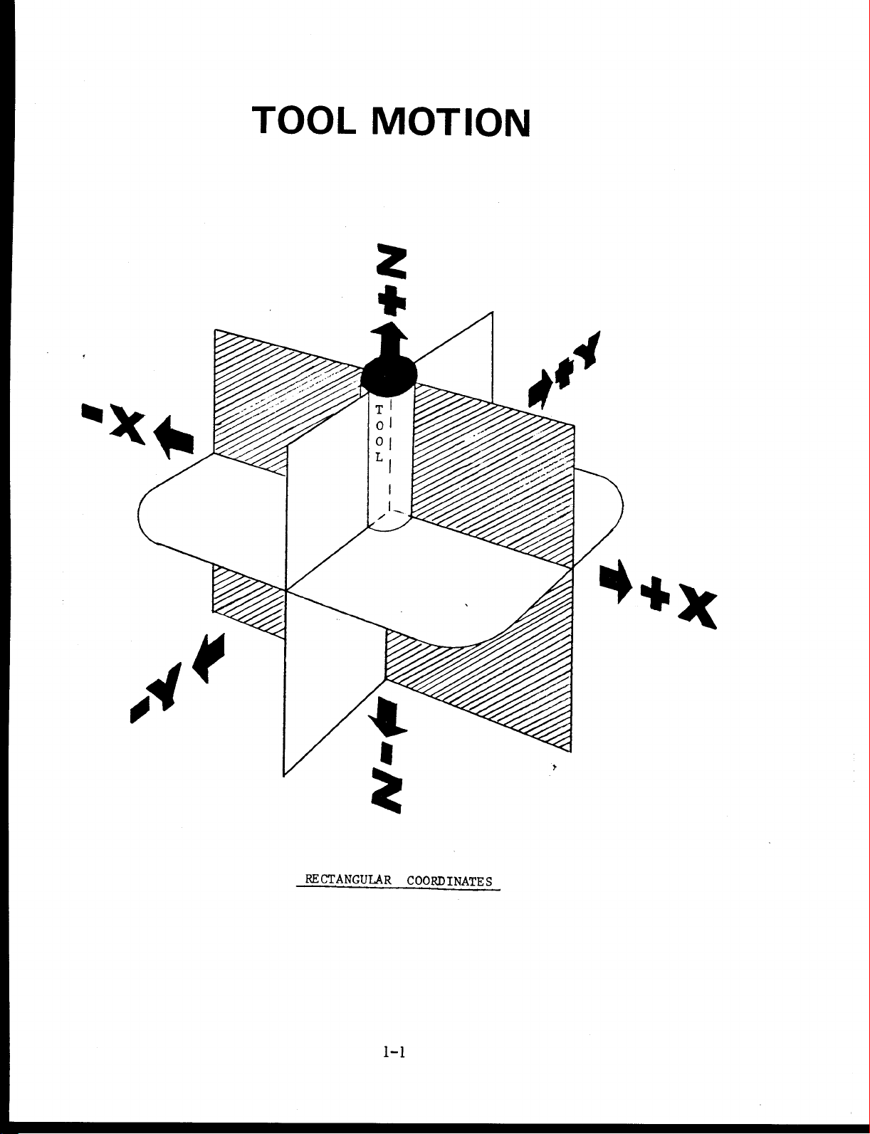
TOOL
MOTION
s*
*
m
mm
i
*
I
4
m
**
m
RECTANGULAR
1-1
COORDINATE
S
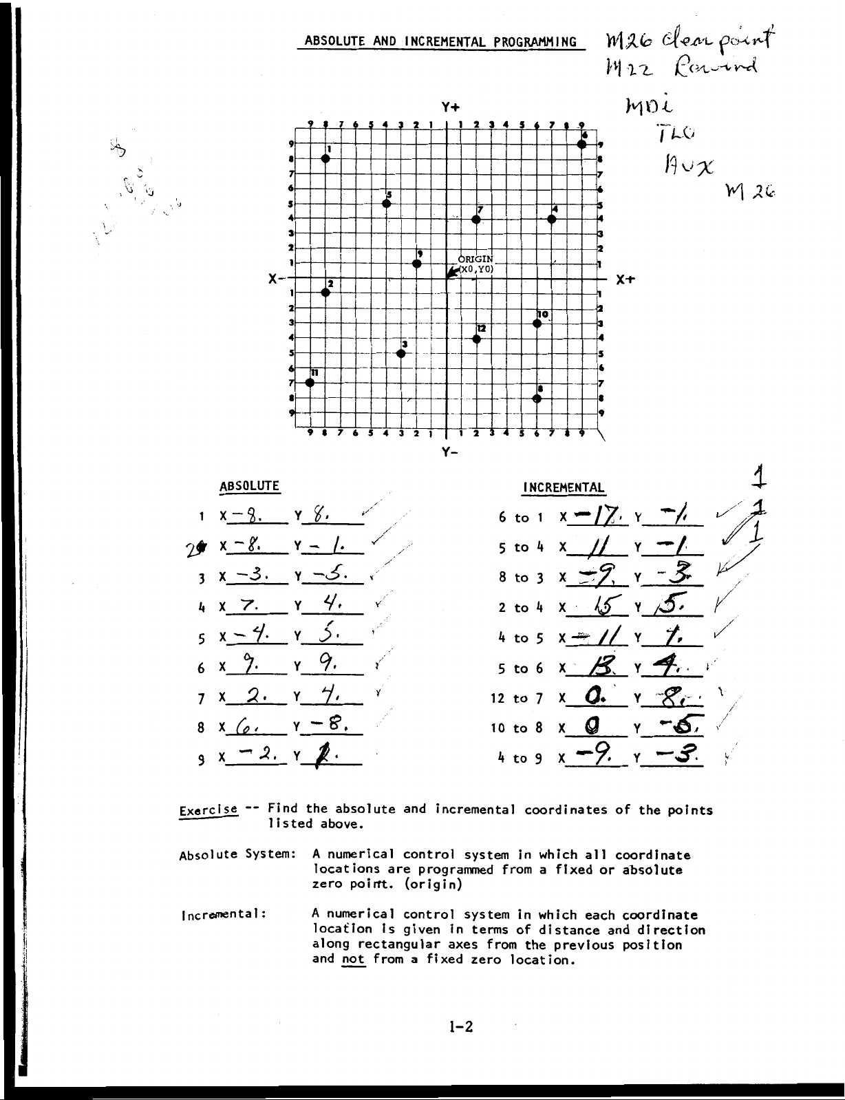
ABSOLUTE
AND
INCREMENTAL
PROGRAMMING
\A9Jc
}'v|
I'L
4
'(’-A'L
X-
ABSOLUTE
4b
Y+
9
7
I
u
2
o
n
9
7
4
i
3
1
7
4
it
2
1
7
it
ORIGIN
<(XO,YO)
4b
9
«
<
-9
4
J
4
x+
10
«
3
6
4
3
--ib
2
1
2
Y-
ib
a
ib
T
6
INCREMENTAL
MO
-l
yu
o
VI
i
-
j.
X
1
X-Zh—
2#
-3.
x
3
5
7.
x
X-V.
x_i
x
a.
Y
x
4
X
—
System:
i,
6
7
8
9
Exercise
Absolute
Incremental
jj,
Find
listed
:
Y
y
~
Y
_
Y
Y
>
Y
Y
*“
Y
Yÿ
the
A
locations
zero
A
location
along
and
/ÿ
V:
9.
y.
f?.
absolute
above.
numerical
poirft.
numerical
rectangular
not
,
Y
i
y
from
are
is
and
control
(origin)
control
given
incremental
system
programmed
system
in
axes
a
fixed
terms
from
zero
6
5
8
2
4
5
12
to
10
to
4
to
from
location.
to
to
to
to
to
to
in
in
of
1
X
4
x_ÿ2_
3
4
X
5
6
X
x
7
a*
8
_n2_
x
9
coordinates
which
a
which
distance
the
all
fixed
each
previous
n>
[J
kS'
//
or
and
v
Y
-/
Y
Y
S-
Y
£
Y
V
ffV
y
Y_mÿ.
of
coordinate
absolute
coordinate
position
points
the
direction
1/
i
\
/
V
1-2
&
z{0>
%
o
c-vC'h'i*'
yÿycÿvw—
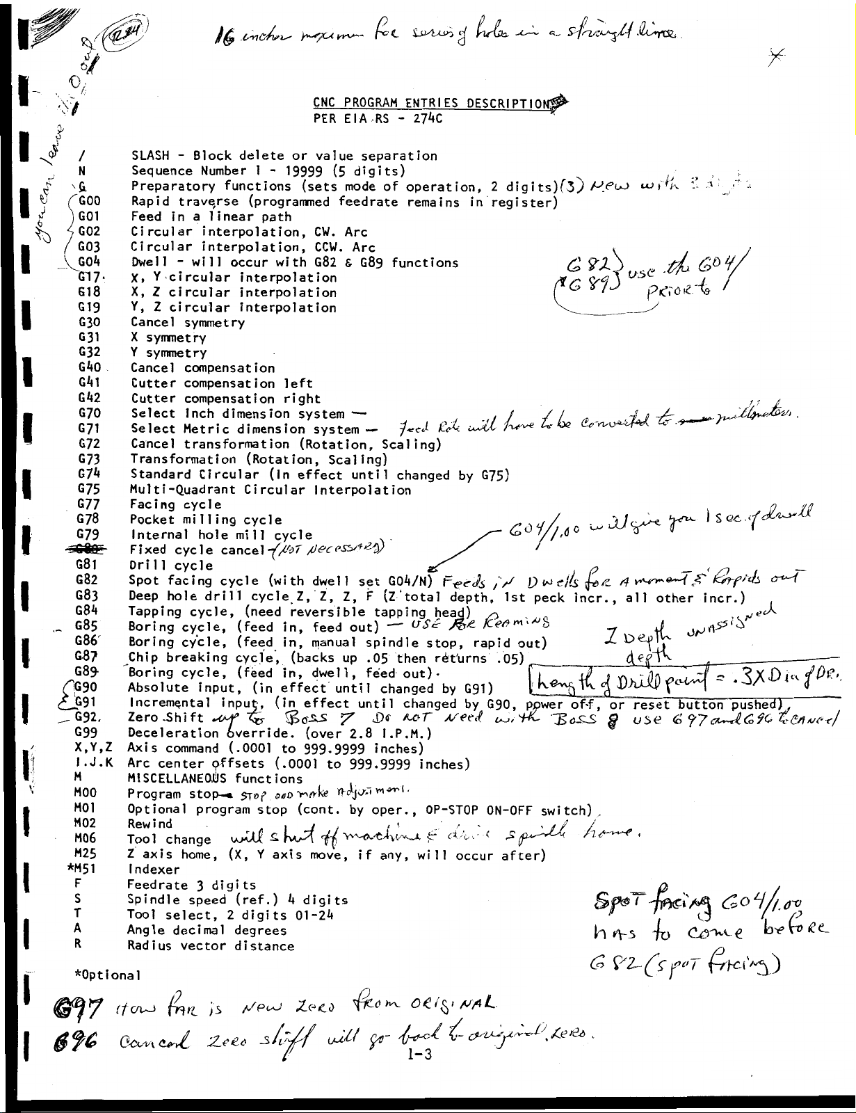
CNC
PER
a
PROGRAM
RS
EIA
-
ENTRIES
nkZ
Irlrbh.
ej
DESCRIPTIO
s
.HL*YC&
X
£
i
V
/
N
a
GOO
G01
G02
G03
XGOi»
GT7-
G
8
1
G19
G30
G31
G32
G40
G41
GA2
G70
G71
G72
G73
G7ÿ
G75
G77
G78
G79
G8l
G82
G83
G8A
G85
G86
G87
G8ÿ
(f;G90
<tp9i
G92.
G99
X,Y,Z
I.J.K
M
MOO
M01
M02
M06
M25
*M51
F
s
T
A
R
*0ptional
SLASH
Sequence
Preparatory
Rapid
Feed
Circular
Circular
Dwell
X,
X,
Y,
Cancel
X
symmetry
Y
symmetry
Cancel
Cutter
Cutter
Select
Select
Cancel
Transformation
Standard
Multi-Quadrant
Facing
Pocket
Internal
Fixed
Drill
Spot
Deep
Tapping
Boring
Boring
Chip
Boring
Absolute
Incremental
Zero
Deceleration
Axis
Arc
MISCELLANEOUS
Program
Optional
Rewind
Tool
Z
axis
I
ndexer
Feedrate
Spindle
Tool
Angle
Radius
Block
-
Number
traverse
a
n
i
interpolation,
interpolation,
-will
Y
circular
Z
circular
Z
circular
symmetry
compensation
compensation
compensation
Inch
Metric
transformation
Circular
cycle
milling
hole
cycle
cycle
facing
hole
cycle,
cycle,
cycle,
breaking
cycle,
input,
ft
-Shi
command
center
stop-«
program
change
home,
3
speed
select,
decimal
vector
functions
near
1
i
occur
dimension
cancel
cycle
drill
i
npu
override,
(.0001
offsets
(X,
digits
2
1
path
(In
(with
cycle
(in
stop
£
Y
or
-
19999
with
left
right
system
effect
cycle
Z, Z,
reversible
In,
in,
(backs
in,
effect
(in
to
(.0001
(cont.
XX
axis
*4
01-2A
delete
(programmed
interpolation
interpolation
interpolation
dimension
(Rotation,
Circular
cycle
mill
(need
(feed
(feed
cycle,
(feed
Jt,
functions
570ÿ
(ref.)
digits
degrees
distance
value
(5
(sets
(Rotation,
mode
feedrate
CW.
Arc
CCW.
Arc
G82
6
system
Scaling)
until
Interpolation
dwell
Z,
out)
feed
manual
up
dwell,
until
effect
(over
2.8
999-9999
to
999-9999
by
Y*'ÿeivi/vu.
move,
digits
separation
digits)
of
functions
G89
—
—
Scaling)
.
GOA/N)
set
(Ztotal
F
tapping
—
spindle
then
.05
feed
changed
until
I.P.M.)
inches)
oper.,
any,
if
operation,
remains
keÿ<-
•J-eeS
changed
F*><rJs
depth,
head)
O
Sc
stop,
returns
out)-
by
changed
kto
inches)
•
0P-ST0P
4r
will
occur
2
register)
in
G75)
by
/
—
,V
Kerf™'
rapid
.05)
G91)
by
G90,
0N-0FF
f
after)
ts)f3.)
digi
&
c>
c
be
/*.-
p
c/&
1st
peck
incr.,
,
b
out)
power
S
QUZJX
of-f,
switch),
?l)>
3
vf
p
/Z
St
fe
1
or
H
*V3
(s>
.
'K
i
-•
-
US<?
pic’ro-e
/
"X-
-
e-~
{
JC
all
other
vA.
reset
uSt?
button
(o
•
~fo
yt>T
,
'
X
incr.)
Z
'
‘X
55
pushed),
Co
(T>
€
(L
@*ÿ7
0
Octsn
fh'l
(V>/
/3
ZxCc
!J9lÿ
_s
Zeco
0
K
oetÿi
vfiL
1-3
TOOL
LENGTH
OFFSET
(TLO)
III
Work
L
Piece
T
TLO
Nr
Value
"Z"
II
Home
II
7
Zero
Table
(
Quill
fully
retracted)
Tool
Tool
Length
Length
Offset:
Offset
Value:
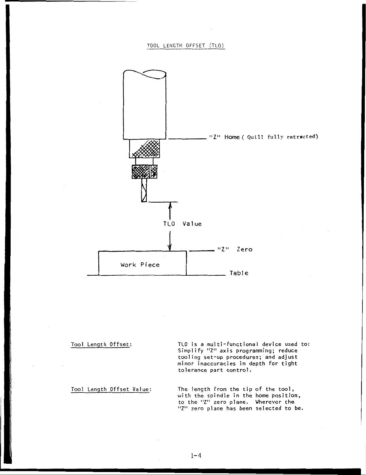
TLO
is
Simplify
tooling
minor
tolerance
length
The
with
the
to
"Z"
zero
1-4
a
multi-functional
"Z"
set-up
inaccuracies
part
from
spindle
the
zero
"Z"
plane
programming;
axis
procedures;
control.
the
in
plane.
has
in
tip
the
been
depth
of
home
Wherever
selected
device
and
for
the
position,
used
reduce
adjust
tight
tool,
the
to
to:
be.
G92
FLOATING
ZERO
SHIFT
I
G92
X,Y,Z
#1
is
G92
below.
for
you
NOTE
MDI
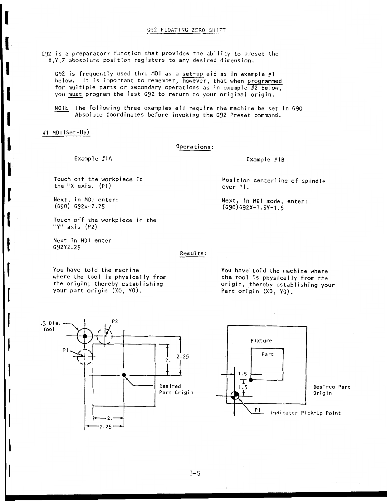
Touch
the
Next,
(G90)
Touch
"Y"
a
preparatory
abosolute
frequently
is
It
multiple
t
mus
The
Absolute
(Set-Up)
Example
off
"X
axis.
in
G92x-2.25
off
axis
is
program
following
the
MDI
the
(P2)
function
position
used
important
parts
the
Coordinates
#1A
workpiece
(PI)
enter:
workpiece
or
last
three
that
registers
MDI
thru
to
remember,
secondary
G92
examples
before
in
the
in
provides
to
as
operations
to
return
invoking
the
any
desired
a
set-up
however,
to
require
all
Operations:
ability
aid
as
your
the
to
dimension.
as
in
that
when
example
in
original
the
machine
Preset
G92
Position
over
PI
Next,
(G90)G92X-1
preset
example
programmed
#2
below,
origin.
be
command.
Example
centerline
.
In
MDI
.5Y-1
the
#1
set
#1B
mode,
.5
in
G90
of
enter:
spindle
I
I
I
I
I
.5
Dia
Tool
Next
in
G92Y2.25
You
have
where
the
your
the
origin;
part
PI
MDI
told
V.
enter
tool
thereby
origin
\
the
/
2.25
is
u
2.
P2
r
machine
physically
establishing
YO)
(XO,
Resul
from
.
"M
2.25
•
l
red
Des
i
Origin
Part
:
ts
You
have
told
the
the
origin,
Part
tool
origin
1-5
1.5
is
physically
thereby
(XO,
Fixture
Part
IL
machine
establishing
YO)
.
Indicator
where
from
Des
Origin
Pick-Up
the
your
i
red
Point
Part
1-5
Floating
G92
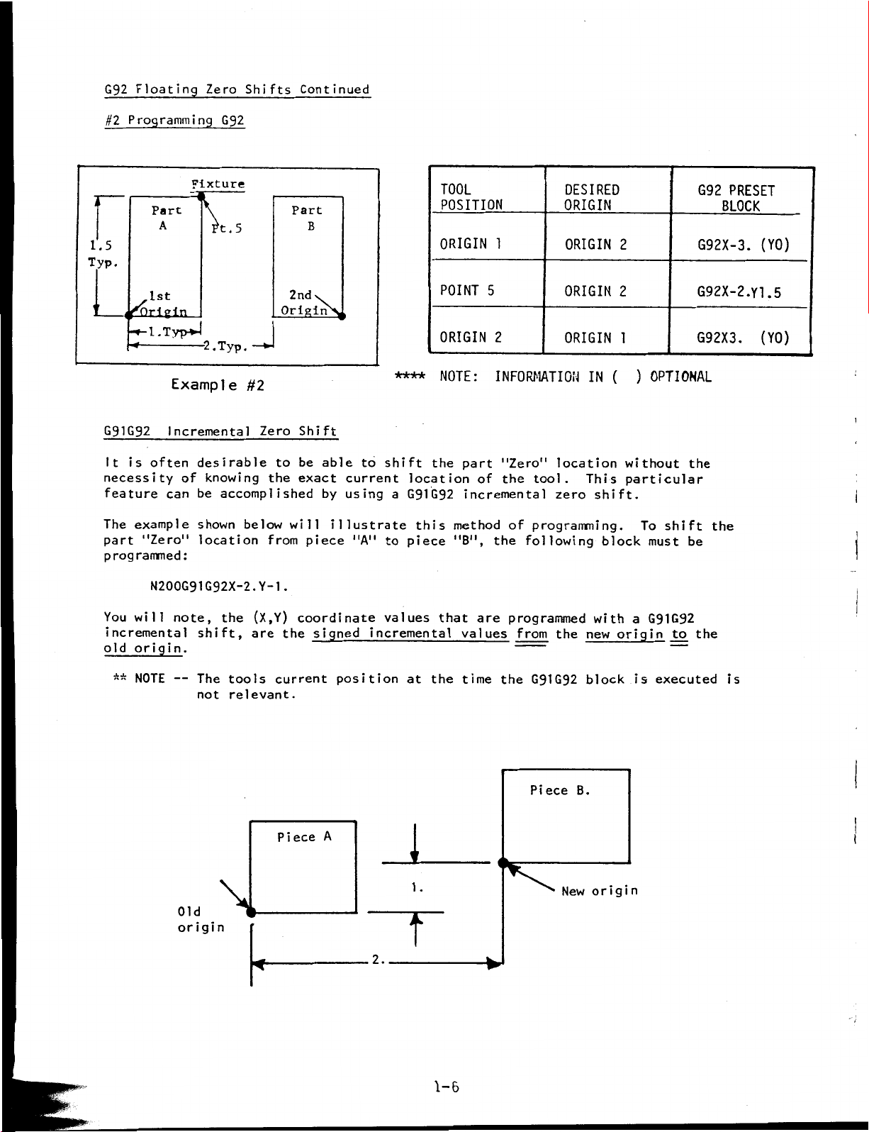
Programming
#2
Zero
G92
Shifts
Continued
1.5
Typ.
G91G92
is
It
necessity
feature
example
The
part
programmed:
Fixture
Part
A
1st
\
5
t.
l.Typ-*4
Typ.
-2.
Example
Incremental
often
can
"Zero"
desirable
of
be
shown
location
#2
knowing
accomplished
below
Zero
the
from
N200G91G92X-2.Y-1
Part
B
2nd
Originÿ,
Shift
be
to
exact
will
piece
.
v
able
by
illustrate
to
current
using
"A"
****
shift
location
a
G91G92
piece
to
TOOL
POSITION
ORIGIN
POINT
ORIGIN
NOTE:
the
this
1
5
2
INFORMATION
part
"Zero"
of
the
incremental
method
the
"B",
tool.
of
programming.
following
DESIRED
ORIGIN
ORIGIN
ORIGIN
ORIGIN
IN
location
This
shift.
zero
2
2
1
(
block
)
OPTIONAL
without
particular
To
shift
must
G92
PRESET
BLOCK
G92X-3.
(YO)
G92X-2.YI.5
G92X3.
the
the
be
(YO)
You
will
incremental
origin.
old
NOTE
**
note,
--
Old
origin
shift,
The
not
the
tools
relevant.
\l
(X,Y)
are
coordinate
the
current
Piece
signed
position
A
values
incremental
the
at
1
1
.
T
2.
that
are
values
time
programmed
from
the
the
G91G92
Piece
New
B.
with
new
block
origin
a
origin
is
G91G92
to
executed
the
is
1-6
GUTDE
TO
I
AND
J
USAGE
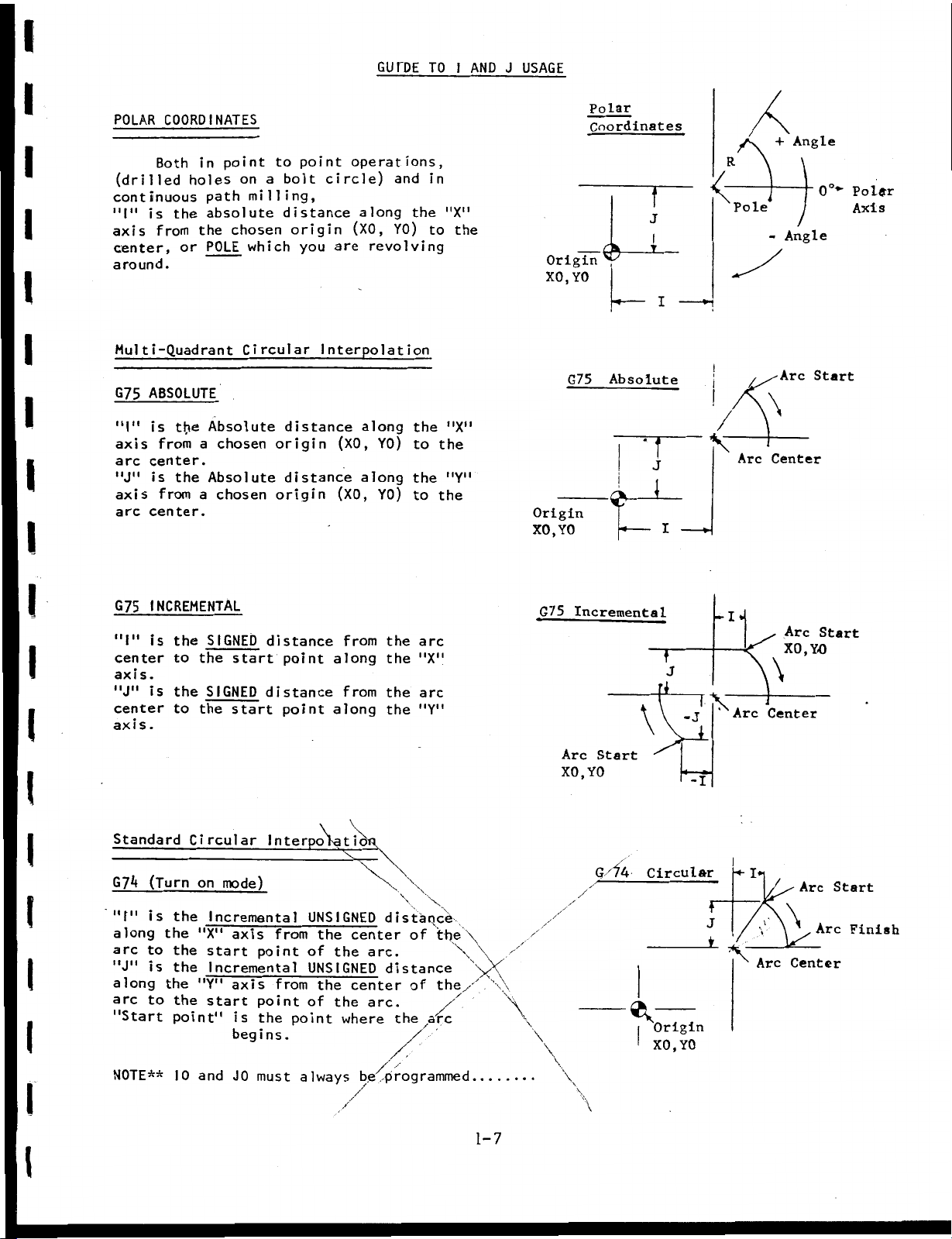
POLAR
(drilled
continuous
"I"
axis
center,
around.
COORDINATES
in
Both
holes
path
the
or
absolute
the
POLE
is
from
Multi-Quadrant
ABSOLUTE
G75
is
"I"
axis
arc
"J"
axis
arc
the
from
center.
is
the
from
center.
Absolute
a
Absolute
a
point
on
milling,
chosen
which
Circular
chosen
chosen
to
bolt
a
distance
origin
distance
origin
distance
origin
point
circle)
you
are
Interpolation
(XO,
(XO,
operations,
and
along
(XO,
YO)
revolving
along
YO)
along
YO)
the
the
to
the
to
Polar
Coordinates
in
"X"
the
to
Origin
YO
XO,
G75
T
J
I
T
I
Absolute
Z
i
+
-
Angle
Angle
Arc
0°~
Start
Polgfr
Axis
\
"X"
the
"Y"
the
Origin
XO,
YO
'
J
Arc
Center
i
I
INCREMENTAL
G75
"I"
is
center
axis.
"J"
is
center
axis.
Standard
(Turn
G7*<
II
pi
is
along
arc
to
"J"
is
along
arc
to
"Start
NOTE**
the
to
the
to
Circular
the
the
the
the
the
the
point"
10
S
GNED
I
start
the
SIGNED
the
start
mode)
on
Incremental
"X"
axis
start
point
Incremental
"Y"
axis
start
point
is
begins.
and
JO
must
distance
point
distance
point
Interpolat
from
from
point
the
always
from
along
from
along
ioi
UNSIGNED
the
center
of
UNSIGNED
the
of
the
center
the
where
arc.
arc.
beÿprogrammed
the
arc
the
"X"
the
arc
"Y"
the
distaqcd
of
distance
of
a
the
/
the
the
're
G75
Incrementa
1
T
j
1
-
*
Arc
XO,
Start
YO
i
Arc
-J
Center
\
Arc
Start
XO,
YO
G'lh
/
V
/
\
\
\
\
\
\
u
Circular
Origin
YO
XO,
!ÿ
K
Arc
Start
f
J
Arc
Arc
Center
Finish
1-7
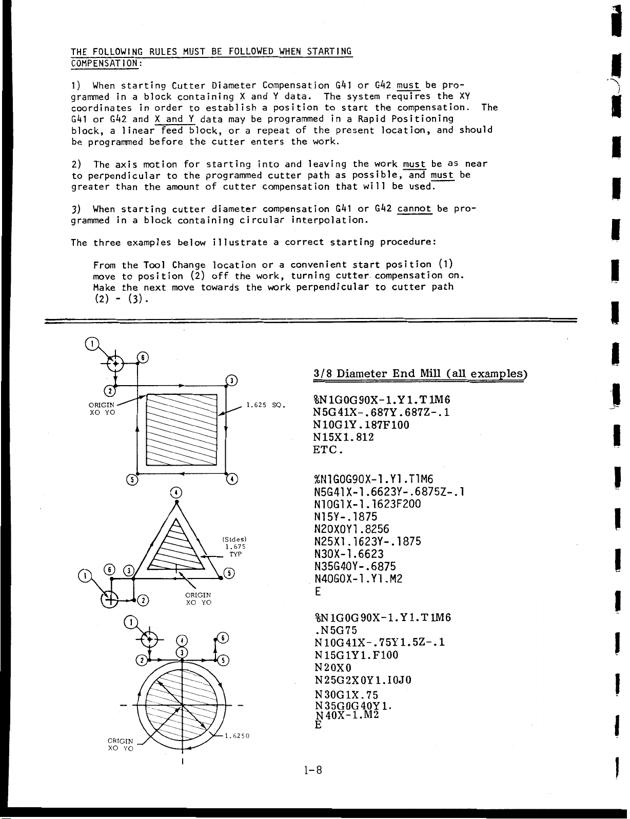
FOLLOWING
THE
COMPENSATION:
1)
grammed
coordinates
G41
block,
programmed
be
2)
perpendicular
to
greater
3)
grammed
The
When
G
or
a
The
When
three
starting
a
in
in
andXand
k2
linear
axis
than
starting
a
in
examples
RULES
block
order
feed
before
motion
the
block
MUST
Cutter
containing
to
Y
block,
for
the
to
amount
cutter
containing
below
BE
Diameter
establish
data
the
cutter
starting
programmed
of
diameter
illustrate
FOLLOWED
X
and
may
be
a
repeat
or
enters
into
cutter
circular
STARTING
WHEN
Compensation
Y
data.
position
a
programmed
of
the
work.
the
leaving
and
cutter
compensation
compensation
a
path
interpolation.
correct
G4l
The
to
start
in
present
as
that
G4l
starting
or
system
Rapid
a
the
possible,
will
or
G42
must
requires
compensation.
the
Positioning
location,
work
must
and
be
used.
G42
cannot
procedure:
be
the
and
be
must
be
pro¬
as
XY
should
near
be
pro¬
1
I
/
The
1
I
I
I
From
move
Make
(2)
1
ORIGIN
XO
\
the
to
the
-
cK®
at
YO
©
ORIGIN
XO
(3).
®,
1
YO
Tool
position
next
'©
2
Change
(2)
move
CD
\
ORIGIN
XO
4
i
location
off
towards
J®
ID
(Sides)
1.675
YO
f
%
1.6250
TYP
the
the
1
.625
or
work,
work
SO.
a
convenient
turning
perpendicular
3/8
%N
N5G41X-.
N10G1Y.187F100
N
ETC.
%N1G0G90X-1.Y1
N5G41X-1
N10G1
N15Y-.1875
N20X0Y1
N25X1
N30X-1
N35G40Y-.6875
N40G0X-1.Y1.M2
N
N15G1Y1.F100
N2OX0
N25G2X0Y1.I0J0
N30G1X.75
N35G0G40Y1.
E
1-8
start
cutter
Diameter
1G0G90X-1.Y1.T
15X1.
compensation
to
687Y.687Z-.
812
.6623Y-.6875Z-.1
1623F200
X-l
.
.8256
.1623Y-.1875
.6623
E
1G0G90X-1.
%N
.N5G75
10G41X-
75Y1.
.
N40X-1.M2
position
cutter
End
.T1M6
Yl.T
Mill
5Z-
(1)
path
1M6
1M6
1
.
on.
(all
1
I
I
I
examples)
I
I
I
\
|
I
I
I
I
I
I
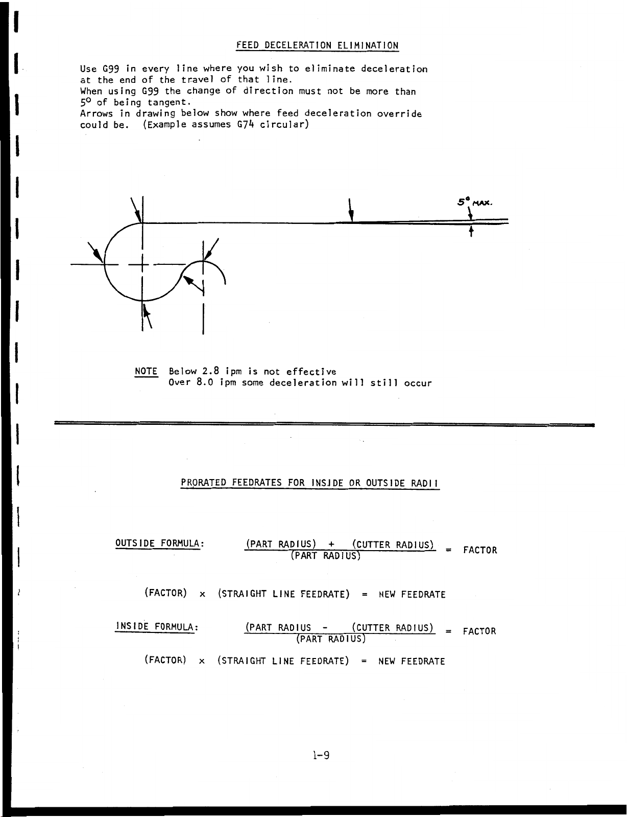
FEED
DECELERATION
ELIMINATION
I
I
I
I
I
I
I
Use
the
at
When
of
5°
Arrows
could
\
G99
using
being
be.
in
end
in
\
every
of
the
G99
tangent.
drawing
(Example
\
NOTE
line
the
below
N
Below
Over
travel
change
assumes
1/
8.0
where
show
2.8
of
of
ipm
ipm
you
wish
that
direction
where
circular)
G7*4
is
some
to
line.
must
feed
not
effective
deceleration
eliminate
not
be
deceleration
\
will
deceleration
more
than
override
still
occur
5°
MAX.
V
t
PRORATED
OUTSIDE
t
INSIDE
FORMULA:
(FACTOR)
FORMULA:
(FACTOR)
x
x
FEEDRATES
(PART
(STRAIGHT
(PART
(STRAIGHT
FOR
RADIUS)
(PART
FEEDRATE)
LINE
RADIUS
(PART
FEEDRATE)
LINE
I
NS
J
+
RADIUS)
RADIUS)
1-9
DE
OR
OUTSIDE
(CUTTER
=
NEW
(CUTTER
=
NEW
RADII
RADIUS)
FEEDRATE
RADIUS)
FEEDRATE
=
FACTOR
FACTOR
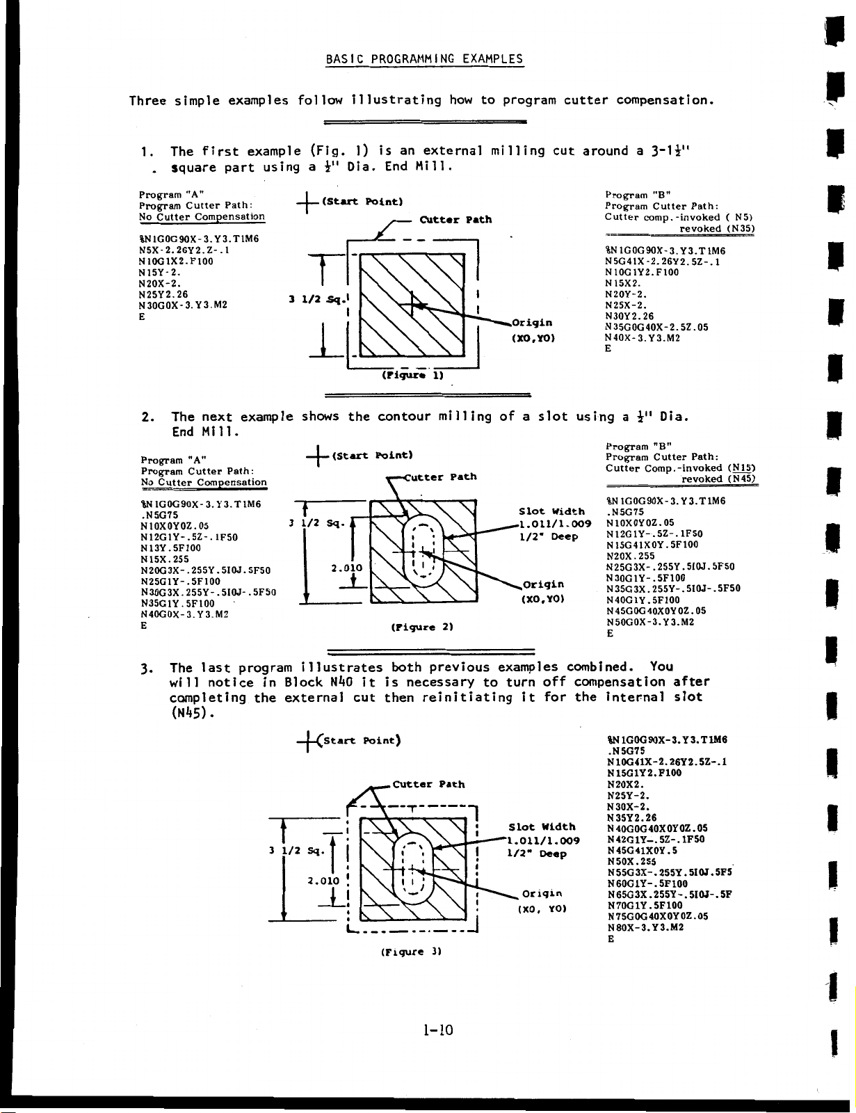
BASIC
PROGRAMMING
i
EXAMPLES
Three
simple
The
1.
square
.
Program
Program
No
%N
N5X-2.26Y2.Z-.1
N10G1X2.F100
N15Y-2.
N20X-2.
N25Y2.26
N30G0X-3.
E
2.
Program
Program
No
%N
.N5G75
N
N12G1Y-.5Z-.1F50
N13Y.5F100
N15X.255
N20G3X-
N25G1Y-
N30G3X
N35G1Y
N40G0X-3.
E
"A”
Cutter
Cutter
1G0G9OX-
The
End
"A"
Cutter
Cutter
1G0G90X-
10X0Y0Z
.
.
.
255Y-.5I0J-.5F50
.
5F100
examples
first
part
Path:
Compensation
3.
Y3.T
Y3.M2
next
Mill.
Path:
Compensation
T
3.
Y3.
.
05
5I0J.
255Y.
5F100
Y3.M2
example
using
1M6
example
1M6
5F50
follow
+
3
1/2
shows
T
3
1/2
(Fig.
a
(Start
T
1
—
iH
SqJ
(Start
Sq.
2.010
illustrating
1)
is
End
Dia.
Point)
(Figure
the
contour
Point)
X
(Figure
an
Mill.
Gutter
l
1
V
how
external
Cutter
1)
milling
Path
\
,1
,
I
.
2)
Path
I
l
to
milling
program
Origin
(XO,YO)
of
a
Slot
.1.011/1.009
1/2-
Origin
(XO,
slot
Y0)
cutter
cut
Width
Deep
compensation.
around
using
a
3~1i"
Program
Program
Cutter
%N1GOG90X-3.Y3.T1M6
N5G41X-2.26Y2.5Z-.1
N10G1Y2.F100
N
N20Y-2.
N25X-2.
N30Y2.26
N
N40X-3.Y3.M2
E
Program
Program
Cutter
%N
.N5G75
N10X0Y0Z.05
N12G1Y-.5Z-.1F50
N
N20X.255
N25G3XN30G1Y-.5F100
N35G
N40G1Y.5F100
N
N50G0X-3.
E
"B"
Cutter
__
comp.
15X2.
35G0G40X-2.
Dia.
a
iH
"B”
Cutter
Comp.
1G0G90X-
15G41X0Y
.255Y.5I0J.5F50
3X
255Y-.
.
45GOG40X0Y
Y3.M2
-invoked
revoked
5Z
-invoked
revoked
3.
Y3.T
.
5F100
0Z.05
Path:
.
Path:
5I0J-
05
1M6
.
(
(N35)
(N15)
(N45)
5F50
N5)
P
P
i
I
V
I
i
I
I
I
3.
last
The
notice
will
completing
(N45).
program
in
the
3
illustrates
Block
external
(start
|—
—
\
Sq.
1/2
2.010
HkO
J_!
«
I
:
4
it
cut
Point)
both
is
then
Cutter
v;
(Figure
previous
necessary
reinitiating
Path
3)
1-10
i
to
t
I
I
«
i
i
examples
off
turn
it
Width
Slot
1.011/1.009
Deep
1/2"
Origin
(X0,
combined.
compensation
for
the
YO)
You
after
255Y
.
255Y-
.
Y3.M2
slot
Y3.T1M6
5
5I0J
.
5IQJ-
.
internal
%N
1G0G90X-3.
.N5G75
N10G41X-2.26Y2.5Z-.
N15G1Y2.F100
N20X2.
N25Y-2.
N30X-2.
N35Y2.26
N4OGOG40X0Y0Z.05
N42G1Y-.5Z-.1F50
N45G41X0Y.
N50X.255
N55G3X-
N60G1Y-.5F100
N65G3X
N70G1Y.5F100
N75G0G40X0Y0Z.05
N80X-3.
E
.
1
5F5
5F
.
I
i
I
I
I
I
I
I
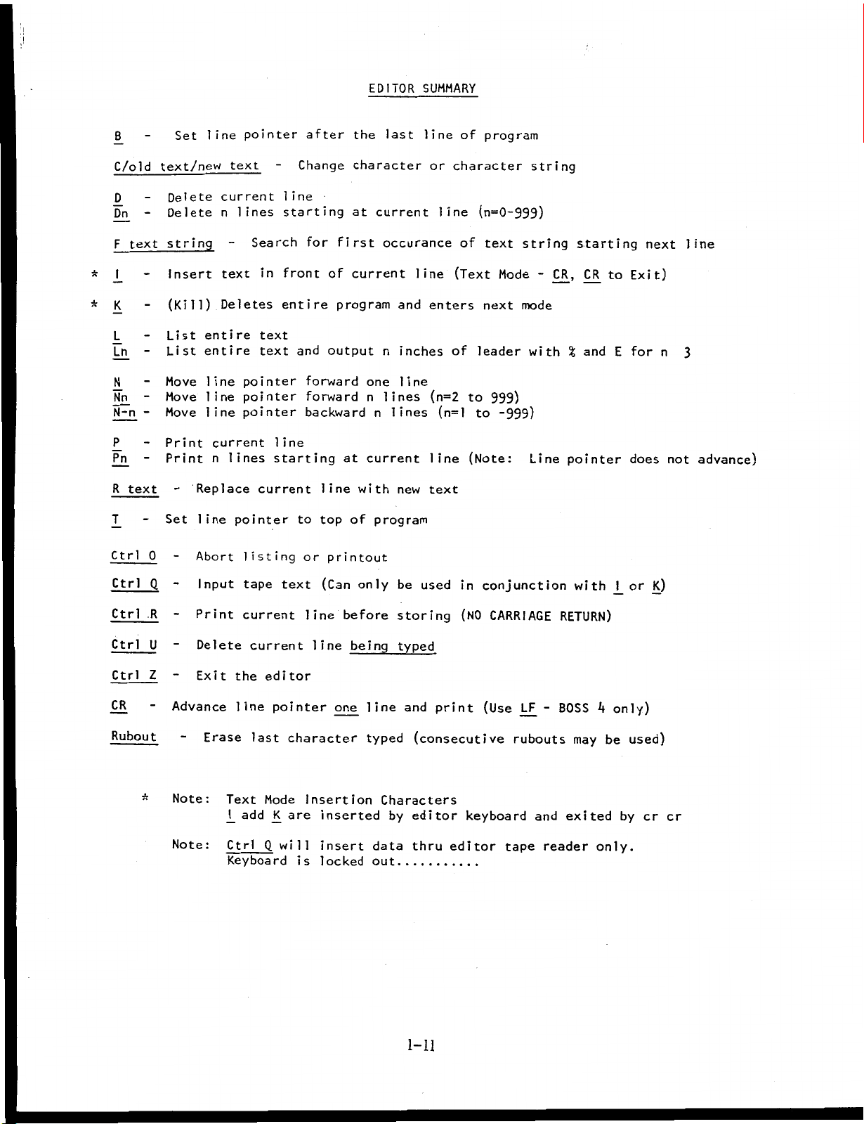
EDITOR
SUMMARY
*
*
B
C/old
D
Dn
F
text
I
K
L
Ln
N
Nn
N-n
P
Pn
R
text
T
Set
text/new
Delete
Delete
string
Insert
(Kill)
entire
List
entire
List
Move
line
Move
line
Move
Print
Print
Replace
line
Set
line
current
n
text
Deletes
line
current
n
pointer
text
lines
pointer
pointer
pointer
lines
pointer
Search
in
text
text
line
starting
current
after
Change
the
character
line
starting
for
front
entire
and
at
first
of
current
program
output
forward
forward
backwardnlines
at
line
with
top
to
of
last
current
occurance
and
n
inches
line
one
lines
n
current
new
program
line
line
or
line
enters
(n=2
(n=l
line
text
of
program
character
(n=0-999)
of
text
(Text
next
of
leader
999)
to
to
(Note:
Mode
-999)
string
string
-
mode
with
Line
CR,
%
pointer
starting
CR
to
and
E
next
Exit)
for
does
n
not
line
3
advance)
Ctrl
Ctrl
Ctrl
Ctrl
Ctrl
CR
Rubout
*
0
Q
R
U
Z
Abort
Input
Print
Delete
Exit
Advance
Erase
:
Note
:
Note
listing
tape
current
current
the
editor
line
last
Text
Mode
add
J_
Ctrl
Q,
Keyboard
text
pointer
character
K
are
will
is
printout
or
(Can
line
before
line
one
Insertion
inserted
insert
locked
only
being
line
typed
be
storing
typed
and
(consecutive
Characters
by
editor
data
thru
out
used
print
in
(NO
keyboard
editor
conjunction
CARRIAGE
(Use
LF
rubouts
and
tape
with
RETURN)
BOSS
-
may
exited
reader
J_
only)
4
be
only.
or
used)
by
cr
J<)
cr
1-11
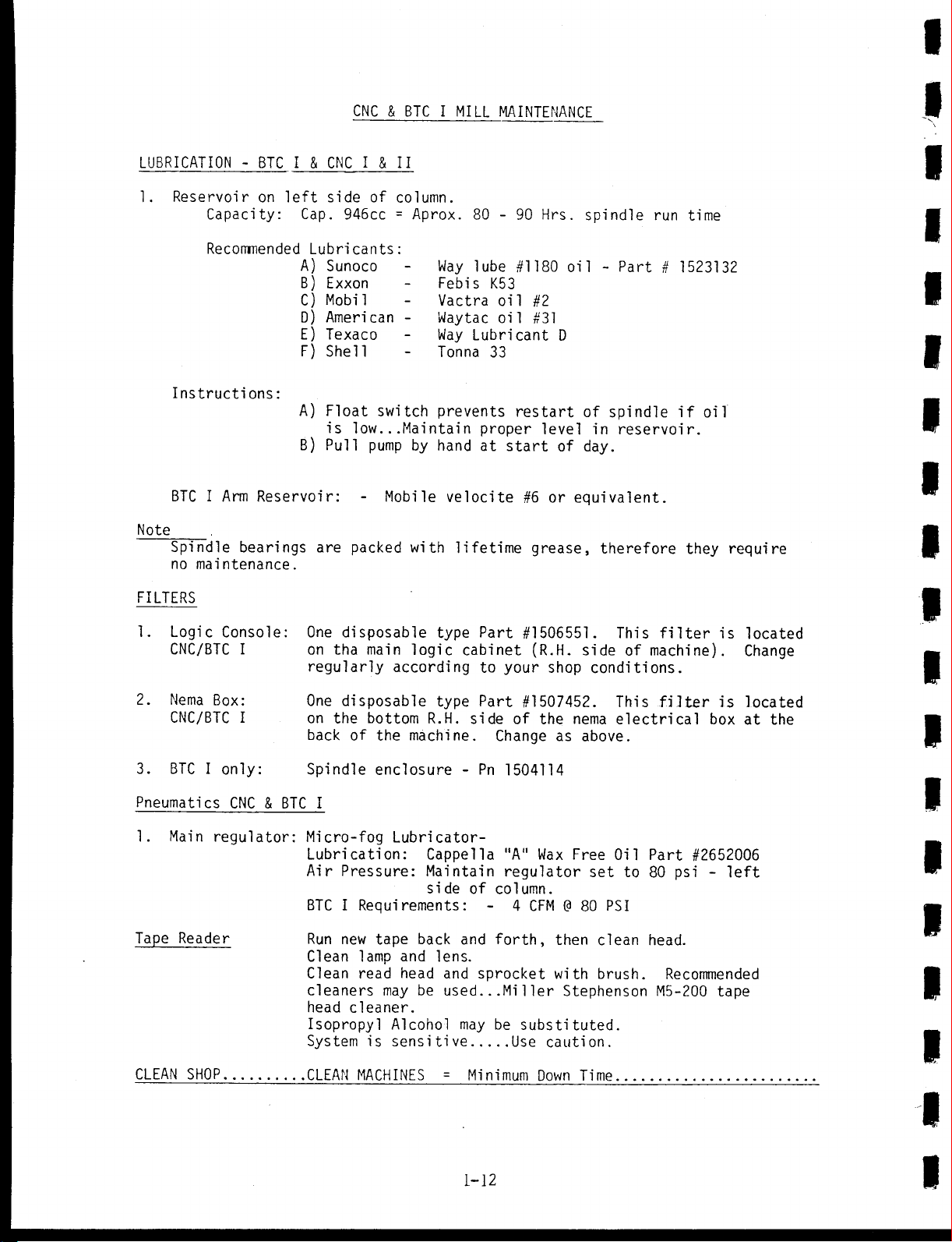
CNC
&
BTC
I
MILL
MAINTENANCE
I
I
LUBRICATION
1.
Reservoir
Capacity:
Recommended
Instruct!-
I
BTC
Note
Spindle
no
FILTERS
Logi
.
1
Arm
maintenance.
c
Console:
CNC/BTC
2.
Nema
Box:
CNC/BTC
3.
BTC
I
only:
BTC
-
on
ons
:
Reservoir:
bearings
I
I
CNC
I
&
side
left
Cap.
Lubricants:
A)
Sunoco
B)
Exxon
C)
Mobil
D)
American
E)
Texaco
F)
Shell
A)
Float
is
B)
Pull
are
One
on
regularly
One
on
back
Spindle
I
&
of
946cc
switch
low...Mai
pump
Mobile
packed
disposable
main
tha
disposable
the
bottom
the
of
enclosure
II
column.
=
Aprox.
Way
Febis
Vactra
Waytac
-
Way
Tonna
prevents
ntain
by
hand
velocite
with
type
logic
according
type
R.H.
machine.
80
lube
K53
Lubricant
33
proper
at
lifetime
Part
cabinet
to
Part
side
Pn
-
90
-
#1180
oil
#2
oil
#31
restart
start
#6
grease,
#1506551.
(R.H.
your
#1507452.
of
Change
1504114
Hrs.
oil
D
level
of
or
shop
the
as
spindle
Part
-
of
spindle
in
reservoir.
day.
equivalent.
therefore
This
side
of
conditions.
This
nema
electrical
above.
run
time
1523132
#
if
oil
they
filter
machine).
filter
is
is
box
require
located
Change
located
at
I
I
I
I
1
I
I
I
I
the
R
Pneumati
Main
1.
Tape
Reader
CLEAN
SHOP
cs
CNC
regulator:
&
BTC
I
Micro-fog
Lubrication:
Air
Pressure:
Requirements:
I
BTC
Run
Clean
Clean
cleaners
head
Isopropyl
System
CLEAN
tape
new
lamp
read
cleaner.
is
MACHINES
Lubricator-
Cappella
Maintain
side
back
and
lens.
head
may
be
Alcohol
sensitive
of
and
and
used...
may
=
Minimum
1-12
"A"
regulator
column.
4
forth,
sprocket
Mi
Her
be
substituted.
Use
Wax
@
CFM
then
with
Stephenson
caution.
Down
Free
set
80
Time
Oil
to
PSI
clean
brush.
Part
#2652006
psi
80
head.
Recommended
M5-200
-
left
tape
V
R
R
R
R
R
R
"U
J3
o
CD
m
1
C/5
m
H
PROBLEM
SET
Bridgeport
Machines
TEXTRON
DivisionofTextron
Inc.
I
I
I
I
I
I
I
I
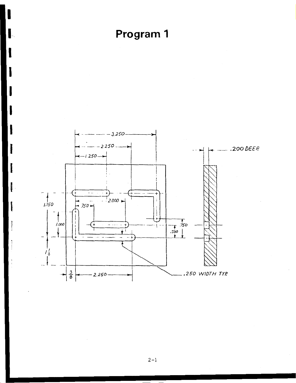
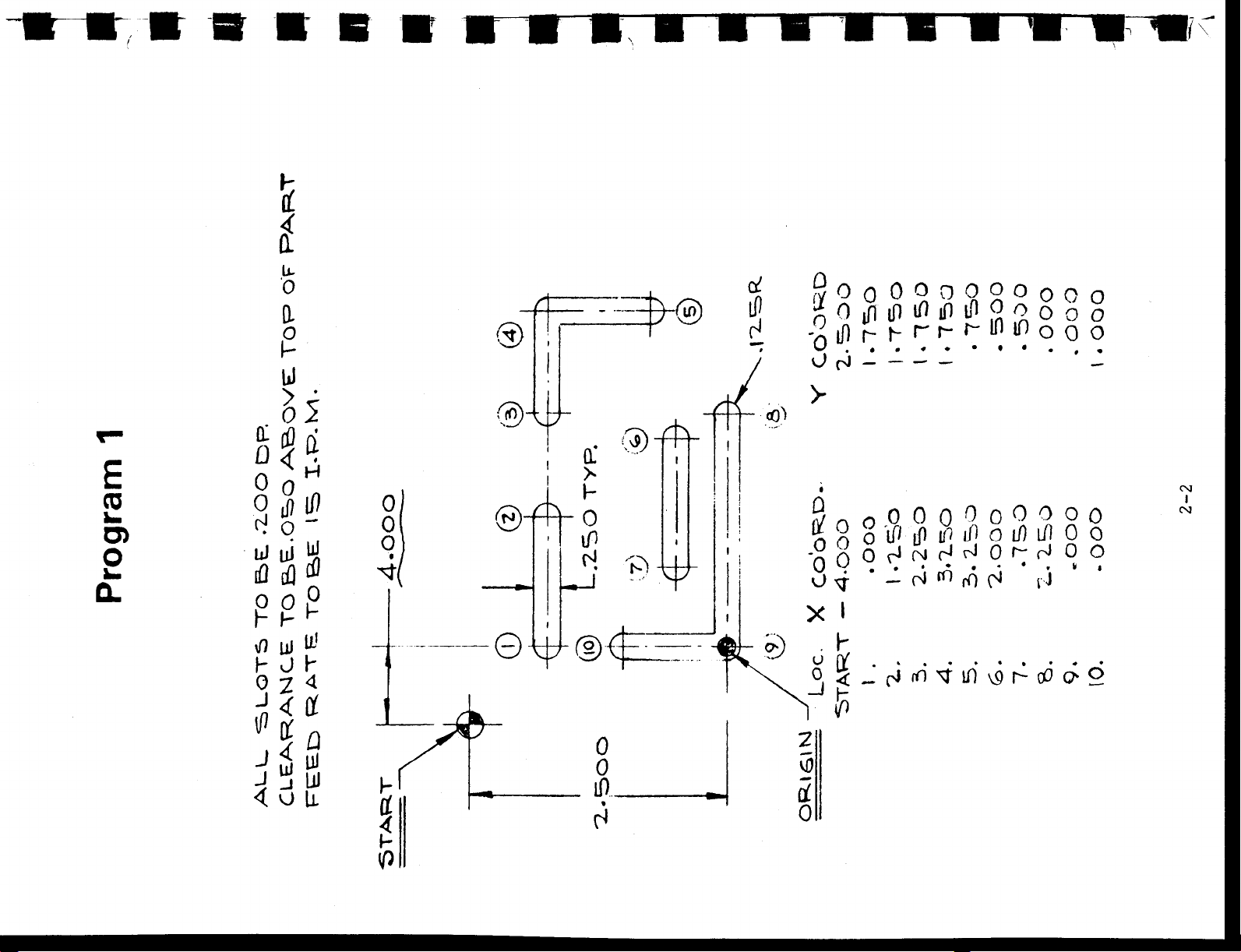
Program
3.2fO
-----
250
---
U—
1.250—
2
J
>-
---
l
~7)_
I
1.750
t
1.000
H
i
750
-G
-
H
I
!
-2.000
—
i
»J
i
{j
1
i>
1
>
R
.200
N
\
\K
\
x
-
i
f
.7
So
f
.500
i
1
\
\
N
\
\
DEE
>1
-J
3
8
2.2SO
2-1
.250
WIDTH
TYP
£
CD
o>
o
CL
m
m
o
o
r)
uJ
£
o
h
\f)
hJp
0
\
a
U
0
a
o
h
UJ
oi
o
jJlfl
-
o
y
ui
<0
ifl
P
o
h
i-
UJ
UJ
<
2
B
0
0
0
u
®
®\K
i
a-
h
0
iP
H.
2>
Kg)
®fh
d
l»
H
S>
JyOoOODQOOoGO
£Otfiniflinifl°gooo
vj
fO
-
>
s>
Q
,„o0000000O0
o
xq-
I
h
iP
o
S
SoOrJNHHOr-rJOO
U
X
—
iP
_
—
—
$
iP
m
ol
1/]
ro
o
(\|
i/)
i/i
j
*
'
-I
c\j
CN
o
°
j
-J
J
<
$
jw
o
fl
ui
u.
h
5
h
IP
0
0
lO
r1
z
V0
0
(0
o
o
0
r
r
71
*n
n
13
r
N
>
2
p
H
o
p
m
m
(II
5
>.
H
pi
H
2
$
hjf
[dÿJ
UI
.
O
OOOQOOQJ)
f°:::n
brÿboO
o
O
(ji
>
fo
i
O'
H
X
©
0,
o
0
0
-0-
©
©
0
7}
--0
o
0
!
z
4
r*
o
o
o
t
(fl
H
>
JO
H
z
(T
T>
o
CO
f
Q)
3
ro
6'
in
>
(P
O
m
H
0
TJ
O
T>
0>
H
*0
r
i
i
i
ec1;::.
i/ioouitnogo
OOO-OOOOjQ
i
i
i
c°
o
0
©
SS
0
X
©
0
p
PP
m
*
CP
in
o
0
®
0
00
E
CD
O)
O
CL
Q
2
J
J
Of
$
2
U
J
0
0
h
h
DC
<c
K
IP
o
o
3
©r
©
z
0
a
0
-%*ÿ
o:
Q
x-y
0
0
I
0
N
NO
©
©
or
0
in
H
x
J
d
9
o?
V
©
w
©
a
jfoi/)o°iOoiniPo
Q
°
U
S82rt°°90
2
0
IÿOOcJOholO
N
I
I
>
a
UOOnOOoO
0
U
U
x
n
-1
it-
o
H
<
£
0
If)
o
•••ÿ<•«
•
NÿOiOfOrOpj
—
N
-'
<0
0
?
i
xr
u
o
h
N
0
<0
—
I
o
in
H
I
OO
0
r-
N
I
o
04
«
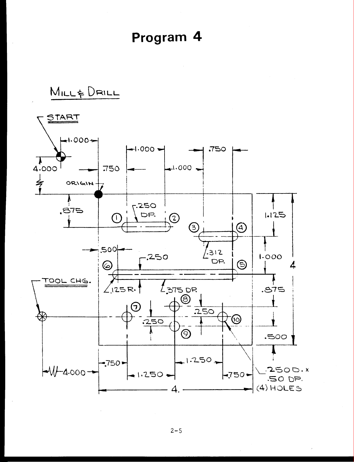
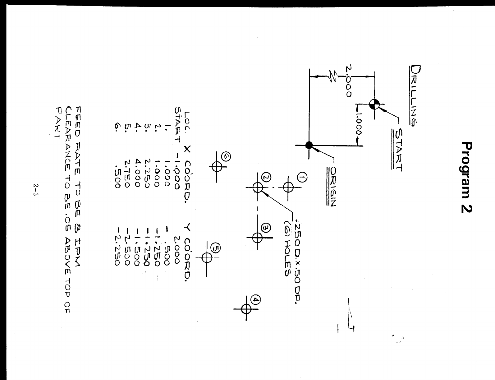
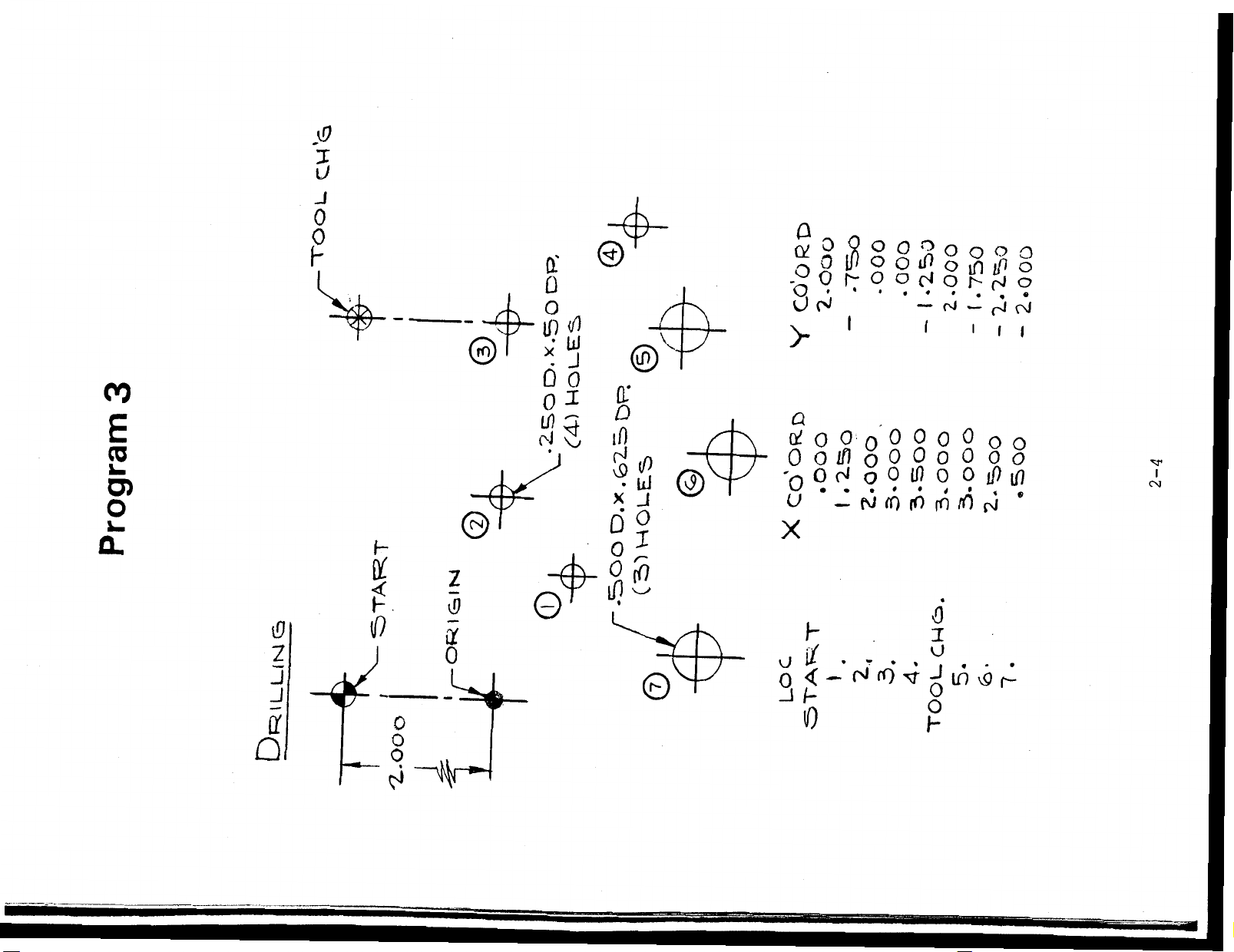
Program
4
i
MiLt_%
5
000
A.
TOOL
TART
-•ÿ1.000
I
,e>7=3
1
CHÿj.
DRILL
750
o
500
©
.125
R.
250
DP.
r
f
—
.1.000
k©
o
1
575
DR
.750
-*1
i
©
lÿ\-L
DP.
©
©
f
1.123
i
t
1-000
i
T
.e>7=>
4
!
-*M/-
4*000
--0--
-750
®
.250
-1250
©
I
I
O;
©
4.
2-5
J
.7.50
L
i
1-250
©
i
-750-
X
(4)
i
1
.500
4
i
.*30
HOLE
0.
DR.
5
x
 Loading...