


Vertical Machining Center
Operator’s Manual
DX32 CNC Control
October 1997
Code No. 1104-2832
Rev . A
®

COPYRIGHT 1997 BRIDGEPORT MACHINES, INC., ALL
RIGHTS RESERVED
This manual describes software that contains published and unpublished works of authorship
proprietary to Bridgeport Machines, Inc. It is made available for use and maintenance of our products.
Under copyright laws, this manual, or the software it describes may not be copied in whole, or in part,
without prior written consent of Bridgeport Machines, Inc., except in normal software use, as
described in the software license agreement.
The information in this document is subject to change without notice and should not be construed as a
commitment by Bridgeport Machines, Inc.
ii
/19960710
Changes from first edition (January 1996):
Updated Control Panel (Chapter 1)

iii
READ THIS FIRST!
Like most manufacturers, we go
to great lengths to make our
products as safe as possible—
but operators can still get hurt.
In virtually every case, the injury
is the result of:
■ Not knowing how to properly operate the machine;
■ Not following proper operating and safety procedures;
■ Carelessness or inattention;
■ Trying to “take a short cut;”
■ Poor maintenance.
For your personal safety, and to
get the maximum efficiency out
of this precision machine, read
and follow operation instructions
carefully.
Standard Safety Precautions for
operating the Vertical Machining
Center are:
■ NEVER operate machine without safety glasses.
■ DO NOT wear gloves,tie,scarf,ID bracelet,neck chain or
other object that could become entangled in the machine
or workpiece.
■ ALWAYS wait for the spindle to stop before bringing your
hands to the table or workpiece.
■ MAKE CERTAIN workpiece is SECURELY held in place.
■ NEVER attempt to hand hold or hand feed a workpiece.
■ Stop the machine and correct any malfunction
immediately (see Maintenance manual or contact your
supervisor).
■ Inspect and maintain machine by schedule—not by
chance.
■ Keep hands and clothing away from moving parts.
■ If you’re not a qualified electrician,do NOT tamper with
electrical connections or wiring. Report any suspected
electrical malfunction immediately.
■ Other important safety information is contained in the
Installation and Maintenance Manual.Make sure you
understand all safety procedures before operating the
machine.
IMPORTANT NOTICE
Although reasonable care has been exercised in the preparation of this manual and the relevant
VMC Installation & Maintenance Manual to make them complete and accurate,they do not
purport to cover all conceivable problems or applications pertaining to this machine.
IMPORTANT
Safety Information

iv
IMPORTANT SAFETY NOTICE
WARNING
It is the user's responsibility to be acquainted with the legal obligations and requirements in the use and
application of the machine, particularly as discussed in the American National Standards Institute
Standard Entitled Safety Requirements for the Construction, Care, and Use of Drilling, Milling, and
Boring Machines.
The Bridgeport Milling Machine
SAFE INSTALLATION
The Bridgeport Milling Machine is fitted with safety interlocked table guards as standard. In certain
cases and tooling applications, additional guarding may have to be provided by the user.
The standard machine guarding has special safety interlocks on the guard doors that comply with the
Standard Code of Practice for Safety of Machinery. Guards and interlock shall be kept fully maintained
and tested by the customer and shall not be removed.
The guards are made with clear plastic, having high impact resistance to provide operator safety and a
clear, unobstructed view of the operations in progress. The opening of any guard door provides access
to potential hazard areas. Opening the working area guard doors will automatically stop the spindle, but
it is still possible, by means of operator controls, to manually initiate all other machine functions.
Extreme care must therefore be used at all times.
SOFTWARE
Any unauthorized changing of control parameters is not permitted. Bridgeport Machines will not accept
any liability whatsoever for the alteration of any set parameters to those programmed at installation.
AUTHORIZED PERSONNEL AND TRAINING
Operating, service and maintenance engineers shall be authorized by the 'User Company' and properly
trained in the use of the machine.
SAFE WORKING PRACTICES
Workholding devices, cranage, tooling and their use shall be the responsibility of the user. It is the user's
responsibility to protect against the hazards caused by chips, leaking oil or coolant and their use.
Use of proprietary oil or coolant is the responsibility of the user. Special instructions from the suppliers
concerning their use should be carefully read and understood before use.
To prevent bodily injury, safe working practices should be employed when operating or servicing the
machine.

INTRODUCTION
ABOUT THIS MANUAL
This manual provides detailed information and procedures for setting up and operating the
Bridgeport DX32 Computerized Numerical Control. The DX32 CNC combines the advanced
part-programming ability of the Bridgeport BOSS 9 and BOSS 10 controls with a PC-based
user interface, which provides even more sophisticated capabilities. The DX32 is more
powerful than ever and its user-friendly screen displays make it easier to learn and use than
previous CNC systems.
Updates and enhancements to the BOSS Operating System can be loaded entirely from
computer disk. This feature prevents the DX32 from quickly becoming obsolete. The
completely reprogrammable DOS-based PC technology provides a springboard into the
future, much more so than the Application Specific Design now prevalent in today’s CNCs.
WHAT IS INCLUDED IN THIS MANUAL
Chapter 1 Getting Started provides a brief overview of the parts of the DX32, describes
what each part does, and explains how the system hardware and software run
together. Also included are instructions on setting up the DX32 for operation.
Chapter 2 System Start-Up/Shut-Down describes the system start-up and shut-down
procedures.
Chapter 3 BASIC OPERATION describes the most frequently used commands.
Chapter 4 SET-UP describes how to set-up the part for subsequent machining.
Chapter 5 RUN describes the various Run options.
Chapter 6 EDIT/MDI summarizes the commands available for editing part-program text.
Chapter 7 DOS Commands gives some information on the DOS system software
necessary to run the control.
Appendix A Axes and Coordinates explains the basic principles of axis function within
the context of machine tools.
Appendix B Rotary Table explains how to operate the machine with a fourth axis rotary
table option.
Appendix C DX 32 Workshift describes the "workshift" feature used when multiple setups
are required on the machine at the same time.
Appendix D Common Error Messages lists the error message users commonly get while
using the machine, with an explanation of the error causes.
v

vi

TABLE OF CONTENTS
SECTION PAGE
Chapter 1
DX32 HARDWARE/SOFTWARE
Introduction .................................................................................................................1-1
General Description ....................................................................................................1-1
Basic Hardware ...........................................................................................................1-2
Operator’s console ......................................................................................................1-2
Basic BOSS DX32 Software ........................................................................................1-4
Chapter 2
STARTING UP THE DX32
Introduction .................................................................................................................2-1
Before Starting the DX32 ............................................................................................2-1
Turning on the DX32 ..................................................................................................2-1
Modes of Operation ....................................................................................................2-2
Reading the CRT Display ............................................................................................2-5
Homing the Axes .........................................................................................................2-7
Normal Shutdown Procedures ....................................................................................2-7
Power Failure ..............................................................................................................2-7
System Reset ................................................................................................................2-8
System Configuration ..................................................................................................2-8
Chapter 3
BASIC OPERATION
Basic Operation ...........................................................................................................3-1
Key Functions ..............................................................................................................3-2
0 EXIT BASIC MENUS ..........................................................................................3-2
1 AUTO .................................................................................................................3-2
2 BLOCK ...............................................................................................................3-2
3 FEED OVR .........................................................................................................3-2
4 FIND :_N_T_ ......................................................................................................3-2
5 RESET PGM .......................................................................................................3-2
6 S_T_M_ ..............................................................................................................3-2
7 SET T// ...............................................................................................................3-2
8 SET TNO.............................................................................................................3-2
9 JOG ....................................................................................................................3-2
F2 S_/OFF .............................................................................................................3-2
F3 SETUP ..............................................................................................................3-2
F4 RUN ..................................................................................................................3-2
F5 PREVIEW .........................................................................................................3-2,8
F6 EDIT .................................................................................................................3-3
F7 LOAD ...............................................................................................................3-3,9
F8 COOLANT ........................................................................................................3-3
vii

F9 QUILL UP .........................................................................................................3-3
Jogging the Axes .........................................................................................................3-3
F2 TEACH .............................................................................................................3-4
F4 GEOM ..............................................................................................................3-4
F5 GOTO CLR PT .................................................................................................3-11
F6 SET X ...............................................................................................................3-11
F7 SET Y ...............................................................................................................3-11
F8 TLO = Z ...........................................................................................................3-11
F9 QUILL UP .........................................................................................................3-12
F10 ABS/INC .........................................................................................................3-12
Chapter 4
SETUP MODE
Introduction .................................................................................................................4-1
Setup Screen .................................................................................................................4-1
Key Functions ..............................................................................................................4-2
0 EXIT SETUP MENU.............................................................................................4-2
1 WORKSHIFT.......................................................................................................4-2
2 MOVETO X_Y_Z_ ..............................................................................................4-2
3 JOG .....................................................................................................................4-2
5 SET CLRPT.. ........................................................................................................4-2
6 GO CLRPT...........................................................................................................4-2
7 SET T//................................................................................................................4-2
8 SET REFPT ..........................................................................................................4-2
9 GOTO REFPT .....................................................................................................4-2
F6 EDIT..................................................................................................................4-2
F7 LOAD.. ..............................................................................................................4-2
F9 QU UP.. .............................................................................................................4-3
F10 ABS/INC..........................................................................................................4-3
Coordinate Systems ....................................................................................................4-3
Setting Up Tool Change Clearance Point ...................................................................4-3
Entering Tool Table Data ............................................................................................4-4
Tool Length Offsets .....................................................................................................4-5
Cutter Diameter Compensation ..................................................................................4-6
Filling and Loading Part Program................................................................................4-7
Chapter 5
RUN MODE
Run Mode ....................................................................................................................5-1
Key Functions ..............................................................................................................5-1
1 AUTO .................................................................................................................5-1
2 BLOCK ...............................................................................................................5-1
3 FEED OVR ..........................................................................................................5-1
5 RESET PROGRAM .............................................................................................5-1
6 S R/0=PR/ACT ...................................................................................................5-1
7 SET OPTION ......................................................................................................5-2
9 CLEAR CNC ........................................................................................................5-2
0 EXIT RUN MENU ...............................................................................................5-2
F2 S/OFF ...............................................................................................................5-2
viii

ix
F4 EDT CNC .........................................................................................................5-2
F5 MDI ..................................................................................................................5-2
F6 FND:NT ............................................................................................................5-2
F8 COOLNT ..........................................................................................................5-2
F9 QU UP ..............................................................................................................5-2
D10 SET DNC .......................................................................................................5-2
Resuming Operation After Power to the Drives has been Disabled ........................5-3
Modifying Feed Rates ..................................................................................................5-4
Run Options ................................................................................................................5-4
Chapter 6
EDIT MODE
Edit Mode ....................................................................................................................6-1
Commands for Editing Text ........................................................................................6-1
F2 EXIT .................................................................................................................6-2
F3 READ* ..............................................................................................................6-2
F4 WRITE* .............................................................................................................6-2
F5 FIND .................................................................................................................6-2
F6 REPLACE ..........................................................................................................6-2
F7 PRINT................................................................................................................6-2
F9 CUT ..................................................................................................................6-2
F10 COPY .............................................................................................................6-2
<ALT A> MARK ....................................................................................................6-2
<ALT D> DEL LN ..................................................................................................6-2
<ALT I> INSERT ...................................................................................................6-2
<INS KEY> PASTE ................................................................................................6-2
<HOME> ...............................................................................................................6-3
<END> ..................................................................................................................6-3
<PGUP> ................................................................................................................6-3
<PGDOWN> .........................................................................................................6-3
UP/DOWN/LEFT/RIGHT ARROW .......................................................................6-3
Direct MDI Input .........................................................................................................6-3
Using the G-code Help Mode .....................................................................................6-3
Chapter 7
DOS COMMANDS
DOS System Commands .............................................................................................7-1
Execute Program ..................................................................................................7-1
List Directory ........................................................................................................7-1
Format Disk ..........................................................................................................7-1
Copy Files .............................................................................................................7-2
Disk Copy .............................................................................................................7-3
Re-Booting DOS ...................................................................................................7-3
Setting up the System Configuration ...................................................................7-4

Appendix A
AXES AND COORDINATES..........................................................................................A-1
Appendix B
4
TH
ROTARY AXIS .............................................................................................................B-1
Appendix C
DX-32 WORKSHIFT .........................................................................................................C-1
Appendix D
COMMON ERROR MESSAGES...................................................................................D1
x

CHAPTER 1
HARDWARE/SOFTWARE
Introduction
This chapter describes the hardware and software associated with the DX32 CNC.
Included in this chapter are:
❏ A brief overview of the parts of the DX32.
❏ A description of what each part does and how the system hardware and
software function together.
General Description
The DX32 control integrates a PC computer and a BOSS (Bridgeport Operating System
Software) CNC control. The PC DOS-based computer combines full-feature capability with
ease of use by incorporating VGA color graphics and multiple windows that prompt the user
through all control functions. The various machine functions are selected with the numeric
keypad and function keys on the keyboard. The keys required to perform the necessary
operator functions are linked to a color-coded, on-screen display.
An on-screen Editor incorporates a unique G-code conversational mode that prompts the
operator for the information required to execute a machine command. User-selectable HELP
screens provide detailed information about the G-code being entered. The editor provides
an immediate MDI (Manual Data Input) mode to execute a programmed block of data after
it is formatted on the screen. The DX32 features an extensive selection of canned cycles that
allow easy execution of frequently used cycles, such as: bolt circles; multi-hole row and
frame drilling; slot, frame, and pocket milling, with only a single block of programmed data.
The control includes all the standard high performance features associated with the BOSS 9
and 10 controls:
❏ 3D Linear, 2D Circular, Helical, and Spiral interpolation.
❏ XYZ/Polar/Spherical coordinates.
❏ Cutter compensation with automatic corner-rounding.
❏ Parametric programming that includes Algebraic and Trigonometric functions,
and IF-THEN conditional block execution.
❏ Repetitive programming using looping techniques and MACROs with call-
modifiable variables.
❏ 256,000 characters (more than 200 ft.) of part-program storage.
❏ DNC data transfer between the PC based front end and the CNC machine
controller which allows programs of unlimited length to be executed
from disk.
1-1

The control includes a built-in 3.5 inch floppy disk drive and a hard disk drive.
The hard-cased 3.5 inch floppy disk has a spring loaded, positive cover over
the read area for additional protection in the typical shop environment. Each
disk has a 1.44Mbyte capacity (12,000 ft.). A user friendly DOS Shell enables
the user to list file directories and to copy, delete, and rename files, as well as
format disks. Communications software is provided to link to remote
computer systems, such as EZ-CAM, via a provided RS-232 interface.
Basic Hardware
The DX32 consists of three separate and coordinated microprocessor based sub-systems.
These are:
PC: This is a fully integrated IBM PC compatible computer with hardware
controllers for a hard disk, a 3.5 inch 1.44 Mbyte floppy disk drive, a 14”
color VGA monitor with 640 x 480 pixel resolution, an alpha-numeric
keyboard, and 1 RS-232 serial ports. The primary purpose of the PC is to
serve as the user interface for the system. The PC runs under the MS-DOS
Operating System.
BMDC: This is a single board Motorola 68030 microprocessor-based motor drive
controller. The BMDC board performs the processing functions that control
the positioning of the four servo drives for the X, Y, Z, and C axes. The
BMDC board also monitors system status and coordinates all machine tool
related processes. The BMDC board runs under the BOSS DX32 Operating
System.
AUF: This is a single board microprocessor-based auxiliary function controller.
The AUF provides the conditioned input/output signals that perform various
machine related functions, such as spindle and coolant control, jogging, and
spindle speed control. The AUF is connected via internal serial link to the
BMDC.
1-2
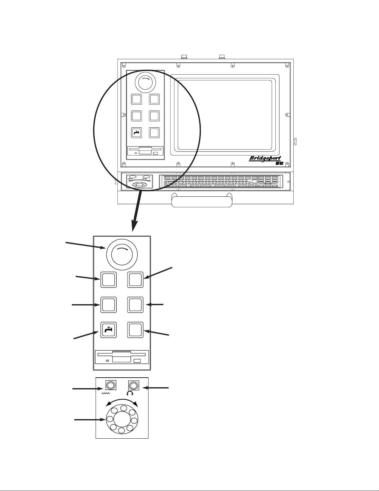
The Operator’s Console (Figure 1-1)
consists of a pendant-mounted VGA Color
monitor, a keyboard, and control buttons.
These controls are used to operate all
functions of the CNC.
The VGA Color monitor displays the
screen menus from which the operator can
select control functions.
The keyboard provides the basic means
for communicating with the DX32 control.
The keys are organized into five groups,
they are:
1. Main Keyboard This includes all
the keys normally found on a
typewriter.
2. Numeric Keypad This includes
numbers 0-9, decimal point and
mathematical function keys. It is
used with pop-up menus on the
screen to select various control
functions.
1-3
S%
F%
E
T
EE
NN
C
Y
-
S
G
R
P
-
S
T
O
E
M
Y
E
M
E
R
O
P
G
E
N
C
START
STOP
+
_
SPINDLE
STOP
E
T
EE
NN
C
Y
-
S
G
R
P
-
S
T
O
E
M
Y
E
M
E
R
O
P
G
E
N
C
START
STOP
+
_
SPINDLE
STOP
F%
S%
STOP
SWITCH
START
SWITCH
JOG +
JOG –
COOLANT
ON/OFF
SPEED %
POT
EMERGENCY
STOP
FEED %
POT
AXIS
MOTION
ENCODER
SPINDLE
STOP
Figure 1-1
OPERATOR'S CONSOLE

3. Function Keys These enable the operator to select special functions that are
assigned to each key.
4. Screen Control Keys These enable the operator to select data from different
locations on the screen display, particularly in Edit mode.
5. Special Keys These keys communicate directly to the operating system.
The control buttons each have a specific function. These functions are used in setting up a
part and running a part program.
START Pressing the START button begins operation of the part program at the
current line of the part program text. START also resumes execution
after an interruption such as PROGRAM STOP or system HOLD.
STOP This button stops part program execution and interrupts axis motion
without loss of the program position. All axes decelerate to a smooth
stop unless a tapping (G84) cycle is in progress. During a tapping or
tool change cycle, the machine motion continues until the end of the
cycle. The perimeter door guards can be opened at this time, which
causes the spindle and coolant to shut off. When the doors are closed,
the spindle and coolant will return to their previous conditions.
NOTE: In RAPID TRAVERSE (G0) motion may continue up to 0.2
inches after STOP is pressed. The active registers are not lost. To
continue, use START.
EMERGENCY
STOP This is a red mushroom button which, when pressed, stops the spindle
motor and axes drives. Program execution is terminated and the system
is set in the System Start Up mode. When EMERGENCY STOP is
pressed, the part program and the tool length offsets (TLOs) are not
destroyed and axis position is not lost. The EMERGENCY STOP button
should only be used when an immediate halt of all motion is absolutely
necessary or when safety is threatened. In normal use the HOLD
button should be used to interrupt axis motion.
To recover from EMERGENCY STOP, first correct the problem which
caused the use of the button. Next, pull out the button and then
execute the AXIS DRIVE ENABLE sequence. Under certain
circumstances the axes drives may need to be re-homed. In this case
the machine will prompt the operator to re-home the machine.
1-4

JOG +/- These are two push-button selector switches. They are used for either
jogging an axis continuously, or in 0.0001 steps.
When 9 JOG is selected from the BASIC menu, pressing the push-
button causes the axis selected from the screen menu to move. There
are two selectable jog motions: FAST and SLOW.
% SPEED This potentiometer is used to change the speed of the spindle. The
requested spindle speed is adjustable from 50 to 200%.
% FEED This potentiometer is used to change the speed of the axis traverse and
programmed feed after the override function has been activated. The
requested feed or traverse rate is adjustable from 0 to 150%.
COOLANT
ON/OFF This switch is a normally-open,momentary push-button which acts like a
toggle switch.If the flood coolant is off,depressing the switch starts the
flow of flood coolant (M8 flood coolant ON).If the flood coolant is on,
depressing the switch stops the flow of flood coolant (M9 flood coolant
OFF).
AXIS MOTION
ENCODER This encoder will generate axis motion on the axis selected by the
operator.The knob,when rotated,causes 0.1 inches of motion for each
revolution when the fast jog is selected,and 0.01 inches of motion when
the slow jog is selected.The speed on the axis motion is controlled by
the speed of the rotation of the knob.
Basic BOSS DX32 Software
PC Software used on the PC consists of System Software, Applications
Software, and User Data.
System
Software System software is the essential collection of programs the DX32 needs
before you can use it. The operating system used on the PC is MSDOS. MS-DOS (DOS) is a collection of routines that perform basic
tasks such as starting (or booting up) the computer, moving data to and
from disks and peripheral devices, and managing and allocating
memory space in RAM. The most frequently used DOS System
commands are described in this manual. For more information on
DOS, refer to the MS-DOS User’s Reference Manual.
1-5

DOS is the bottom layer of software used on the PC. In normal
operation, it is not necessary to access the DOS level. Upon start-up, a
routine called AUTOEXEC.BAT automatically loads the DX32 specific
applications software. For advanced users DOS can be accessed via the
START-UP menu.
Applications
Software The routines that call the front panel screens and perform the
commands selected from the screen menus are contained in a program
named BXX.EXE. The software driver which controls axis drive
functions, and executes machine instructions is called BMDC.BIN. For
information on updating the applications software, see Chapter 7.
NOTE: The programs BXX.EXE (which runs on the PC) and BMDC.BIN
(which runs on the BMDC) are essentially independent of each other.
Status and text data are passed between the two programs as required.
This enables concurrent use of the systems. For example, the PC can
be used to edit a program while the BMDC is machining a part, or the
PC can be in the Diagnostic Mode monitoring the servo performance
while the BMDC is running diagnostic moves.
There are DOS level errors that can stop execution of BXX.EXE. The
most frequent error occurs when no disk or an improper disk is
mounted in the disk drive. DOS flags the error and breaks to the DOS
system level. To resume operation, type RUN when the DOS prompt
(C>) appears.
User Data User Data consists of part programs and tool data. The file extension
.TXT is appended to part program text. The file extension .DAT is
appended to tool data.
BMDC BOSS DX32 is the Operating System used on the BMDC. Previous
Bridgeport CNC systems had BOSS imbedded in ROM. On the DX32,
BOSS is loaded into RAM located on the BMDC board.
DX32 SYSTEM DISK
The software described above is stored on the hard disk, as well as a
3.5 inch floppy backup disk. System software and user data may reside
on the same disk, however, this does limit the amount of available
space for storing user data. It is strongly suggested that backup copies
of the system software be kept in a safe place (away from extreme heat,
cold, or humidity, magnets, oil and dust).
1-6

CHAPTER 2
STARTING UP THE DX32
Introduction
The procedure detailed in this chapter is necessary to properly start the DX32 System. Make
certain that all set up and pre-start maintenance has been completed before attempting to
start the machine.
Before Starting the DX32
Make a careful check of the following conditions before applying power.
1) Check level of lubricating oil, refill if low.
2) Check position of all axes with respect to fixtures or other parts left on the
table.
3) Check air pressure level, adjust to nominal psi.
CAUTION!!
If there are ANY problems with any of the prestart checks, DO NOT start the
machine. Check the Maintenance Manual for proper start up maintenance
procedures. Failure to do so may result in machine damage.
Turning on the DX32
The DX32-controlled machines boot automatically from the standard hard disk contained
within the control cabinet. Before turning on the MAIN DISCONNECT, make sure that the
floppy disk drive is empty. To power up the system, move the MAIN DISCONNECT switch,
located toward the rear of the machine, to the ON position.
The system will then run through its STARTUP diagnostics and loads the BMDC.BIN software
to the BMDC. The system also verifies the integrity of the driver code stored in the BMDC
RAM. If the driver code has been corrupted, the system prompts the operator to load a new
version of the driver code. This would require inserting the backup software disk and
following the update or install instruction found in Chapter 7. If the driver code is okay, the
STARTUP routine then automatically loads and executes the DOS-based DX32 System
Software. The START-UP SYSTEM Menu then appears on the screen. See Figure 2-1 below.
2-1
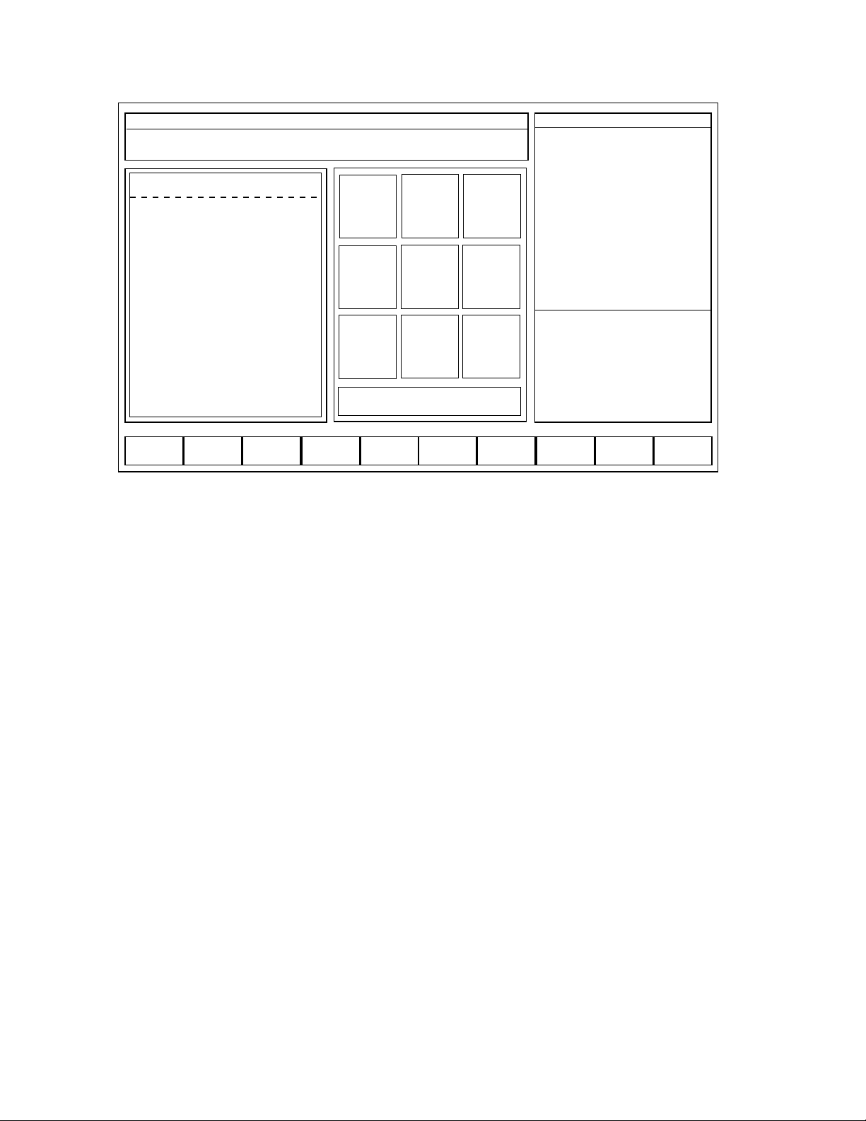
Figure 2-1
To start the system from a floppy disk, (System Disk only), put the disk into the disk drive
BEFORE turning the MAIN DISCONNECT on.
NOTE: The SYSTEM MODE status window (top line in the screen) displays the
current version number of the DX-32 software. Always reference this
number when calling Bridgeport for technical support.
Modes of Operation
The DX32 uses any one of four basic modes during machine operation. They are:
STARTUP BASIC OPERATION SETUP RUN
The default mode after system initialization is STARTUP. The BASIC OPERATION menu is
automatically displayed after the axis drives are enabled and the axes are homed. The
SETUP mode is made active by selecting F3 SETUP from the BASIC menu. The RUN mode
is made active by selecting F4 RUN from the BASIC menu.
STARTUP
This mode is the first active mode after the system is booted up.
The system commands available from the STARTUP screen are:
2-2
BOSS DX/32 V4.08/6.41
MON JAN 14 03:15:04 PM
Copyright (c) 1988-1995 BRIDGEPORT MACHINES, INC.
[C;\ bytes free = 259596288]
BRIDGEPORT DX/32 CNC
This software is subject to revision
and enhancement. To receive
software updates register your
system by calling BRIDGEPORT
CONTROLS at 215-788-8484.
Please give us your NAME/ TITLE/
COMPANY/ ADDRESS/ CITY/
STATE/ ZIP/ PHONE/ FAX/
DEALER/ and CNC SERIAL NO.
[FAX 215-788-0734]
1
SET
PARAMs
23
JOGoff
LIMITS
4
LOAD
Remote
5
FILES
6
Tool
Change
7
AXSDRV
ENABLE
8
HOME
AXES
9
DOS
0 SELECT BASIC MENUS
F1
F2
N-SEE
F3
WINDOWS
F4
EZ-SPS
F5 F6
dataNET
F7
DIGITIZF8SUProbe
F9
LDmdcSW
F10
Params
CNC MAN ABS B8&
MODE:
SEQ NO:
TOOL NO:
TLO:
DIA:
TIME:
S, ACT
F, IPM
F, OVR (OFF)
X ABS
Y ABS
Z ABS
SPINDLE:
COOLANT:
BAPID, IPM:
OPSELSW:
OPROTSW:
DRYRUN:
/ DELETE:
OPSTOP:
SETUP
0
9
7.0000
0.5000
000:00:00
0 75%
000.0
80%
12.4214
8.9717
7.1614
OFF
OFF
OFF
OFF
OFF
OFF
OFF

1 SET PARAMs
Refer to Maintenance Manual.
3 JOGoff LIMITS
This provides the ability to jog-off the axis limit switches. This may be necessary
prior to homing if the axis position is such that a limit switch is actuated.
4 LOAD Remote
This provides a communications link to remote devices.
5 FILES
This provides the ability to DELETE, RENAME, COPY and APPEND DATA and
TEXT files.
6 TOOL CHANGER
This command accesses Tool Changer settings. This command gives the user the
ability to load the tool magazine with tools and home the magazine when done.
This command is also where the tool change setup is done (refer to the
maintenance manual on tool change setup).
7 AXSDRV ENABLE
This command turns on power to all the axis drives.
8 HOME AXES
This command initiates the machine homing sequence.
9 DOS
This command exits to the MS-DOS operating system.
0 SELECT BASIC MENUS
This command selects the BASIC OPERATIONS screen display.
The displayed STARTUP commands which can be executed using the Function keys are:
F2 N-SEE
[Enhanced Performance Option] This command executes the N-SEE software.
F3 WINDOWS
[Enhanced Performance Option] This command exits to the Microsoft Windows
environment.
F4 EZ-SPS
[Option] This command exits to the Bridgeport Simplified Programming System.
2-3

F6 dataNET
This command links with a high-speed data network for client-server based
communications. This network option is not offered by Bridgeport, it must be
installed by the user.
F7 DIGITIZ
[Digitizing Software Option] This command exits to the Bridgeport Digitizing
software.
F8 SUProbe
This command enables or disables the Probe.
F9 LDmdcSW
This command enables reloading the machine software (BMDC.BIN) into the
BMDC.
F10 Params
This command enables the operator to configure certain system parameters.
(i.e. backlash, rapid and jog rates)
The [ESC] key is used to clear the EVENT STATUS messages.
NOTE: Pressing [ESC] does not correct the cause of the ERROR message. The error
condition must be corrected before the machine can continue to operate.
During an alarm condition, the blinking “ALARM” message needs to be cleared
with the “ESC” key BEFORE any other command will be executed, such as
spindle off, quill up, etc.
BASIC OPERATION
For simplified operation, the BASIC OPERATION menu contains the most frequently
used operator commands. In normal operation, all the commands necessary to set up
and run the DX32 can be selected from this screen.
Less frequently used DX32 commands can be accessed from the BASIC OPERATION
menu by accessing the STARTUP, SETUP, and RUN menus.
This mode is discussed in greater detail in Chapter 3 in this manual.
SETUP
The SETUP screens prepare the machine for part making. This includes establishing
machine reference points, tool characteristics, initial axis positions, and loading part
programs.
The EDIT function can be accessed through the SETUP mode. This mode is discussed
in greater detail in Chapter 4 in this manual.
2-4
RUN
This mode runs a part program that has been previously loaded into BMDC RAM either
in Automatic or Block mode. RUN mode also works with DNC LINK (Direct Numerical
Control).
The MDI function can be accessed in the RUN mode. This mode is discussed in
greater detail in Chapter 6 in this manual.
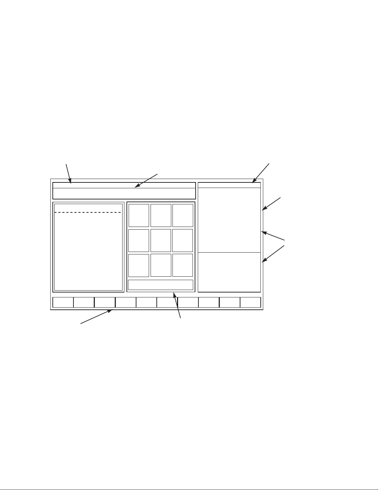
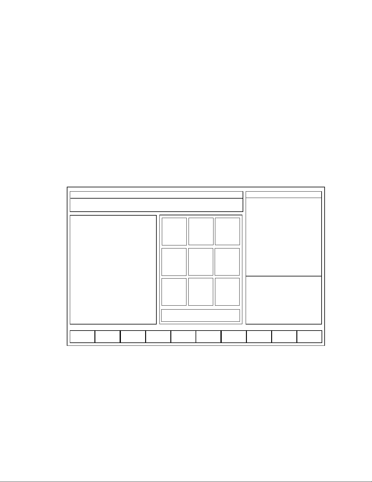
Reading the CRT
The DX32 screen contains the fields shown in Figure 2-2, below.
Although the initial reaction to the DX display may be that the screen looks cluttered with
data, the screens are actually set up in a consistent, informative manner. The object is to
present as much information as possible without requiring the operator to access additional
layers of data.
The screen display consists of the following windows:
2-5
BOSS DX/32 V4.08/6.41
MON JAN 14 03:15:04 PM
Copyright (c) 1988-1995 BRIDGEPORT MACHINES, INC.
[C;\ bytes free = 259596288]
BRIDGEPORT DX/32 CNC
This software is subject to revision
and enhancement. To receive
software updates register your
system by calling BRIDGEPORT
CONTROLS at 215-788-8484.
Please give us your NAME/ TITLE/
COMPANY/ ADDRESS/ CITY/
STATE/ ZIP/ PHONE/ FAX/
DEALER/ and CNC SERIAL NO.
[FAX 215-788-0734]
1
SET
PARAMs
23
JOGoff
LIMITS
4
LOAD
Remote
5
FILES6Tool
Change
7
AXSDRV
ENABLE
8
HOME
AXES
9
DOS
0 SELECT BASIC MENUS
F1
F2
N-SEE
F3
WINDOWS
F4
EZ-SPS
F5 F6
dataNET
F7
DIGITIZF8SUProbe
F9
LDmdcSW
F10
Params
CNC MAN ABS B8&
MODE:
SEQ NO:
TOOL NO:
TLO:
DIA:
TIME:
S, ACT
F, IPM
F, OVR (OFF)
X ABS
Y ABS
Z ABS
SPINDLE:
COOLANT:
BAPID, IPM:
OPSELSW:
OPROTSW:
DRYRUN:
/ DELETE:
OPSTOP:
SETUP
0
9
7.0000
0.5000
000:00:00
0 75%
000.0
80%
12.4214
8.9717
7.1614
OFF
OFF
OFF
OFF
OFF
OFF
OFF
System Mode
Operator Instructions
Data Display Areas
Numeric Keypad Commands
Special Function Commands
System Run and Aux Status
MDC Event Message
Figure 2-2.

System Mode
This is a one line status message which displays the System MODE. A real time clock
is also displayed on this line.
Operator Instructions
This is a two line message containing information for the operator. A blinking arrow
at the top right hand side of the window indicates when operator input is required.
NOTE: There are two kinds of input required from the operator:
1) A <NUMERIC KEY> or <FUNCTION KEY> selection may be required to
perform the desired command.
2) A DATA field entry may be required. The only way to complete a DATA field is
to press the <ENTER> key once the data has been satisfactorily entered, or the
<ESC> key to CANCEL the command.
Data Display Areas
The data display areas are used to show important system information, such as AXIS
POSITION, PART PROGRAM TEXT, TOOL TABLES, etc.
Numeric Keypad Commands
These show the available commands which can be selected with individual keys on
the keypad.
Special Function Commands
These show the available commands which can be selected with individual function
keys on the keyboard.
System Run and Aux Status
These show the state of the MDC controller. All key data registers and mode bit flags
are displayed. The TOP line of the RUN STATUS display is particularly important, it
shows whether the system is OFF, in MANual mode, in RUN mode, or in HOLD. It
also indicates whether input is ABS or INC and whether the system is in B4-7 or B8&
mode.
MDC Event Message
This is a one line event status message that displays run time dependent messages.
For example, it will show fault or error messages.
2-6

Homing the Axes
From the STARTUP screen, press 7 AXSDRV ENABLE to power up the drives. Next, press 8
HOME AXES twice to initiate the machine homing sequence. This causes the Z axis to
move up to the “Home” position and the X and Y axes, and C if installed, to move to their
“Home” positions in sequence. The tool changer will also position itself to the current tool
position.
NOTE: Perimeter guard doors need to be closed to initiate the homing process.
Once the tool carousel is finished homing the doors can then be opened.
The SYSTEM STATUS window shows the X ABS, Y ABS, and Z ABS position,
and C ABS if installed. Prior to homing, Not Homed is displayed. If an Axis
LIMIT has been exceeded, the OPERATOR’S INSTRUCTION window reads:
Following the directions, use the JOG knob to move the axis off the Limit.
CAUTION!! Be sure to select the correct jog direction.
Additionally, the EVENT STATUS window may display an ERROR message describing a
System Fault.
Normal Shutdown Procedures
Use the following procedure to shutdown the machine for either overnight or extended
periods of time.
1) Select BLOCK mode or wait for a tool change block if a program is
running.
2) Turn spindle OFF.
3) Depress EMERGENCY STOP.
4) Switch machine Main Disconnect to OFF.
Power Failure
Loss of power to the machine for more than 1/60 of a second (1 cycle) causes a system
shutdown. Use the initial system start up procedure to restart the machine after power
failure.
2-7
—>X AXIS LIMIT —— Use JOG KNOB to MOVE OFF LIMIT

NOTE: System RESET may be required if power was off for less than
one half second.
System Reset
Pressing the RESET push-button switch sets the DX32 in an initial start up condition. Follow
the start up procedure.
System Configuration
Pressing the F10 XT Params key allows the operator to set various system parameters. The
UP and DOWN arrow keys are used to select the parameter to be changed. The system
parameters that can be set via the Params screen are:
MAX RATE
Entering a value here sets the rapid traverse rate (G0).
JOG RATE
Entering a value here sets the jogging traverse rate.
BACKLASH COMPENSATION
Entering a two (2) digit number from 2 – 25 sets the designated backlash
value into the system.
The system configuration values are saved in a file named BMDCPRMS.SYS.
It is VERY important that the DX32 BACKUP DISK is matched with the
machine that it is to be used with, otherwise, configuration values may
not be set properly.
2-8
Chapter 3
BASIC OPERATIONS
The BASIC OPERATION mode contains the commands most frequently used by the
operator. The following operations are available from the BASIC OPERATIONS menu.
1) Axis jog, axis motion and establishment of machine/part program coordinate
system.
2) Entering, storing, and loading Tool Data.
3) Setting of RUN mode – RESET program, AUTO, BLOCK.
4) Operation of machine functions – COOLANT, FEEDRATE OVERRIDE.
5) Loading part programs.
6) Editing part programs.
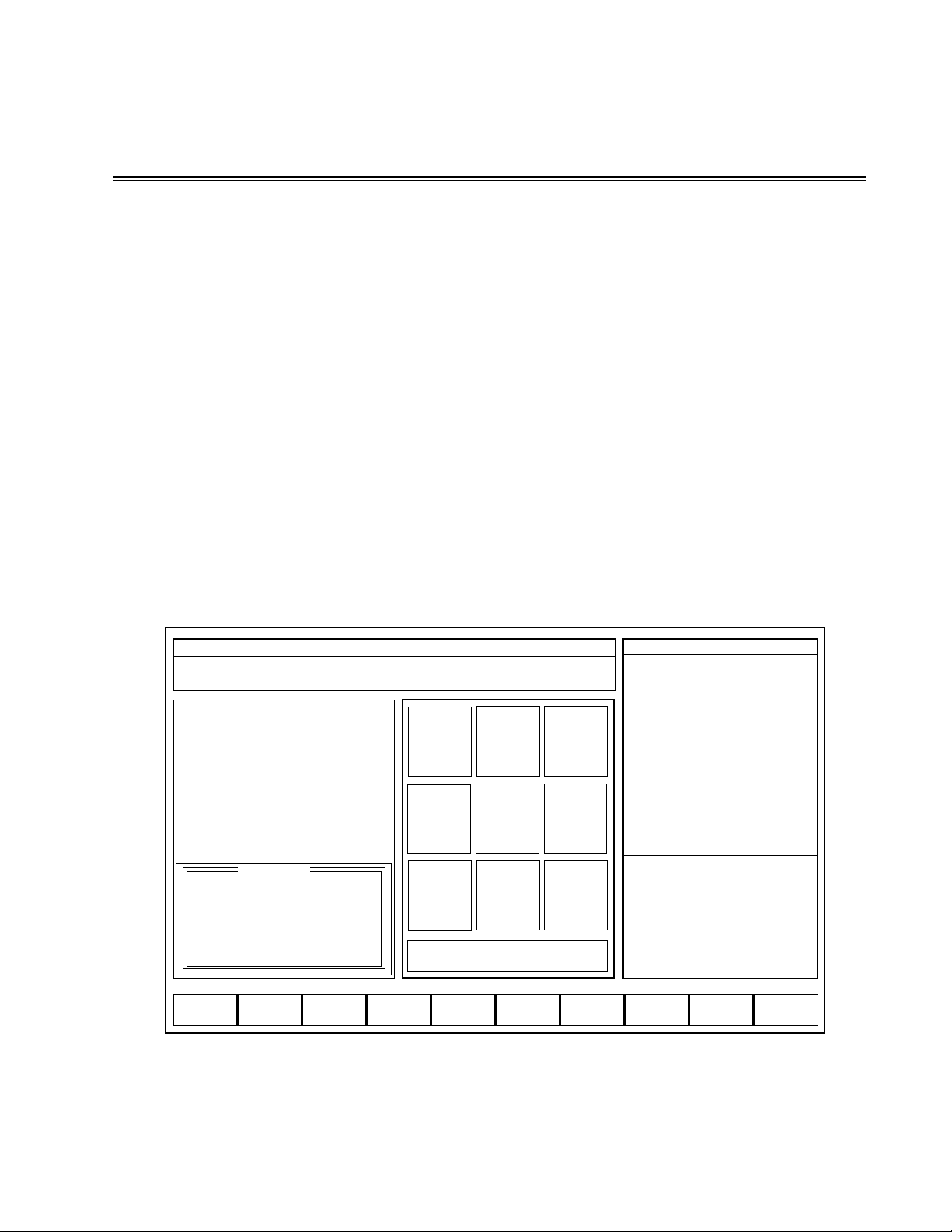
Basic Operation Screen
The BASIC OPERATION screen appears as shown in Figure 3-1.
Figure 3-1
3-1
BASIC | |
MON JAN 14 03:15:04 PM
Use <f KEY> or <NUM KEY> to select FUNCTION
Cursor Up/Dn for Feed Override (5% increments)
1
AUTO
2
BLOCK3FEED
OVR
4
FND
:_ N_ T_
5
RESET
PGM
6
S_ T_ M_
7
SET
T//
8
SET
TNO
9
JOG
0 EXIT BASIC MENUS
F1
F2
S_/OFFF3SETUPF4RUN
F5
PREVIEW
F6
EDIT
F7
LOAD
F8
COOLANT
F9
QU UP
F10
CNC MAN ABS B8&
MODE:
SEQ NO:
TOOL NO:
TLO:
DIA:
TIME:
S, ACT
F, IPM
F, OVR (OFF)
X ABS
Y ABS
Z ABS
SPINDLE:
COOLANT:
BAPID, IPM:
OPSELSW:
OPROTSW:
DRYRUN:
/ DELETE:
OPSTOP:
SETUP
0
9
7.0000
0.5000
000:00:00
0 75%
000.0
80%
12.4214
8.9717
7.1614
OFF
OFF
OFF
OFF
OFF
OFF
OFF
C:
PRV:
CUR:
NXT:
X
Y
Z
12.4214
8.9717
7.1614

The key commands available from the BASIC OPERATIONS screen are as follows:
0 EXIT BASIC MENUS This command will exit the BASIC OPERATIONS mode and
return the operator to the STARTUP screen.
1 AUTO This command sets the system in RUN/AUTO mode. Hitting the START button
begins automatic execution of the part program.
2 BLOCK This command sets the system in RUN/BLOCK mode. Hitting the START
button begins block by block execution of the part program.
3 FEED OVR In RUN mode, this enables the use of the feed override potentiometer to
override programmed feedrates. When feed override is set to ON, the feed override
knob enables the overriding of rapid traverse and feed motion commands from 0% to
150%. When the feed override function is set to OFF, all motion commands return
back to executing at 100%, regardless of the feed override knob position.
NOTE: Spindle override – Whenever the spindle is rotating, the spindle override
knob is active, which enables the override of the programmed RPM from
50% to 200%.
4 FIND :_N_T_ This command searches the part program for a particular :,
N (Sequence Number), or T (Tool Number) value.
5 RESET PGM This command will reset the part program text pointer back to the top of
the program. It also initializes the system RUN registers.
6 S_T_M_ This command allows the input of S, T, and M values. (Spindle Speed,
Tool #, or Miscellaneous function)
7 SET T// This command allows the direct input of TLO and DIA values.
9 JOG This command calls the JOG screen. In addition to Axis JOG and MOTION
commands, the JOG screen contains a convenient set of commands for setting the
machine up. It will be discussed further in this chapter.
F2 S_/OFF This command shuts off the spindle.
F3 SETUP This command will bring up the SETUP screen. It will be discussed further in
Chapter 4 of this manual.
F4 RUN This command will bring up the RUN screen. It will be discussed further in
Chapter 5 of this manual.
F5 PREVIEW This command will provide a graphical display of the tool path. It will be
discussed further in this chapter.
3-2
F6 EDIT This command brings up the editor to allow the operator to make changes to
the part program. See Chapter 6 in this manual.
F7 LOAD This command loads a part program that is stored on disk to the CNC. It also
executes a RESET PGM command. It will be discussed further in this chapter.
F8 COOLNT This command selects FLOOD or MIST coolant, and turns the coolant
either ON or OFF.
F9 QUILL UP This command moves the Z axis to the UP (HOME) position.
Jogging the Axes
After the axes drives have been enabled and the axes have been homed, the BASIC
OPERATION mode can be used to set up and run the DX32. Pressing the 9 JOG key from
the BASIC OPERATION menu will bring up the screen shown in figure 3-2.
Figure 3-2
The commands available from the JOG screen are:
1 JOG X
4 JOG Y
7 JOG Z
5 JOG C (if installed)
These commands are used to select the axis that is to be jogged. A blinking number
indicates which axis has been selected.
3-3
SETUP || JOG |
MON JAN 14 03:15:04 PM
Select AXIS/MODE: <+> = MOVE X_Y_Z_ <-> = MOVETO PT [ ]
<.> = PROBEPT </> = SAVEPTS
1
JOG
X
2
JOG
SLOW
3
JOG
FAST
4
JOG
Y
56
7
JOG
Z
89
0 EXIT JOG MENU
F1
F2
TEACHF3Z PTS
F4
GEOM
F5
GoCLRPT
F6
SET X
F7
SET YF8TLO = Z
F9
QU UP
F10
ABS/INC
CNC MAN ABS B8&
MODE:
SEQ NO:
TOOL NO:
TLO:
DIA:
TIME:
S, ACT
F, IPM
F, OVR (OFF)
X ABS
Y ABS
Z ABS
SPINDLE:
COOLANT:
BAPID, IPM:
OPSELSW:
OPROTSW:
DRYRUN:
/ DELETE:
OPSTOP:
SETUP
0
9
7.0000
0.5000
000:00:00
0 75%
000.0
80%
12.4214
8.9717
7.1614
OFF
OFF
FXAXS
FXAXS
OFF
OFF
OFF
X
Y
Z
12.4214
8.9717
7.1614
1
2
3
4
5
6
7
8
-4.2150
6.0698
6.0698
-1.5723
1.8024
2.1276
1.9650
0.0000
9.0225
-0.5076
5.3724
1.5063
3.3186
3.2730
3.2958
0.0000
-4.3115
-4.3115
-4.3115
-4.3115
-4.3115
-4.3115
-4.3115
0.0000

2 JOG SLOW
3 JOG FAST
These commands select the resolution for jog motion. Jog is executed by rotating the
incremental jog knob or by pressing one of the two jog switches (+,-). In JOG SLOW
the resolution of the incremental jog knob is 0.01/rev and the selected jog axis is
moved 0.0001” each time the jog switch is pressed. In JOG FAST the resolution of
the incremental job knob is 0.1/rev and continuous motion occurs when the jog
switch is pressed.
F2 TEACH
This command enters the TEACH mode. It allows the operator to create a part once,
entering the required points, then having the machine save the moves as a part
program. This will be explained in greater detail further in this chapter.
F3 Z PTS
This command accesses a set of options for positioning the Z-Axis.
3-4
1
2
JOG
SLOW
3
JOG
FAST
4
JOG
Y
56
7
JOG
Z
89
0 EXIT JOG MENU
SAVE Z
UP PT
GO TO Z
UP PT
SAVE Z
DWN PT
GO TO Z
DWN PT
JOG
X
Z Up Point: This is a Z-axis position usually
some safe distance above the
workpiece which can be saved
for use in the Setup Mode.
Z Down Point: This is a Z-axis position usually
close to or on the workpiece
surface which can be saved for
use in the Setup Mode.
Go to Z Up Pt.
Go to Z Down Pt.:
These commands are used to
position the Z-axis to the Z Up
Point or Z Down Point location
in the Setup Mode.
F4 GEOM
The GEOMETRY mode is used in conjunction with the SAVE POINTS coordinates to
calculate intersections of lines, centers of rectangles or radii.
While in the JOG mode, the OPERATOR INSTRUCTION window displays the following
message:
Select AXIS/MODE: <+>=MOVE X_Y_Z_ <->=MOVETO PT
<.>=PROBEPT </>=SAVEPTS

If <+> MOVE XYZ is pressed, the OPERATOR INSTRUCTION window will display:
ABS indicates the input mode. Press <ENTER> without a value to advance the input pointer
past a field. After the X,Y, and Z move values are entered, the OPERATORS INSTRUCTION
window displays:
Pressing the <+> key moves the axes to the desired position.
If </> SAVE PTS is pressed, the OPERATOR INSTRUCTION window will display:
Entering a value from 1 through 8 stores the coordinates of the point in the saved
POINT table.
If <-> MOVE TO PT is pressed, the axes can be moved to a previously saved point in the
POINT table. The OPERATOR INSTRUCTION window displays:
After the desired saved point has been entered the OPERATOR INSTRUCTION window
displays:
Hitting the <+> key moves the table to the previously save position.
The <.> key selects the PROBEPT mode. This mode is used with a touch probe to touch off
points on the part surface. When the <.> key is pressed, the keypad display reads:
3-5
—>MOV X__________<ENTER> Y_________<ENTER> Z_________<ENTER>
ABS Hit <ESC> to CANCEL
—>MOVE X 1.0000 <ENTER> Y 2.0000 <ENTER> Z 0.0000 <ENTER>
<+> to MOVE XYZ or <ESC> to CANCEL
—>SAVE XY PT [1 thru 8] [ ] <ENTER> <ESC>=CANCEL
@ X1.0000 Y2.0000 Z0.0000
—>GOTO XY PT [1 thru 8] <HIT 1–8> or <ESC> to CANCEL
<+>=GOTO XYZ PT.
—>MOVETO PT [ 1 ] X1.0000 Y2.0000
<+> to MOVE XY or <ESC> to CANCEL
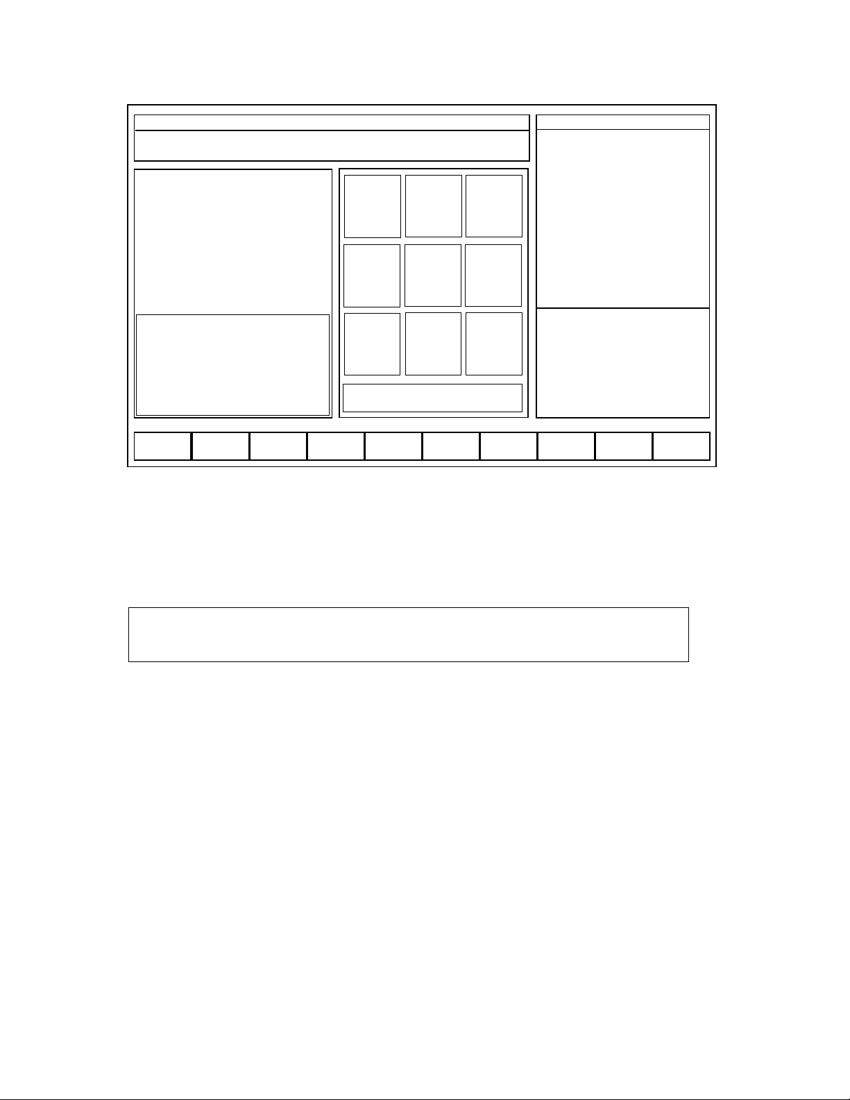
Figure 3-3
Use 2 PROBE -X, 3 PROBE +X, 5 PROBE -Z, 6 PROBE -Y, or 9 PROBE +Y to move the
probe into the part. After the probe hits the part, it automatically prompts the operator to
save the touch point and backs off from the part. The OPERATOR INSTRUCTION window
displays:
Entering a value from 1 through 8 stores the saved probe touch point in the stored POINT
table.
NOTE: The probe keys are situated so as to help the operator determine the
direction of the probe motion. If the probe does not come in contact
with the part before traveling 1.5”, it will return to its start point.
The F2 TEACH key selects the TEACH mode. In this mode, after the axes have been moved
using the JOG commands, TEACH commands are available to write the current coordinate
values into a file called TEACH.TXT.
WARNING!! Entering the TEACH mode will overwrite the contents of the previous TEACH
file. If another TEACH.TXT file exists, use the 5 FILES selection in the STARTUP menu
(Chapter 2) to rename the existing TEACH file.
3-6
—> SAVE XY PT [1 THRU 8]: <ENTER> <ESC>=CANCEL
@X1.0000 Y2.0000
SETUP | | JOG |
MON JAN 14 03:15:04 PM
PROBE XYZ | | Select PROBE AXIS:
or <ESC> = CANCEL
1
JOG
Z
2
PROBE
-X
3
PROBE
+X
4
JOG
Y
5
PROBE
-Z
6
PROBE
-Y
7
JOG
Z
89
PROBE
+Y
0 EXIT JOG MENU
F1
F2
TEACHF3Z PTS
F4
GEOM
F5
GoCLRPT
F6
SET X
F7
SET YF8TLO = Z
F9
QU UP
F10
ABS/INC
CNC MAN ABS B8&
MODE:
SEQ NO:
TOOL NO:
TLO:
PROBE
TIME:
S, ACT
F, IPM
F, OVR (OFF)
X ABS
Y ABS
Z ABS
SPINDLE:
COOLANT:
BAPID, IPM:
OPSELSW:
OPROTSW:
DRYRUN:
/ DELETE:
OPSTOP:
SETUP
0
9
7.0000
ON
000:00:00
0 75%
000.0
80%
12.4214
8.9717
7.1614
OFF
OFF
FXAXS
FXAXS
OFF
OFF
OFF
1
2
3
4
5
6
7
8
X
Y
Z
12.4214
8.9717
7.1614
2.5338
6.0698
6.0698
-1.5723
1.8024
2.1276
1.9650
0.0000
6.2763
-0.5076
5.3724
1.5063
3.3186
3.2730
3.2958
0.0000
-2.9828
-4.4115
-4.3115
-4.3115
-4.3115
-4.3115
-4.3115
0.0000

When the F2 TEACH key is pressed, the display reads:
Figure 3-4
Upon entering the TEACH mode, N0G0G90 is written as the first block of code in the file
TEACH.TXT.
The key functions for the TEACH mode are:
* This command enters the current coordinate value as a block of text in TEACH.TXT.
If ACK is ON, the <ENTER> key needs to be pressed to enter the data. If ACK is
OFF the data is entered as soon as the * key is pressed.
NOTE: use <ALT I> to toggle ACK OFF/ON. (ACK is the abbreviation for
Acknowledge.)
O This command ends the program. NG0M22 is written and the TEACH mode is
terminated.
T This command enables a T value to be entered. An NG0T1M26 block is written.
S This command enables a PROGRAM STOP. An NG0M20 block is written.
E This command ends the TEACH program.
R This command enables the RAPID mode. The current coordinates are prefixed with
a G0 code. For example, NG0X12.Y7.Z10.
3-7
SETUP || JOG |
MON JAN 14 03:15:04 PM
Select AXIS/MODE: <+> = MOVE X_Y_Z_ <-> = MOVETO PT [ ]
<.> = PROBEPT </> = SAVEPTS <*> = [WR] X_Y_Z_ PT
1
JOG
X
2
JOG
SLOW
3
JOG
FAST
4
JOG
Y
56
7
JOG
Z
89
0 EXIT TEACH MENU
F1
F2
EDI TCHF3Z PTS
F4
GEOM
F5
GoCLRPT
F6
SET X
F7
SET YF8TLO = Z
F9
QU UP
F10
ABS/INC
CNC MAN ABS B8&
MODE:
SEQ NO:
TOOL NO:
TLO:
DIA:
TIME:
S, ACT
F, IPM
F, OVR (OFF)
X ABS
Y ABS
Z ABS
<T>
<S>
<E>
<R>
<M>
<D>
<F>
<ALT_I> ACK OFF
SETUP
0
9
7.0000
0.5000
000:00:00
0 75%
000.0
80%
12.4214
8.9717
7.1614
TEACH.TXT
X
Y
Z
12.4214
8.9717
7.1614
ACK ON RAPID

M This command enables the MILL mode. A prompt requires the feedrate to be
entered. The current coordinates are prefixed with a G1 code. The F code will
appear at the end of the block. For example: NG1X12.Y7.Z10.F10.
F This command enables a quick simplified FACE routine. The axes are assumed to be
at the extreme left and bottom of the surface to be faced, and the current depth is
assumed as the facing depth. A prompt asks for X, total X distance; Y, total Y
distance; Y, step Y distance; and F, feedrate. A routine to face the surface is
automatically generated.
F2 EDI TCH
This command sets the system in the EDIT mode for modifying the TEACH.TXT file.
On exiting from the editor, the system returns to the TEACH mode.
F3 Z PTS
This command accesses a set of screen commands for positioning the Z-Axis.
(See Page 3-4.)
The F4 GEOM key selects the GEOMETRY mode. This mode is used together with the
stored POINT table to construct the Midpoint of a Line, Midpoint of a Parallelogram,
Intersection of Two Lines, or the Center of a Circle. When the F4 GEOM key is pressed, the
keypad display reads:
Figure 3-5
3-8
SETUP || JOG |
MON JAN 14 03:15:04 PM
CALCULATE Geometry | | Select FUNCTION
or <ESC> = CANCEL
1
JOG
X
2
JOG
SLOW
3
JOG
FAST
4
JOG
Y
5
MID PT
RECT
6
CENTER
3 PTS
7
JOG
Z
8
MID PT
2 PTS
9
INT OF
2 LNS
0 EXIT JOG MENU
F1
F2
TEACHF3Z PTS
F4
GEOM
F5
GoCLRPT
F6
SET X
F7
SET YF8TLO = Z
F9
QU UP
F10
ABS/INC
CNC MAN ABS B8&
MODE:
SEQ NO:
TOOL NO:
TLO:
DIA:
TIME:
S, ACT
F, IPM
F, OVR (OFF)
X ABS
Y ABS
Z ABS
SPINDLE:
COOLANT:
BAPID, IPM:
OPSELSW:
OPROTSW:
DRYRUN:
/ DELETE:
OPSTOP:
SETUP
0
9
7.0000
0.5000
000:00:00
0 75%
000.0
80%
12.4214
8.9717
7.1614
OFF
OFF
FXAXS
FXAXS
OFF
OFF
OFF
X
Y
Z
12.4214
8.9717
7.1614
1
2
3
4
5
6
7
8
-4.2150
6.0698
6.0698
-1.5723
1.8024
2.1276
1.9650
0.0000
9.0225
-0.5076
5.3724
1.5063
3.3186
3.2730
3.2958
0.0000
-4.3115
-4.3115
-4.3115
-4.3115
-4.3115
-4.3115
-4.3115
0.0000

The key functions for the GEOMETRY mode are:
5 MID PT RECT This command calculates the midpoint of a rectangle by finding the
midpoints of two separate lines of the rectangle. The first two points entered are to
construct the first line, and the second two entered are to construct the second line.
The OPERATOR INSTRUCTION window displays:
For each of the four points, enter the number from 1 through 8 identifying the desired
previously stored point. After four points have been entered, the OPERATOR
INSTRUCTION window displays:
Entering a value from 1 through 8 stores the coordinates of the calculated midpoint in
the saved POINT table.
6 CENTER 3 PTS This command calculates the center point of an arc or circle from
three points lying on the circumference of the circle. The OPERATOR INSTRUCTION
window displays:
For each of the three points enter the number 1 through 8 identifying the desired
previously stored point. Probe diameter is equal to the diameter used when obtaining
the points (probe stylus diameter or edge finder diameter) and In/Out is for whether the
Inside or Outside of the Circumference was touched. After the data is entered the
OPERATOR INSTRUCTION window displays:
Entering a value from 1 through 8 stores the coordinates of the calculated center point in
the saved POINT table.
3-9
—>MIDPT RECT| P [ ] <ENTER> P [ ] <ENTER>
Y = PT: [ ] <ENTER> PT:[ ] <ENTER> <ESC>=CANCEL
—>SAVE XY PT [1 thru 8] ENTER <1–8> <0>=CANCEL
MID PT RECT| X5.0820 Y0.4999
—>CENTER 3 PTS| PT: [ ] <ENTER> PT:[ ] <ENTER> PT: [ ] <ENTER>
Probe Dia: [0.0000] <ENTER> In/Out: [ ] <ENTER> <ESC>=CANCEL
—>SAVE XY PT [1 thru 8] ENTER <1–8> <0>=CANCEL
CENTER 3 PTS. X5.0820 Y0.4999

8 MID PT 2 PTS This command calculates the midpoint between two points, and also
provides information about the two points. The OPERATOR INSTRUCTION window
displays:
For each of the two points, enter the number from 1 through 8, identifying the desired
previously stored point. Probe diameter is equal to the diameter used when obtaining
the points (probe stylus diameter or edge finder diameter) and In/Out is for whether the
Inside or Outside of the Surface was touched. After two points have been entered, the
OPERATOR INSTRUCTION window displays:
D is the distance between the points. A is the angle with respect to the X axis.
Entering a value from 1 through 8 stores the coordinates of the calculated center point in
the saved POINT table.
9 INTOF 2 LNS This command calculates the intersection of two lines. Each line is
determined by two points along the line. Probe diameter is equal to the diameter used
when obtaining the points (probe stylus diameter or edge finder diameter) and LEFT/
RIGHT is for which side of the surface was touched. The OPERATOR INSTRUCTION
window displays:
NOTE: The rules for cutter compensation apply to the left/right selection. The lines
need to be constructed as a typical cutter path would be described (i.e. pt1
pt2 pt3 pt4 not pt1 pt2 pt4 pt3).
For each of the two lines enter the number from 1 through 8, identifying the desired
previously stored points. After four points are entered, the OPERATOR INSTRUCTION
window displays:
3-10
—>INTOF 2 LNS| Probe Dia [0.0000] <ENTER> Left/Right: [ L ] <ENTER>
LN1 PT: [ ] <ENTER> PT:[ ] <ENTER> LN2 PT: [ ] <ENTER> PT: [ ] <ENTER>
—>SAVE XY PT [1 thru 8] ENTER <1–8> <0>=CANCEL
X2LN1 X7.2945 Y-5.3249 Z-0.7087 A89.9301 A-4.6637
—>MIDPT 2 PTS| PT: [ ] <ENTER> PT:[ ] <ENTER>
Probe Dia: [0.0000] <ENTER> In/Out: [ ] <ENTER> <ESC>=CANCEL
—>SAVE XY PT [1 thru 8] ENTER <1–8> <0>=CANCEL
MIDPT X5.0820 Y0.4999 Z-0.7087 D0.8191 A89.9309

Entering a value from 1 through 8 stores the coordinates of the calculated intersection in
the saved POINT table.
Other functions that can be used in JOG mode are:
F5 GOTO CLR PT This command moves the table to the clear point position. The point
from which the move is made is temporarily stored and is automatically entered as
default X and Y values when a MOVETO XYZ PT command is selected. The OPERATOR
INSTRUCTION window displays:
Hitting the <+> key moves the table to the clear point.
F6 SET X
F7 SET Y These commands enable the operator to set a part program coordinate value
to the current position. The OPERATOR INSTRUCTION window displays:
F8 TLO = Z This command sets the TLO (Tool Length Offset) for the designated tool
equal to the current Z coordinate value and provides the ability to enter a cutter
diameter. The OPERATOR INSTRUCTION window displays:
After a tool number is entered, the OPERATOR INSTRUCTION window displays:
Entering a value sets the DIAMETER for that tool number in the stored TOOL table.
The TIME represents the total time that the tool has been used.
<*> SET GAGE HEIGHT When the <*> is depressed, the control will prompt for a gage
height distance. If a 1” gage block is being used to set TLO’s, by entering 1.0 the control
will automatically add 1” to the current Z axis location for establishing the correct Z
datum for that particular tool.
3-11
—>Use <+> = MOVETO CLRPT or <anyKEY> to CANCEL
—>SET X [ ] <ENTER>
Hit <ESC> to CANCEL
—>TLO=Z|| SET TOOLNO: [ ] <ENTER> <*>=SET GAGE HEIGHT
GAGE HEIGHT: [0.0000] <ESC>=CANCEL
TNO: 5 TLO: 0.5000 DIA: [ ] <ENTER> TIME 00:00:00
Hit <ESC> to CANCEL

NOTE: Gage Height will remain active until it is changed.
F9 QUILL UP This command moves the Z axis to the UP (HOME) position.
F10 ABS/INC This command toggles the system between the Absolute and Incremental
input modes.
Using the PREVIEW mode
Pressing the F5 PREVIEW key changes the screen display from BASIC OPERATIONS
SCREEN to the one shown in Figure 3-6.
Figure 3-6
The PREVIEW mode shows a graphical representation of the part program that is loaded into
the CNC. The screen commands available in this mode are:
ESC Exits the PREVIEW mode
F2 Toggle between PAUSE and RUN for pausing or running the file
F3 Toggle between AUTO/BLOCK for continuous execution or block by block
execution of the file
F4 Block between AUTO/BLOCK for continuous execution or block by block
execution of the file
F5 RESPGM resets the part program to the top of the text
3-12
PRGM PREVIEW
ESC EXIT F2 RUN F3 BLOCK F4 F5 RES PGM F6 SKIP F7 CLR SCR F10 ZOOM
F9 VIEW 3D
F9 VIEW 2D
PARTPROGRAM
PAUSE AUTO
N
T
D
X
Y
Z
VIEWSIZE
[MIN, MAX]
X-5.0, 5.0
Y-5.0, 5.0
[2D VIEW]

F6 SKIP allows searching to a (N) sequence or (T) tool number
F7 CLRSCR clears the screen
F8 VIEW 2D selects the 2D view mode
F9 VIEW 3D selects the 3D view mode
F10 ZOOM allows the user to zoom in on a feature in the 2D mode
F7 LOAD from BASIC OPERATIONS SCREEN is used to load a part program from the disk to
the CNC. After a part program is loaded it can be run. Pressing the F7 LOAD key changes
the screen display as shown in Figure 3-7.
Figure 3-7
Depress the ESC key twice to select another directory, i.e., A:\ for selecting the floppy disk.
Use the cursor keys (arrow keys) to select the file to be loaded for execution. Select the
correct path and file name for the part program that is desired. The display will then appear
as shown in Figure 3-8 (next page):
3-13
LOAD [CNC] |||
Use <cursor keys> = OLD FILENAME <ESC> = NEW PATH
F1
F2 F3 F4
F5 F6
F7 F8
F9
F10
PATH 1 C:\ FILE <ENTER>
DEMO.TXT
217.TXT
529.TXT
PART1.TXT
PROJECT.TXT
DIRECTORIES

Figure 3-8
Once the program is selected and the ENTER key is pressed, you will be prompted to load
the program which overwrites the previous program that was running.
NOTE: Overwriting the existing file only applies to the file being deleted from the
part program execution (BMDC) memory and has no effect on the file itself. It
will still reside in its original location, i.e.: C:\.
Pressing <Y> will load the program to the CNC. Press 5 to RESET the program and to set
the system in AUTO mode.
LOAD [CNC] |||
Use <CURSOR KEYS> to move cursor, <ESC> to EXIT
F1
F2 F3 F4
F5 F6
F7 F8
F9
F10
PATH 1 C:\ FILE <ENTER>
DEMO.TXT
217.TXT
529.TXT
PART1.TXT
PROJECT.TXT
DIRECTORIES
WIND
PARTS
TONY
3-14

Chapter 4
SET UP MODE
Introduction
The SET UP mode is used to prepare the machine for part program execution.
The following operations are available:
1) Establishment of machine/part program coordinate system
2) Axis motion to set up positions
3) Axis jog
4) Entering, storing and loading Tool Data
5) Loading part programs
6) Editing part programs
Set Up screen
To enter the SET UP mode, press the F3 SETUP key from the BASIC OPERATIONS screen.
The SET UP screen appears as shown in Figure 4-1.
Figure 4-1
4-1
SETUP | |
MON JAN 14 03:15:04 PM
Use <F KEY or Num KEY> to select FUNCTION
1
WORK
SHIFTS
2
MOVETO
X_Y_Z_
3
JOG
4
SET
TNO
5
SET
CLRPT
6
GO TO
CLRPT
7
SRT
T / /
8
SET
REFPT
9
GO TO
REFPT
0 EXIT SETUP MENU
F1
F2 F3 F4
F5 F6
EDIT
F7
LOAD
F8
F9
QU UP
F10
ABS/INC
CNC MAN ABS B8&
MODE:
SEQ NO:
TOOL NO:
TLO:
DIA:
TIME:
S, ACT
F, IPM
F, OVR (OFF)
X ABS
Y ABS
Z ABS
SPINDLE:
COOLANT:
BAPID, IPM:
OPSELSW:
OPROTSW:
DRYRUN:
/ DELETE:
OPSTOP:
SETUP
0
9
7.0000
0.5000
000:00:00
0 75%
000.0
80%
12.4214
8.9717
7.1614
OFF
OFF
OFF
OFF
OFF
OFF
OFF
CNC T / /
T
01
02
03
04
05
X
Y
Z
12.4214
8.9717
7.1614
TLO
7.0000
7.0000
0.0000
0.0000
0.0000
DIA
0.5000
0.2500
0.0000
0.0000
0.0000
TIME
000:00:00
000:00:00
000:00:00
000:00:00
000:00:00

The key commands available from the SET UP screen are as follows:
0 EXIT SETUP MENU This command returns the screen to the BASIC OPERATIONS
menu.
1 WORKSHIFT (SET X_Y_Z_) This command assigns coordinate values to the current
position of axis motion. It also gives the ability to set G54-G59 workshift
coordinates. Five sets of WORKSHIFT coordinates are available for use in part
program execution. They are set with this function in relationship to the original
part program coordinate system. These workshifts are commanded as G54-G59
within a part program or the MDI mode. This is discussed in more detail further in
this chapter. (See also APPENDIX C: DX32 WORKSHIFT.)
NOTE: G54 is the default workshift coordinate if no other has been commanded.
2 MOVETO X_Y_Z_ This command moves the X, Y, Z axes to the entered position.
3 JOG This command calls up the JOG screen that is described in Chapter 3 of this
manual.
5 SET CLRPT This command allows the operator to set the X, Y position as the
Clearance Point that will be used to facilitate tool changes (M26) or move to XY
Clearance Point and reset Program (M22).
6 GO CLRPT This command moves the axes to the Clearance Point.
note: Clearance Point is a value from machine
home which is not affected by the
resetting of another XY coordinate in the workshift mode.
7 SET T// This command allows the operator to input the values for TLO and DIA.
NOTE: This command does not set the Active Tool Number. It updates the values
stored in the tool table.
8 SET REFPT This command allows the operator to set the X, Y position as a
Reference Point to be used to facilitate subsequent fixture set-ups.
9 GOTO REFPT This command moves the axes to the Reference Point.
The functions keys that are available from the SET UP menu are:
F6 EDIT This command brings up the editor to allow the operator to make changes to
a particular part program.
F7 LOAD This command loads part program data that is stored on disk to the CNC.
4-2

F9 QU UP This command moves the Quill (Z-axis) to the up (HOME) position.
F10 ABS/INC This command sets the system in the Absolute or Incremental position
mode.
DX32 Coordinate Systems
Machine Coordinate System
The Machine Coordinate System is referenced off the mechanical axis limit switches and
the homing marker on the axis motor encoders. When the axes are homed, the X, Y and
Z system registers that track axes motion are set to zero. The Operating System handles
all motion commands in the Machine Coordinate System. This ensures that all moves are
within the axis limits.
Part Program Coordinate System
The operator can set the location of the Part Program Coordinate System with respect to
the Machine Coordinate System. This is done by using the Workshift or SET X, Y
Command in the JOG menu. All user motion commands including MOVE X_Y_Z_
and Part Program Motion Data are entered with respect to the Part Program Coordinate
System. Internally, the Operating System converts the Part Program coordinate values
back to Machine coordinates.
Setting the Part Program Coordinate System
Workshift or SET X, Y Command enables the operator to orient the Part Program
Coordinate System with respect to the Machine Coordinate System. To do this, the
operator enters the values to be set as the Part Program Coordinates for the current
machine position.
Setting Up the Tool Change Clearance Point
The Clearance Point can be used during the tool change operation. This is an arbitrary
point, established by the operator, which allows adequate clearance for the tool change.
Use F9 QUILL UP to move the Z axis to the Home position. JOG the X and Y axes to any
convenient point away from the work piece where operations such as Program Stop or Tool
Change can take place. Then press 5 SET CLR. Use the + key to set the clearance point,
escape to cancel.
4-3

Entering Tool Table Data
Specific tool lengths and diameters can be entered for the tools selected to machine a part.
The following tool data information can be stored.
1) Tool Length Offset (TLO) values
2) Tool Diameter (DIA) values
3) Time tool has been used (Tool Life Management)
The data stored in the DX32 BMDC tool buffers is non-volatile, and is retained in memory
with power off.
Please note the following when working with Tool Table Data.
1) All Tool Data entered into the PC is immediately transferred to the BMDC.
2) Tool Data from the BMDC is automatically entered into the PC on system start
up.
3) Because T values can be imbedded in the part program, the actual T value
used by the BMDC may not be the same as the T value displayed in the Tool
Data window.
Press 7 SET T// to call up the Tool Table screen, which enables entry of TLO and DIA
values. The OPERATOR INSTRUCTION window displays:
Key in the tool number associated with the data to be entered. The following functions can
be accessed with special (non-numeric) characters entered into the TNO field. The
<ENTER> key must be pressed after the desired special character is used.
<-> Clears all the T// values
<R> Reads a previously stored TOOL DATA table from disk.
<W> Saves the current TOOL DATA table by writing them to disk.
<ESC> Exits the SET T// screen.
For both Read and Write T//, the Operator Instruction window prompts for the
name of the File to be read and a window containing the names of all the TOOL
DATA tables previously saved is displayed.
4-4
—>TNO [1 thru 24]: [ ] <ENTER> Hit <ESC> to EXIT
<-> CLR ALL T// <R> Read T// from DISK <W> Write T// to DISK

Tool Length Offsets
Tool Length Offsets can either be entered Manually in the SETUP mode by the following
procedure, or by commands embedded in the part program.
NOTE: The TOOL Tables retain the last value entered Manually, but the part
program can set TLOs only if the previous value of the TLO stored in the
TOOL Table is ZERO (ø).
The TOOL DATA window displays 5 sets of values starting at the current TOOL number. To
display a specific tool number from the 24 stored in the TOOL Table, use the SET T//
command. To scroll the TOOL Table use the UP or DOWN cursor control arrows.
Setting TLOs that have not been pre-measured
When the TLO value for a particular tool has not been pre-measured, it is possible to
use the machine coordinate system to determine the offset. The current Z ABS value
can be entered into the TOOL table by entering a <*> as the TLO value in the SET
T// menu. However, the most convenient method of doing this is by using F8
TLO=Z in the JOG menu.
Press 3 JOG. Insert the desired tool into the machine and clamp the work piece to
the table in the desired location. Using one of the JOG functions, move the Z axis so
that the tip of the tool just touches the “Z” zero position, usually the top of the work
piece. Press F8 TLO=Z. The OPERATOR INSTRUCTION window prompts for the
TOOLNO. Key in the desired Tool number and then hit <ENTER>. The Z ABS value
is entered into the TOOL table.
Use 6 GoCLRPT to move the axes to the clear point and insert the next tool in the
machine. Repeat the process just described. Continue until all TLO values have been
determined for each tool programmed.
Setting TLOs for pre-measured tools
The SET T// command can be used to input TLO data when tool lengths have been
pre-measured. Press 7 SET T//. The OPERATOR INSTRUCTION window displays:
Key in the Tool Number of the TLO to be input and hit ENTER. (Or press <-> to
CLEAR ALL T// values, <R> or <W> to read or write T// data to or from disk, or
<ESC> to exit the SET T// command).
4-5
—>TNO [1 thru 24]: [ ] <ENTER> Hit <ESC> to EXIT
<-> CLR ALL T// <R> Read T// from DISK <W> Write T// to DISK

The SET TLOs message is displayed in the OPERATOR INSTRUCTION window.
The values for the current TLO and DIA are displayed in their respective fields.
To retain the current value press ENTER without keying any data into the field.
The TOOL DATA window displays the 5 successive T// values starting from the Tool
Number that was just entered.
NOTE: Any modification of tool data values made in PC RAM automatically updates
the values stored in BMDC RAM.
Cutter Diameter Compensation
Differences in tool diameter are due to wear during use and to losses during re-grinding.
When a tool diameter is less than the one called for in the part program, the operator must
compensate for that difference. The DX32 Operating System provides the ability to
automatically calculate a new Tool Path based on alterations between the cutter diameter
originally programmed for and the actual tool diameter. This compensation value is entered
into the TOOL Table.
Calculation of compensation value
The compensation value entered is the difference between the programmed diameter
and the actual diameter.
For example: if the programmed cutter is a .500” diameter end mill and the actual
cutter is a .485” diameter end mill, the compensation value entered is -.15”.
If the actual cutter is smaller than the programmed cutter the input value is always
negative. If a larger cutter than the programmed cutter is used, the compensation
value is always positive.
Setting Cutter Diameter Compensation
The SET T// command can be used to input DIA compensation data when the values
are known. Press 7 SET T// and follow the procedure described for entering TLO
data.
4-6
—>TNO:01 TLO: [ ] <ENTER> DIA: [ ] <ENTER>
Enter TLO: <*> to SET TLO=ZABS Hit <ESC> to CANCEL

Moving to Position by Entering X, Y, Z data
Use the 2 MOVETO X_Y_Z_ command when you want to move the axes to a
particular position. The X_Y_Z_ data can either be absolute or incremental. To
switch from the Absolute Mode to the Incremental Mode use the F10 ABS/INC
command.
Moving to Tool Clearance Point
Press 6 GOTO CLRPT. The display reads:
NOTE: When moving to Clearance Point the Z axis moves Home before XY motion
takes place.
Filing and Loading Part Programs
Part programs for the DX32 can be located in three separate locations:
DISK Part programs are stored by name on hard disk. Part program file
names stored on disk have the extension .TXT.
PC RAM When EDIT is used, a part program is read off the disk and loaded into
PC RAM. At the conclusion of the EDIT session, the modified part
program can be filed on disk.
BMDC RAM The part program can be loaded from disk into BMDC RAM. This is the
part program executed by the DX32 in the RUN mode.
NOTE: A part program with the same name may be simultaneously running from
BMDC RAM and edited from PC RAM. The changes made in the EDIT mode
are not used to cut a part until the revised part program is loaded into BMDC
RAM.
4-7
—>Use <+> = MOVETO CLR PT
<ESC> = CANCEL

Loading a part program from a file on DISK to the CNC
Press F7 LOAD to load a part program to the CNC. The display appears as shown in
figure 4-2.
Figure 4-2
Select the PATH and FILENAME to be loaded to the CNC. The display will then
appear as shown in figure 4-3.
F1
F2 F3 F4
F5 F6
F7 F8
F9
F10
LOAD [CNC] |||
Use <CURSOR KEYS> = OLD FILE NAME <ESC> = NEW PATH
DEMO. TXT
217.TXT
529.TXT
P ART1.TXT
PROJECT.TXT
PATH 1 C:\ FILE
<ENTER>
DIRECTORIES
WIND
PARTS
TONY
F1
F2 F3 F4
F5 F6
F7 F8
F9
F10
LOAD [CNC] |||
Enter PATH | | DRIVE:\DIR| <ENTER> <.> = WORKDIR
Use <CURSOR KEYS> to move cursor, <ESC> to EXIT
DEMO. TXT
217.TXT
529.TXT
P ART1.TXT
PROJECT.TXT
PATH 1 C:\ FILE
<ENTER>
DIRECTORIES
WIND
PARTS
TONY
4-8
Figure 4-3

4-9
LOAD PARTPGM to CNC
MON JAN 14 03:15:04 PM
LOAD PARTPGM from FILE: C: \TAP.TXT to CNC
OVERWRITE Existing PARTPGM in CNC?? <Y> or<ESC> = CANCEL
F1
F2 F3 F4
F5 F6
F7 F8
F9
F10
CNC MAN ABS B8&
MODE:
SEQ NO:
TOOL NO:
TLO:
DIA:
TIME:
S, ACT
F, IPM
F, OVR (OFF)
X ABS
Y ABS
Z ABS
SPINDLE:
COOLANT:
BAPID, IPM:
OPSELSW:
OPROTSW:
DRYRUN:
/ DELETE:
OPSTOP:
SETUP
0
9
7.0000
0.5000
000:00:00
0 75%
000.0
80%
12.4214
8.9717
7.1614
OFF
OFF
FXAXS
FXAXS
OFF
OFF
OFF
G0T1M6
S1200M3
M29
G02.1
G84U0.V0.24.F5
M28
M22
Figure 4-4
When the proper file is selected and ENTER is depressed, the display shows the first
16 lines of the file read from the disk (Fig. 4-4). The OPERATOR INSTRUCTION
window displays the message
OVERWRITE Existing PARTPGM in CNC?? This message is
displayed to remind the operator that loading a part program into the CNC overwrites
the part program that was previously run. Press <Y> to continue. A WAIT message is
displayed on the screen indicating the file is being loaded from the disk to the CNC.


Chapter 5
RUN
The RUN mode is used to execute the part program and produce actual parts. The RUN
mode screen display is as shown in figure 5-1.
Figure 5-1
The commands available in the RUN mode are:
1 AUTO This command sets the part program to execute continually.
2 BLOCK This command enables block by block execution of the part program.
3 FEED OVR This command enables using the FEED OVR knob to override feed rates
embedded in the part program. When Feed override is set to ON, the feed override
knob enables the overriding of rapid traverse and feed motion commands from 0% 150%. When the feed override function is set to OFF, all motion commands return back
to executing at 100% regardless of the feed override knob position.
5 RESET PROGRAM This command sets the part program text pointer back to the
beginning of the program. It also initializes system RUN registers.
6 S R/O=PR/ACT This command toggles the S,RPM display between ACTUAL and
PROGRAMMED values.
5-1
RUN | | C:\ DEMO.TXT
MON JAN 14 03:15:04 PM
Use <f KEY> or <Num KEY> to select FUNCTION
Cursor Up/Dn for Feed Override (5% increments)
1
AUTO
2
BLOCK3FEED
OVR
4
SET
TNO
5
RESET
PROGRAM
6
S R/O =
RE / ACT
7
SET
OPTION
89
CLEAR
CNC
0 EXIT RUN MENU
F1
F2
S_/OFF
F3 F4
EDT CNC
F5
MDI
F6
CNC :NT
F7 F8
COOLNT
F9
QU UP
F10
SET DNC
CNC CNC ABS B8&
MODE:
SEQ NO:
TOOL NO:
TLO:
DIA:
TIME:
S, ACT
F, IPM
F, OVR (OFF)
X DLT
Y DLT
Z DLT
SPINDLE:
COOLANT:
BAPID, IPM:
OPSELSW:
OPROTSW:
DRYRUN:
/ DELETE:
OPSTOP:
A-RDY
0
9
7.0000
0.5000
000:00:00
0 75%
000.0
80%
0.0000
0.0000
0.0000
OFF
OFF
OFF
OFF
OFF
OFF
OFF
C:
PRV:
CUR:
NXT:
X
Y
Z
12.4214
8.9717
7.1614

7 SET OPTION This command displays the RUN OPTION screen.
9 CLEAR CNC This command clears out the RUN system registers, part program text or
part program macros, which are described later in this chapter.
0 EXIT RUN MENU This command returns to the BASIC OPERATIONS screen display
and commands.
F2 S/OFF This command turns the spindle off.
F4 EDT CNC This commands displays the last part program loaded on the screen. This
text can be edited and then re-loaded for execution.
F5 MDI This command enables Manual Data Input, block by block execution and
editing of a part program.
F6 FND :NT This command is used to search the part program text for a particular :,
N (Sequence Number), or T (Tool Number) value.
F8 COOLNT This command selects and turns ON and OFF MIST or FLOOD coolant.
F9 QU UP This command moves the Z axis to the HOME or full positive position.
F10 SET DNC This command allows the machine to run part programs that are larger
than 256 thousand characters.
The RUN mode assumes that the part program to be run exists in BMDC RAM or that the
DNC LINK has been established. If the desired program has not been loaded into BMDC
RAM do so by using the commands described in Loading and Filing Part Programs
section.
Before the part program is executed for the first time, or after the system mode has been
changed, the RESET PROGRAM command must be used to initialize the control registers
and set the part program text pointer to the beginning of the text buffer.
NOTE: The file name is automatically inserted as the first line of text. Reading the
file name back from the non-volatile BMDC text buffer when the system is first
started up enables the control to know what the name of the last file loaded
was, even if power has been turned off.
If the operator does not want to run the part program from the top of the text buffer, F6
FND :NT may be used to set the part program text buffer to the beginning of a data block
with a particular Sequence Number, or Tool Number.
5-2

After either RESET PROGRAM or FIND has been used to position the part program text
pointer, the next step is selecting either AUTO or BLOCK program run using either 1 AUTO
(continuous operation of the part program) or 2 BLOCK (block by block) RUN modes.
When using BLOCK mode, the START switch must be pressed to reactivate the program
after each executed block.
If AUTO is in effect and BLOCK is activated, the control finishes the current block and then
stops. Non-motion blocks, such as G91, G90, G71, G4 (dwell), G96, G97, etc., on lines by
themselves change status and update axis registers, but the program does not halt at the end
of non-motion blocks. For example:
In Block Mode
N50 G0X3.Y2. Machine stops execution at the end of the Rapid move
N55 G91 Machine changes mode to incremental and executes the next block
N60 G1X2.Y2.F10 Machine stops execution at the end of the feed move
NOTE: A loop call or a macro call is considered a motion block. A macro
subroutine definition is non-motion. If the operator forgets to turn the spindle
on, only rapid traverse (G0) moves are executed. If a block contains a feed
rate motion command, operation is stopped and the message SPINDLE NOT
ON CANNOT CUT is displayed. The operator must then edit the part program
and insert a spindle ON command (i.e. S1000M3) and restart the program.
At the end of a run, a program M2 command resets the part program text pointer to the first
programmed block. Press START to re-run the program.
NOTE: The program can be interrupted at any time by pressing the HOLD key.
The program can then be resumed without error by pressing START.
Resuming Operation After Power to the Drives has been Disabled
If the EMERGENCY STOP button is pushed, or power fails during part program
execution or if a motion takes place which causes a travel limit switch to be reached,
program execution stops, power to the drives is disabled, and the system is cleared
except for the contents of the XYZ offset registers, tool data and part program text.
To resume operation:
1) Use AXIS DRIVE ENABLE to restore power to the axes drives. Then use the
various JOG options to move off the limit switch, if required.
2) Correct the problem and home the machine if necessary.
3) Using the FIND command, search for a convenient restart point,
preferably a tool change position.
5-3

Modifying Feed Rates
Feed rates may be overridden from 0% to 150% with the FEED OVERRIDE knob. Below 1%
the system goes into a feed HOLD condition.
Press 3 FEED OVR to toggle FEED OVR ON/OFF. The SYSTEM STATUS window indicates
FEED OVR: ON. Rotating the feed override knob changes the programmed feed rate. The
SYSTEM STATUS window indicates F,OVR %: 80 when the knob has been used to turn the
override down to 80% of programmed value. The F: value shown in the display is the
ACTUAL modified value, not the programmed value.
Run Options
Use 7 SET OPTION to view the various RUN options available to be used. The display is as
shown in figure 5-2.
Figure 5-2
DRY RUN Options
The DRY RUN options enable the part program to be tested without fully running the
system.
1 NO Z This command allows the part program to be “proven” with no Z axis
movement.
5-4
RUN | | OPTIONS |
MON JAN 14 03:15:04 PM
Use <NUM KEY> for OPTION
1
NO Z
23
MAX FD
4
OPSTOP
5
/ DEL
6
SET
BRK PT
7
METRIC
8
BOSS
VERS
9
0 EXIT OPTION MENU
F1
F2 F3 F4
F5 F6
F7 F8
F9
F10
CNC CNC ABS B8&
MODE:
SEQ NO:
TOOL NO:
TLO:
DIA:
TIME:
S, ACT
F, IPM
F, OVR (OFF)
X ABS
Y ABS
Z ABS
SPINDLE:
COOLANT:
BAPID, IPM:
OPSELSW:
OPROTSW:
DRYRUN:
/ DELETE:
OPSTOP:
A-RDY
0
9
7.0000
0.5000
000:00:00
0 75%
000.0
80%
12.4214
8.9717
7.1614
OFF
OFF
OFF
OFF
OFF
OFF
OFF
C:
PRV:
CUR:
NXT:
X
Y
Z
12.4214
8.9717
7.1614

NOTE: At an M6 (tool change) command the Z axis moves up to the Tool Change
position and establishes a new NO Z plane of operation.
3 MAX FD This command runs the part program and overrides all programmed feed
rates. Complete operation of the part program can be accomplished with maximum
feed rate to more quickly detect programming errors.
OPERATOR RUN-TIME Options
These options allow the operator to intervene and modify how the part program is run.
4 OPSTOP Enabling this function causes the program to STOP after executing any
data block that contains an MØ1 command.
5 / DEL When / DEL in ON, the system will ignore any part program block that
starts with a slash (/).
6 SET BREAK PT The BRKPT feature is used to allow the operator to stop at a
convenient point in the program. The program stops before the designated sequence
number is executed. When the BREAKPOINT is reached, the system status message
indicates a Program STOP. Press START to resume program execution.
Other RUN Options
7 METRIC This option sets the system to accept all input dimensions as metric
values during the operation of the part program.
NOTE: This does not convert inch programs to metric or metric to inch.
8 BOSS VERS This option provides compatibility with part programs written for
previous Bridgeport CNC machines using BOSS level 4 through 7 software.
5-5


Chapter 6
EDIT/ MDI MODE
The on screen editor provides the ability to enter and edit text. The editor also includes a
G-code help mode that assists the operator in entering part program data.
There are three different methods of accessing the editor. Each of these methods calls up
the same basic functions, the differences are noted below.
EDIT When F6 is selected from the SETUP or BASIC MENU screen, the operator is
prompted for the file to be created or edited. The display shows the directory of all
the previous files created.
EDT CNC When F4 EDT CNC is selected from the RUN screen, the last file loaded
for execution is loaded into the edit buffer.
MDI When F5 MDI is selected from the RUN screen, the file MDI.TXT is
automatically created. As each data block is created, the operator is given the choice
of executing the block. At the end of the MDI session the operator can choose to
store the MDI.TXT file, rename the file, or exit without storing the file.
Commands for Editing Text
After entering the EDIT/MDI mode, the display is as shown in figure 6-1.
Figure 6-1
6-1
EDT CNC | | [bytes free = 2595962887
MON JAN 14 03:15:04 PM
EDIT | |
<+> = G-CODE HELP
F1
F2
EXIT
F3
READ*F4WRITE*
F5
FIND
F6
REPLACE
F7
PRINT
F8
F9
CUT
F10
COPY
CNC CNC ABS B8&
MODE:
SEQ NO:
TOOL NO:
TLO:
DIA:
TIME:
S, ACT
F, IPM
F, OVR (OFF)
X ABS
Y ABS
Z ABS
<ALT_A> MARK
<ALT_D> DEL LN
<ALT_I> INS/OVWR
<INS_KEY> PASTE
<HOME> BEG OF LN,
TOP OF TXT
<END> END OF LN,
BOT OF TXT
<PG UP> <PG DOWN>
A-RDY
0
9
7.0000
0.5000
000:00:00
0 75%
000.0
80%
12.4214
8.9717
7.1614
G0G90
T1M6
S1450M3
M8
N160G173
T15M6
S1750M3
C:\ DEMO.TXT 1 : 1 :0 INS

The editing commands available are:
F2 EXIT This command is used to EXIT the EDIT session. The operator is given the
choice of exiting with or without saving the text, or saving the text in a file with another
name or saving and loading the file.
F3 READ* This command provides the ability to INSERT a previously saved file into the
text at the current cursor location.
F4 WRITE* This command provides the ability to CUT a portion of the edited text and
save it in a new file or appending an existing file.
F5 FIND This command prompts the operator for a Target text. The operator enters the
text to be searched for into the Target field. The cursor is then positioned at the start of
the text designated as a Target.
NOTE: To find the next occurrence, shift the cursor one character to the right
before using FIND.
F6 REPLACE This command prompts the operator for a Target text and a Replacement
text. The operator enters the text to be changed into the Target field. The new text is
entered into the Replacement field. The operator is then asked if ALL instances of the
Target text are to be changed, if just the NEXT instance is to be changed, or if the
operator wants to scan through all instances of the targeted text and choose which ones
to replace.
F7 PRINT This command prints the screen. The operator is given the choice of <1>
printing marked text; or <2> making a screen dump.
F9 CUT This command cuts the marked block to the hidden text buffer. The text that
was cut is erased.
F10 COPY This command copies the marked block to the hidden text buffer. The text
that was copied is retained.
<ALT A> MARK This command begins marking a portion of the text for use by the CUT
or COPY commands. The cursor control keys are used to mark the rest of the block.
<ALT D> DEL LN This command deletes the current line which the cursor is on. The
cursor need not be at the beginning of the line.
<ALT I> INSERT This command toggles between the INSERT and OVERWRITE
character input modes.
<INS KEY> PASTE This command pastes the text that was written to the hidden text
buffer at the current cursor location. PASTE can be used any number of times – each
time it is used, the contents of the hidden text buffer is pasted at the current cursor
position.
6-2

<HOME> Pressing HOME the first time sets the cursor at the start of the line. Pressing
HOME again sets the cursor at the top of the text.
<END> Pressing the END key the first time sets the cursor at the end of the line.
Pressing END again sets the cursor at the end of the text.
<PGUP> This command displays the previous page of text.
<PGDN> This command displays the next page of text.
UP/DOWN/LEFT/RIGHT ARROW These keys move the cursor up/down a line or
left/right a space.
Direct MDI Input
In EDT/MDI, entering a <*> as the first character in a line sets the system in the MDI Input
mode. The display will read:
A line of G-code can then be entered and executed.
Using the G-code Help Mode
In the EDIT mode, entering <+> as the first character in a line brings up the G-code Help
Mode. The display appears as shown in figure 6-2 (next page).
6-3
—>ENTER G CODE <RET>= EXEC <ESC>=CANCEL
[]

Figure 6-2
The G-code motion commands are displayed on the screen. Enter a valid G motion code in
the G: field. To select Rectilinear [XYZ] or Polar motion, either using ABS or INCR
coordinates, append </> and <0> for XYZ ABS, <1> for XYZ INCR, <2> for POLAR ABS, or
<3> for POLAR INCR. Once entered, both the G-code and motion type commands are
Modal. See the DX32 Programming Manual for more information.
The left portion of the EDIT screen now displays a table of data entry fields. Prompts give
the work addresses and field descriptors for the data required for a particular G-code. The
default value in the input field is the data from the previous field entered with the same Gcode. Entering any new data in the field blanks the field. The cursor control keys can be
used to position the cursor to any field to change previously entered data. <ENTER> can be
used to skip over any field except the last entry in the table. Pressing <ENTER> after the
last field causes the data to be put in the program and closes the table.
If F1 HELP is pressed while a data entry table is displayed, the system will display text
messages that explain the G-code being used. The screen appears as shown in figure 6-2.
To exit the HELP screen, press <ESC>.
After the data is entered in a G-code table, it is displayed in the OPERATOR INSTRUCTION
window as a line of G-code text. In the MDI mode, entering <1> executes the data block.
Using any other key inserts the line of text in the EDIT buffer at the current position of the
cursor.
6-4
EDT CNC | | [bytes free = 2595962887
MON JAN 14 03:15:04 PM
––> ABS XYZ | G: _____ <ENTER> [Append </> and:
|XYZ| <0> = ABS, <1> = INCR |POLAR| <2> = ABS, <3> = INCR
F1
F2
EXIT
F3
READ*F4WRITE*
F5
FIND
F6
REPLACE
F7
PRINT
F8
F9
CUT
F10
COPY
CNC CNC ABS B8&
MODE:
SEQ NO:
TOOL NO:
TLO:
DIA:
TIME:
S, ACT
F, IPM
F, OVR (OFF)
X ABS
Y ABS
Z ABS
<ALT_A> MARK
<ALT_D> DEL LN
<ALT_I> INS/OVWR
<INS_KEY> PASTE
<HOME> BEG OF LN,
TOP OF TXT
<END> END OF LN,
BOT OF TXT
<PG UP> <PG DOWN>
A-RDY
0
9
7.0000
0.5000
000:00:00
0 75%
000.0
80%
12.4214
8.9717
7.1614
0 RAPID
1 LINEAR
2 CIRC, CW
3 CIRC, CCW
81 –89 2 CYCLE, 1 HOLE
181 – 189 2 CYCLE, ROW/MULTI-HOLE
191 – 199 2 CYCLE, FRAME/MULTI-HOLE
*1 DRILL [FD DWN, RP UP]
*2 SPOTFACE [FD DWN, DWLL, RP UP]
*3 DEEP HOLE [PECK DWN, RP UP]
*4 TAP [FD DWN, RVRS SPNDL, FD UP]
*5 BORE [FD DWN, FD UP]
*6 BORE [FD DWN, WAIT, RP UP]
*7 CHIP BREAK [CHIPBRK DWN, RP UP]
*9 BORE [FD DWN, DWLL, FD UP]
170 OUTSIDE FRAME
171 INSIDE FRAME
172 POCKET FRAME
173 OUTSIDE FACE
174 INSIDE FACE
175 OUTSIDE CIRCLE
176 INSIDE CIRCLE
177 POCKET CIRCLE
179 SLOT MILL

Chapter 7
DOS COMMANDS
DOS System Commands
Typically, it is not necessary to access the DOS command level. Some frequently used DOS
commands are listed here in case it is necessary to work form the DOS level. Note that the
commands listed below are all typed in at the DOS prompt, C:\>. The DOS level may be
accessed by pressing <9> DOS at the Start-Up menu.
Execute Program
To execute an application program, simply type the name of the program at the DOS
prompt. Application programs are easily identified by the .EXE or .BAT file
extension in a disk directory. Do not type the file extension when executing a
program.
The most frequently used Executable Program command loads and executes the
DX32 system software. The command is:
C>RUN
List Directory
This command lists all the files on the chosen disk. To list the root directory on drive
A, type:
A>DIR A:/P
The modifier /P causes one screen page at a time to be displayed. To list the root
directory on drive C, the hard disk drive, type:
C>DIR C:/P
MS-DOS allows the user to organize the files on any disk into directories and subdirectories. This is called a multi-level directory structure. This allows the user to
sub-divide the disk into convenient groups of data.
Format Disk
WARNING!! Formatting a disk destroys all the information previously stored on the
disk. A back-up, read-only System disk is provided in case the primary system disk is
damaged.
7-1

Before information can be loaded onto a disk, the disk needs to be initialized into a
format that can store the data. Always format new disks, even if they have been
purchased as “pre-formatted”. This will insure that the machine will be able to read
from and write to the disk.
To format a disk, type:
C> FORMAT A:
The screen displays the message:
Insert new diskette for drive A:
and press ENTER when ready. . .
Follow these instructions. The system then formats the disk. At the conclusion of
the process, the system displays the message:
Format complete
1457664 bytes total disk space
1457664 bytes available on disk
Format another (Y/N)?
Enter <N> to exit the FORMAT command.
A 3.5 inch disk can hold 1.44 Mbytes. Some space on each disk is used to keep track
of the disk’s contents. The space used for this directory depends on how much data
is on the disk.
Copy Files
This command copies a file from one disk to another. for example, to copy a file
called T20.TXT from the system disk, type:
C:\COPY T20.TXT A:
The system displays the message:
Insert diskette for drive B: and strike
any key when ready
Insert the target disk (the disk the file is being copied to) into the disk drive and
strike any key. After the system finishes copying the file, the screen displays the
message:
1 File(s) copied
7-2

Disk Copy
This command copies an entire disk. This command can be used to create a backup
disk that may be used if the original backup disk is accidentally damaged. To use
this command, type:
A> DISKCOPY
The screen displays the message:
Insert SOURCE diskette in drive A:
Press any key when ready. . .
Insert the source disk in drive A:. Strike any key. The screen then displays the
message:
Copying 80 Tracks
After the source disk is copied, the display reads:
Copying 18 Sectors/Track, 2 sides
Insert TARGET diskette in drive A:
Press any key when ready. . .
Follow the instructions by putting the target disk in the disk drive.
It is necessary to swap the source and target disks into the drive several more times
to complete the diskcopy process. At the completion of DISKCOPY, the screen reads:
Copy another diskette (Y/N)?
Enter <N> to exit the command.
Re-Booting DOS
Sometimes it may be necessary to re-boot the PC front end without resetting the
entire system. This is useful if the PC locks up. To re-boot, simultaneously press the
three keys Control <CTRL>, Alternate <ALT>, and Delete <DEL>.
The system continues through the boot process until the START-UP SYSTEM menu
appears.
7-3

Setting up the PC System Configuration
Do not confuse setting up the PC system configuration with setting up the DX32 system
configuration.
The PC set-up parameters are configured at the factory. To check or alter the set-up
parameters, simultaneously press the <CTRL>, <ALT>, <DEL> keys. This re-boots the PC.
While the PC is restarting, press the <DEL> key to execute the Setup utility.
Setting the Time and Date
The Time and Date settings can be reset via DOS. Exit the DX32 software, and
type the command TIME at the DOS prompt. Enter the correct time.
To reset the Date setting, type DATE at the DOS prompt. Enter the correct
date.
7-4

Appendix A
Axes and Coordinates
Some Background Information
When we talk about a machine tool cutting a part, we say that the cutter moves in three
axes. These are the three directions in which the tool moves in order to cut the material of
the part. These directions are left and right (the X axis), forward and backward (the Y axis),
and up and down (the Z axis). If you watch the machine tool in motion though, it is the
worktable, and the part itself that move (forward and backward, and left and right) not the
cutting tool, or cutter.
It is easier to think of the tool moving, so that the motion makes more sense. This way the
tool does all of the movement. It also makes sense when you think about the directions and
the values they represent on the screen. When the X coordinate is increasing in value, the
motion of the tool is to the operator’s right. When the Y coordinate is increasing in value,
the tool is moving towards the back of the machine.
Figure A-1
A-1
-X
+X
Z
+
Z
-
-Y
+Y
Tool

Axes and Coordinates
We’ve already mentioned the terms axis, and coordinate, but what do they have to do with
the VMC?
The VMC (and all CNC machine tools) use a coordinate system to identify where the tool
is at any one moment, and to define where the tool is moving to when it is cutting chips.
This coordinate system is called a Rectangular Coordinate System.
A Rectangular Coordinate System is based on a grid of lines which have set distances from
one central point called the origin. Every point on the grid is given both an X and a Y
coordinate which show how far to move to get to that point from the origin. Coordinates
are usually shown in parentheses ( ) with a comma separating them. They are always given
in the same order, X first, and then Y. A Z coordinate is added when the point can move
along a third axis, called the Z axis. The Z coordinate determines how deep the tool is
cutting into the part. The Z coordinate is always listed last when the coordinates are shown
in parentheses.
The origin is given the coordinates (0,0) to make things simple. This means that to move to
a point we’ll call A that has the coordinates (3,2), you would start at the origin and move 3
grid lines (usually inches) along the X axis, and then 2 grid lines along the Y axis. Or you
could move 2 inches along the Y axis and then 3 inches along the X axis. You still end up
at point A, but the path you took to get there is different.
Figure A-2
A-2
A (3,2)
Origin

When you move from one point to another on the grid, you count up or down depending
on the direction you’re moving to get to the desired point. If you move to the right, you
count up, or add to the X coordinate. If you move left, you count down, or subtract one for
each grid line you cross as you move to get to the target point. If you move towards the top
of the grid you add to the Y coordinate, and if you move towards the bottom of the grid,
you subtract one for each line that you cross.
If you cross to the left side of the origin, or below the origin, you reach zero and then go
beyond it. These are negative numbers and are shown with a minus sign, like -1. The
minus in -1 shows that you are one line to the left or below the origin, depending on
whether the -1 is the X coordinate or the Y coordinate.
Figure A-3
As you move on the grid the number of lines that you cross in each direction is the distance
that you moved along each axis to get to the new point. This gives two distances for each
move, one along the X axis, and one along the Y axis. It is easy to calculate the distances
necessary to move from one point to another.
Start with the X coordinate of each point. Take the higher number of the two X coordinates
and subtract the lower number. Remember that subtracting a negative number is the same
as adding a positive number (e.g. 3 – -2 = 5). The answer is the distance between the X
coordinates of the two numbers. Repeat this for the Y coordinates.
A-3
Origin
-X
+X
+Y
-Y
+X
-X
-Y
+Y

For example, if we take two points (7,-2) and (3, 5) (shown in Figure A-4). Take the higher
of the two X coordinates and subtract the lower number (7 – 3 = 4). Repeat for the Y
coordinates (5 – -2 = 7). The distances are 4 in the X and 7 in the Y.
This doesn’t tell you how to move to get to the new
point though. If you were at the point (7,-2) and
wanted to move to the point (3,5) you would need to
know more than just how far to move. You need to
know what direction to move.
Compare the X coordinates again. You are starting at a
point whose X coordinate is 7, and you want to go to a
point whose X coordinate is 3. 7 is greater than 3 so
the movement direction is towards the lower numbers
on the left. This gives the direction along the X axis.
The same method is used to find the Y direction. You
are starting at a point whose Y coordinate is -2. You
are moving to a point whose Y coordinate is 5. Since
-2 is less than 5, the movement direction is towards the
greater numbers at the top of the grid. This gives the
direction along the Y axis.
Absolute vs. Incremental Programming
There are two ways to program a machine tool to move from one point to another. You can
instruct the machine to move from the current location to the point whose coordinates are
(X
1,Y1
). This is called absolute programming because the coordinates you give the
machine are based on a known origin (0,0) location.
The second way to program this same move, is to tell the machine tool how far to move in
each axis. This means that the point is given as two distances from the current location, one
along the X-axis, the other along the Y-axis. Each distance is accepted as a direction and
distance. For instance, giving -2 as the X distance moves the tool to the left where giving 2
would move the tool to the right. Each of these would move the tool the same distance
from the current location, but in opposite directions. This is called incremental
programming, and it does not matter where the origin is located.
In programming the VMC, you may use either absolute or incremental programming.
Sometimes it is easier to use one or the other. The program mode is shown in the
programmed instructions for the VMC as ABS or INC. This is usually the third item seen in
the instruction line. For example:
0000 LINE INC X4.000 Y0.000 Z0.000 F10.
This instruction tells the VMC to mill a line from the current position, four inches in the
positive X direction, zero inches in the Y direction, and with the Z set at zero, at a feed rate
of 10 inches per minute.
A-4
Origin
A (3,5)
B (7, -2)
Figure A-4

Below is a grid with some points marked on it. The origin is at the center of the grid.
Starting at the first point given, move to the next point, and write down the absolute and
incremental values of the move. Remember when you move to the right or towards the top
of the grid, your movement is positive, when you move left or down, it is negative.
ABSOLUTE INCREMENTAL
example:
7 to 11 X -9 Y -7 7 to 11 X -11 Y -11
6 to 1 X__________ Y__________ 6 to 1 X__________ Y__________
5 to 4 X__________ Y__________ 5 to 4 X__________ Y__________
8 to 3 X__________ Y__________ 8 to 3 X__________ Y__________
2 to 4 X__________ Y__________ 2 to 4 X__________ Y__________
4 to 5 X__________ Y__________ 4 to 5 X__________ Y__________
5 to 6 X__________ Y__________ 5 to 6 X__________ Y__________
12 to 7 X__________ Y__________ 12 to 7 X__________ Y__________
10 to 8 X__________ Y__________ 10 to 8 X__________ Y__________
4 to 9 X__________ Y__________ 4 to 9 X__________ Y__________
A-5
2
3
11
12
9
5
74
6
1
8
10
987
6
5
4
321
987
6
5
4
321
123
4
5
6
789
123
4
5
6
789
1
2
3
4
5
6
7
8
9
1
2
3
4
5
6
7
8
9
9
8
7
6
5
4
3
2
1
9
8
7
6
5
4
3
2
1
-Y
+Y
-X +X

ANSWERS TO EXERCISES
ABSOLUTE INCREMENTAL
example:
7 to 11 X -9 Y -7 7 to 11 X -11 Y -11
6 to 1 X___–8_____ Y_____8____ 6 to 1 X___–17____ Y____-1____
5 to 4 X____7_____ Y_____4____ 5 to 4 X____12____ Y____-1____
8 to 3 X___–4_____ Y____–5____ 8 to 3 X___–10____ Y_____3____
2 to 4 X____7_____ Y_____4____ 2 to 4 X____15____ Y_____5____
4 to 5 X___-5_____ Y_____5____ 4 to 5 X___–12____ Y_____1____
5 to 6 X____9_____ Y_____9____ 5 to 6 X____14____ Y_____4____
12 to 7 X____2_____ Y_____4____ 12 to 7 X_____0____ Y_____8____
10 to 8 X____6_____ Y____–8____ 10 to 8 X_____0____ Y____–5____
4 to 9 X___–2_____ Y_____1____ 4 to 9 X____–9____ Y____–3____
A-6

Appendix B
4THROTARY AXIS
Enabling the Rotary Axis
The 4th rotary axis is enabled during machine power up. If the rotary axis cable is properly
connected BEFORE powering up the machine, the status display to the right of the control
will display X, Y, Z, C. Upon enabling the axis drives, when the “HOME AXIS” key is
selected, all four axes will travel to their “HOME” positions.
Coordinate System
The 4th rotary axis is designated by the letter C. The axis travel limit is as follows:
C-Axis (rotary) +/- 8,500 degrees
During start up, the C axis is moved to the “HOME” position, which is defined as the
machine coordinate zero point.
NOTE: The “Home Position” for the C axis is mechanically set by the position of the
“Home” switch and a zero reference mark on the axis feedback encoder.
Rotary Axis Set Up
The rotary axis zero position is established in any of the JOG menus found in the BASIC and
SETUP operating screens. The JOG function has the ability to jog the rotary axis using the
continuous jog button or the jog handwheel, for finer adjustments. The jogging of the rotary
axis is very similar to the jogging of the other three axes (X, Y, Z), limited to the maximum
travel in both the positive and negative direction.
Establishing the Part Program Coordinate System
When programming a part, the coordinate system must be established. Additionally, since
the workpiece may be located at an arbitrary position on the rotary axis, the relationship
between the machine coordinate system and the part program coordinate system must be
established. This relationship is entered into the system during the setup mode.
The C axis coordinate system is set in the same manner as any other axis on the machine.
In the SETUP menu, the C axis coordinate can be set by selecting the “SET X_Y_Z_”
function. This function will allow the user to enter a coordinate in degrees for establishing
the rotary axis position. When the fourth axis is enabled, this function (SET X_Y_Z_) will
B-1

prompt for a C axis coordinate in addition to the other 3 axis coordinates. When the C axis
is disabled, this function will NOT prompt for the C axis coordinate. This also holds true for
the “C AXIS” jog prompt in the JOG mode. The “MOVE X_Y_Z_” will also prompt for the C
axis coordinate when the rotary axis is enabled, allowing the user to position the axis to a
coordinate in relation with the part program coordinate system.
Addressing the Rotary (C) Axis
The rotary axis is addressed by the axis designation C. The minimum input value for the C
axis is .001 degrees. The proper format for motion commands are as follows:
N_G_(X,Y,Z,C)F_M_
G0 – Rapid Traverse Positioning
N10G0X0.Y0.C0.
This command in the Rapid Traverse Mode (G0) will position all three axes (X, Y, C)
simultaneously to their respective coordinates. If the Z axis were programmed in the
same line, the same rules would apply in respect to the Z axis moving before or after the
other three axes are positioned.
* If a Z POSITIVE move is commanded in relationship to the current Z
coordinate, the Z axis will move BEFORE all the other axes. If a Z NEGATIVE
move is commanded in relationship to the current Z coordinate, the Z axis will
position AFTER all other axes.
G1 – Linear Interpolation
N10G1X0.Y0.C0.F100.
This command in the Linear Interpolation Mode (G1) will position all three axes (X, Y, C)
simultaneously to their respective coordinates at the specified feedrate. If the Z axis
were programmed in the same line, all four axes would feed to their coordinates
simultaneously.
The following formula is used for calculating the feed for any linear interpolation
command containing the C axis coordinate word. All linear interpolation with the C axis
is defined in Degrees Per Minute.
Feedrate x (360°/(diameter x 3.1416))
Therefore, if the desired Feedrate = 10 IPM and the part diameter = 4.00”
the feedrate in degrees per minute would be F286.468.
B-2

NOTES:
1) The rotary axis (C) cannot be programmed with Cutter Diameter compensation.
2) The rapid traverse rate and maximum programmable feedrate for the rotary axis (C) is
3,600 degrees per minute.
B-3

B-4


C-1
The following is information regarding the workshift function on the DX32 control. This
function is found in the SETUP menu (F3 from the BASIC menu). The workshift feature is
generally used when multiple setups are required on the machine at the same time.
Workshift Coordinate Systems
There are 6 different work coordinate systems available on the DX32. These
coordinate systems are G54-G59. The default or BASE coordinate system after
powering up the machine is the G54 coordinate system. The G54 coordinate system
operate operates identical to the SET X, Y or Z commands found in the JOG or
SETUP menus. The G54 coordinate system is in effect until another coordinate system
is commanded during automatic operation of a part program. When not in the RUN
mode i.e., SETUP, JOG, etc., the G54 coordinate system is active. All other work
coordinate systems are the absolute distance from machine zero. This means that
when the G54 or BASE coordinate system is changed by resetting X, Y, Z or changing
the G54 coordinates, this does not affect the locations of the G55-G59 workshifts.
Setting the Workshift Coordinate Systems
In the SETUP menu the number 1 WKSHFT command allows setting of the various
work coordinate systems. When this is selected a prompt will appear at the top of the
screen requiring the input of the coordinate system being established. Follow the
steps below for enetering the proper data for the coordinate system. The system
should be in the absolute (ABS) positioning mode while setting the coordinate
systems.
NOTE: For the following example, we will be using the G55 work coordinate system.
The following example is for a two (2) station setup. The first station or BASE
coordinate system (original X, Y zero) is on the left of the table and the
second is to the right. The same procedure would apply for all the available
work coordinate systems (G55-G59).
1) Establish the BASE coordinates (set X, Y zero on left part).
2) Position the spindle to the desired datum of the second station.
3) In SETUP select 1 WRKSHFT
4) Enter the desired coordinate system at the prompt (G55).
Appendix C
DX32 Workshift

C-2
5) Enter the current position in relation to the second stations Datum (if you are at
the zero position for station two enter zero for the X and Y).
NOTE: If Z is not changing, leave that field blank.
The coordinate system for the second station has now been established. You will
notice the coordinates on the display have not changed. This is because the Base
coordinate system is ALWAYS active in the SETUP mode. To verify the coordinate
system is correct, use the following procedure.
Activating the Work Coordinate Systems
The work coordinate system can be activated in two ways. The most commn is
during part program operation commanding a G54-G59 which will make the new
coordinate system active. The new coordinate system will remain active until another
coordinate system is commanded or part program operation is terminated in which
case G54 orthe BASE coordinate system will be reinstated. A new coordinate system
can also be activated by commanding the desired coordinate system in the MDI mode
found in the F4 RUN screen. Use the following procedure to verify the desired
coordinate system has been set properly.
1) Position machine at the datum or X, Y zero position for station #2.
2) Select F5 MDI from the run mode.
3) Depress the asteric (*) key which will now prompt for a G mode.
4) Enter the desired work coordinate system (G55).
5) When the enter key ispressed the new coordinate system will be activated
updating the X, Y Z display to the position in relation to the coordinate system. If
you had been over the datum of the second station, the display should be X, Y zero.
All moves now commanded will be in relation to the new coordinate system
commanded. The Base coordinate system (G54) will be restored when the MDI mode
is terminated.
Clearing the Work Coordinate Systems
The following is the procedure for restoring any of the work coordinate systems.
1) Position the machine to the original (BASE COORDINATE SYSTEM) X, Y zero.
2) At zero select the 1 WRKSHFT command from the SETUP menu.

C-3
3) Enter the desired WORKSHIFT to be cleared.
4) Enter ZERO for all three axes.
Refer back to “SETTING THE WORKSHIFT COORDINAT SYSTEM” for setting additional
workshifts.


Appendix D
Common Error Messages
MESSSAGES MEANING
**** ALARM **** This text is displayed in blinking white on a red
background in the machine status window
between DIA: and S,ACT (green window in the
upper right corner of the display) when the
machine is in an alarm state. To reset an alarm, hit
the Escape key. If the alarm does not reset, call a
service man.
All Parameters Set The operator receives this message after he has
finished re-loading the binary executive by
selecting F9 in Startup. This message informs the
operator that all machine parameters in the BMDC
card have been set to the values in
BMDCPRMS.SYS.
Attempt to write to a An attempt was made to write a part program to a
write-protected disk write-protected floppy disk. Check that the button
on the back of the disk is set to the write position.
auxFuncs: Low Air Pressure This message applies only to machines with
electronic (automatic) and air-motor spindles.
The operator receives this message when the air
pressure is low.
auxFuncs: Low Lube Level This message only applies to machines with air-
motor and electronic (automatic) spindles. The
operator receives this message when the
lubrication level is low.
auxFuncs: Spindle Orient Failed This message applies to machines with auto tool
changers only. The spindle is oriented during a
tool change operation, immediately after Z is
moved to tool change height and immediately
before the carousel is extended (arm out). If the
spindle did not orient, this message is displayed
and the spindle and axis drives are shut down.
D-1

auxFuncs: Spindle Time-Out This message only applies to machines with
electronic (automatic) spindles. The operator
receives this message because it took too long for
a spindle command to be processed because the
spindle control module is busy. If tapping was
being done, the spindle and axis drive are turned
off immediately after posting the message. If
another operation was being performed, no action
is taken after posting the message.
AXES must be HOMED to This message is displayed if the operator attempted
enable MENUS [ – ]!! to select BASIC menus from the Start Up Menu
Hit <any KEY> to CONTINUE before homing the axes.
Axis Drive Fault The operator receives this message whenever the
axis drive fault bit has been set. The spindle and axis
drives are turned off and the system is shut down.
Axis Drives OFF This message appears whenever the machine starts
to execute a commanded move and the axis drive
system is off.
Bounds Fault This message is displayed when a commanded
(move would exceed limits) move exceeds the
limits set by the maximum travel parameters.
Canceled by operator This message is displayed when the operator
presses the escape key in “4 Load Remote” from
Startup Menus while attempting to send or receive
a part program from a remote terminal.
Canceled by remote device The operator receives this message in “4 Load
Remote” from Startup Menus while attempting to
send or receive a part program from a remote
terminal. The link was canceled by the remote
terminal.
Cannot Open Param File The operator receives this message while
attempting to re-load the binary executive
(BMDC.BIN) file by selecting “F9 LDmdcSW” from
the Startup Menu. This message is displayed while
attempting to load the machine parameters from
BMDCPRMS.SYS to the BMDC board. Check to
make sure that the BMDCPRMS.SYS file exists and
D-2

is in the bootup directory (i.e. the directory
containing the CNC software).
Can’t CLEAR when in RUN This message is displayed if the operator tries to “9
Hit <any KEY> to CONTINUE CLEAR CNC” in “F4 RUN” from Basic Menus while
the axes are in motion.
Can’t EDT CNC when in DNC This message is displayed when, during DNC
Hit <any KEY> to CONTINUE mode, the operator tries to “F2 EDT CNC” in “F4
RUN” from Basic Menus while the axes are in
motion.
Can’t FIND when in RUN This message is displayed if the operator tries to “4
FIND : _N_T_” from Basic Menus while the axes
are in motion.
Can’t FIND when in RUN This message is displayed if the operator tries to
Hit <any KEY> to CONTINUE “F6 FND :NT” in “F4 RUN” from Basic Menus while
the axes are in motion.
Can’t HOLD now This message appears when the HOLD button is
will HOLD when done pressed during a critical section of a tool change or
plug reverse tapping cycle. It informs the user that
it can only place the machine in a HOLD state after
the cycle completes.
Can’t JOG when in RUN This message is displayed if the operator tries to “9
Hit any key to continue JOG” from Basic Menus while the axes are in
motion.
Can’t LOAD when in RUN This message is displayed while attempting to load
Hit <any KEY> to CONTINUE a part program into the BMDC card after selecting
“F4 EDT CNC” in “F4 RUN” from Basic Menus
while the axes are in motion.
Can’t LOAD when in RUN This message is displayed if the operator tries to
Hit <any KEY> to CONTINUE “F7 LOAD” from Basic Menus while the axes are in
motion.
Can’t LOAD when in RUN This message is displayed if the operator tries to
Hit <any KEY> to CONTINUE load a part program from “F5 MDI” in “F4 RUN”
from Basic Menus while the axes are in motion.
D-3

!!! Can’t LOAD when in RUN This message is displayed when attempting to
Hit <any KEY> to CONTINUE select “F7 LOAD” in “F3 SETUP” while the axes are
in motion.
Can’t MDI when in DNC This message is displayed in DNC mode if the
Hit <any KEY> to CONTINUE operator tries to “F5 MDI” in “F4 RUN” from Basic
Menus while the axes are in motion.
Can’t MDI when in HOLD This message is displayed if the operator tries to
Hit any key to continue\ “F5 MDI” in “F4 RUN” from Basic Menus while the
HOLD button is pushed in.
Can’t MDI when in RUN This message is displayed if the operator tries to
Hit any key to continue “F5 MDI” in “F4 RUN” from Basic Menus while the
axes are in motion.
Can’t MDI when in RUN or HOLD This message is displayed if the operator tries to “6
Hit any key to continue S_T_M_” from Basic Menus while the axes are in
motion.
Can’t PREVIEW when in RUN This message is displayed if the operator
tries to “F5 PREVIEW” from Basic Menus while the
axes are in motion.
Can’t QUILL UP when in RUN This message is displayed if the operator tries to
Hit any key to continue “F9 QU UP” in “F4 RUN” from Basic Menus while
the axes are in motion.
Can’t QUILL UP when in RUN This message is displayed if the operator tries to
Hit any key to continue “F9 QUILL UP” from Basic Menus while the axes
are in motion.
Can’t RESET when in RUN This message is displayed if the operator tries to “5
Hit <any KEY> to CONTINUE RESET PGM” from Basic Menus while the axes are
in motion.
Can’t RESET while in RUN This message is displayed if the operator tries to “5
Hit any key to continue RESET PGM” in “F4 RUN” from Basic Menus while
the axes are in motion.
Can’t SET DNC while in RUN This message is displayed if the operator tries to
Hit <any KEY> to CONTINUE “F10 SET DNC” in “F4 RUN” from Basic Menus
while the axes are in motion.
D-4

Can’t SET OPTIONS when in RUN This message is displayed if the operator tries to “7
Hit any key to continue SET OPTION” in “F4 RUN” from Basic Menus while
the axes are in motion.
Can’t set params in HOLD!! This message is displayed if the operator attempts
to select “1 SET PARAMS” from startup while the
HOLD button is pressed in.
Can’t SET TNO when in RUN This message is displayed if the operator tries to “8
Hit any key to continue SET TNO” from Basic Menus while the axes are in
motion.
Can’t SET TNO when in RUN This message is displayed if the operator tries to “4
Hit any key to continue SET TNO” in “F4 RUN” from Basic Menus while the
axes are in motion.
Can’t SET TOOLS when in RUN This message is displayed if the operator tries to “7
Hit any key to continue SET T\\” from Basic Menus while the axes are in
motion.
Can’t SETUP when in RUN This message is displayed if the operator tries to
Hit any key to continue “F3 SETUP” from Basic Menus while the axes are
in motion.
!!! Can’t SETUP when in RUN This message is displayed if the operator tries to
Hit any key to continue “F3 SETUP” from Basic Menus while the axes are
in motion.
Can’t SPINDLE/OFF when in RUN This message is displayed if the operator tries to
Hit any key to continue “F2 S_/OFF” from Basic Menus while the axes are
in motion.
Can’t SPINDLE/OFF when in RUN This message is displayed if the operator tries to
Hit any key to continue “F2 S_/OFF” in “F4 RUN” from Basic Menus while
the axes are in motion.
!!! Can’t STARTUP when in RUN This message is displayed if the operator attempted
to make a startup menu selection while the axes
are in motion.
CENTER 3 PTS| ERROR !! This message appears when “6 CNTR 3 PTS” was
selected in “F4 GEOM” from “9 JOG” in Basic
Menus. Two or more of the points on the arc are
the same point.
D-5

CENTER 3 PTS| ERROR !! This message appears when “6 CNTR 3 PTS” was
[X, Y, or R > 999.] selected in “F4 GEOM” from “9 JOG” in Basic
Hit <any KEY> to CONTINUE Menus. One or more of the X or Y coordinate
values of a point is too large.
CENTER 3 PTS| ERROR !! This message appears when “6 CNTR 3 PTS” was
Select I (inside) or O (outside) selected in “F4 GEOM” from “9 JOG” in Basic
Hit <any KEY> to CONTINUE Menus. “I” for inside circle or “O” for outside
circle must be inputted so that the cutter radius can
be subtracted or added, respectively, to the circle
radius value.
(C) 1992 Bridgeport Machines, Inc. This message informs the user that this software is
copyrighted. It appears immediately following
boot-up or a reset command (i.e. whenever the
binary executive is loaded into the BMDC card).
Cutter-Comp: Dummy Radius Won’t Fit This message occurs when the compensated offset
from the cutting surface is less than the radius of
the tool.
Cutter-Comp: Negative Radius This message appears if a negative radius was
specified within a cutter compensation block.
Disable Spindle prior to Enabling The operator receives this message if he tries to
Axis Drives turn on the axis drive system with the
spindle running.
DNC file error – ABORTED This message is displayed if a block of data could
not be successfully read from the DNC part
program file. Check media and make sure DNC
file is not read protected.
DNC file error – ABORTED The format of the DNC file is not compatible with
the IBM PC file format.
DNC internal error – ABORTED This message is displayed while running under
DNC mode. DNC mode is used when the size of
the part program to run is larger than 256K bytes.
The operator receives this message because there
was an error detected while writing a portion of
the DNC file to the BMDC. Check the BMDC
board.
D-6

DNC internal error – ABORTED The operator receives this message if the DNC part
program file could not be loaded into the BMDC
card. Check that the format of the DNC part
program file is IBM PC compatible and check the
BMDC card.
DNC OFF? <Y> The operator receives this message while running
or <ESC>= CANCEL under DNC mode when “F10 DNC OFF” is selected
from “F4 RUN” in Basic Menus. This message
prompts the operator for confirmation before
turning off DNC mode. DNC mode is unaffected if
the <ESC> key is pressed.
dpCom: ADC Failure An ADC test is performed immediately following
power up. The axis command inputs to the ADC
are examined. The inputs should be near ground
because of the hardware reset. This message is
displayed if the values are outside the +-6.25%
allowable tolerance.
dpCom: Commanded X Axis Move This message is displayed when a commanded
Too Far Minus X move is less than the X axis negative limit of
travel (parameter 17). The interpolator caught the
error meaning that the machine has moved as far
as it can in the negative X direction.
dpCom: Commanded X Axis Move This message is displayed when a commanded
Too Far Positive X move is greater than the X axis positive limit of
travel (parameter 18). The interpolator caught the
error, meaning that the machine has moved as far
as it can in the positive X direction.
dpCom: Commanded W Axis Move Too
Far Minus
dpCom: Commanded W Axis Move Too
Far Positive
dpCom: Commanded S Axis Move Too
Far Minus
dpCom: Commanded S Axis Move Too
Far Positive
D-7

dpCom: Commanded Y Axis Move Too
Far Minus
dpCom: Commanded Y Axis Move Too
Far Positive
dpCom: Commanded Z Axis Move Too
Far Minus
dpCom: Commanded Z Axis Move Too
Far Positive
dpCom: Invalid Command This message appears because the front end user
interface submitted an invalid command to the
BMDC card. Some of the valid commands are:
“home axes”, “move command”, “set param
values”, “set axis Jog command”, etc.
dpCom: Low Air Pressure This message applies only to machines with
electronic (automatic) and air-motor spindles. The
operator receives this message when the air
pressure is low.
dpCom: Low Lube Level This message only applies to machines with air-
motor and electronic (automatic) spindles. The
operator receives this message when the
lubrication level is low.
dpCom: Must HOME AXES first An axis move was attempted before the axes were
homed.
dpCom: No Feedrate Specified This message occurs when a GCODE block
requires a feedrate and none was specified.
Example: G1X2.Y3. will generate this message (G1
requires a feedrate).
dpCom: Program Buffer Overflow This message appears because the size of the part
program has exceeded 256K bytes.
dpCom: QDAC Failure QDAC tests are performed immediately following
power up. Each DAC (one for each axis) is loaded
with 3 values. The DAC input register is then read
to verify that the data was written. If the data in
the DAC input register differs from the values
D-8

written, then this message is displayed and the axis
drive system is disabled. The output voltage is
then read by the ADC. The expected values are
(FF, 00, and 80 hex). The allowable absolute
tolerance is (F8 – D0), (70 – 90), and (08 – 30) for
the X, Y, Z, W axis DACs respectively. This
message is generated when the output value read
by the ADC is outside these tolerances.
dpCom: SDAC Failure SDAC tests are performed immediately following
power up. The SDAC is used to output analog
command voltages to the spindle drive. The SDAC
is loaded with 5 values. The SDAC input register is
then read to verify that the data was written
properly. This message is displayed when the data
in the DAC input register differs from the values
written. Test Failure also causes the axis drive
system to be disabled.
dpCom: Tool Changer Not Ready This message is generated because an axis move
was attempted while a tool change is in progress.
dpCom: Tool-Changer Not Safe The operator receives this message when the tool-
changer height (parameter 93) plus the tool holder
height (parameter 104 – height above tool-changer)
is too low to allow the tool-changer carousel to jog
safely.
Drill Hole Here This message is displayed on a 2-axis machine
hit START when ready during a drilling cycle upon reaching the drill point.
Drive not ready A floppy disk could not be found in drive A:\.
Check that there is a floppy disk in the disk drive,
that the disk is pressed in, and that the drive door
is closed all the way.
** DRIVES OFF ** This message informs the operator that the axis
drive system is off. The operator receives this
message just after boot up, after a fatal error, or
after a soft reset or after reloading the binary
executive.
D-9

Emergency Stop Activated This message is displayed whenever the
emergency stop button is pushed in or whenever
the user presses the emergency stop button. The
user cannot clear the message when in E-STOP.
He must first pull out the E-STOP button and then
clear the message by hitting the escape key.
Enable Spindle FWD This message applies only to machines that have
manual spindles. It appears whenever the spindle
has been commanded to rotate in the forward
direction. It prompts the operator to set the
spindle direction switch to forward and then turn
the spindle on.
Enable Spindle HI This message is displayed only on a lathe machine
when spindle gear 2 (HI) (M12) is selected. The
message prompts the operator to turn the spindle on.
Enable Spindle HI-CW This message is used with machines that have air-
motor (semi-automatic) spindles only. It appears
when the commanded spindle RPM is in the HI
gear range and the commanded spindle direction is
clockwise. It informs the operator of the current
switch settings and prompts him to turn the
spindle on.
Enable Spindle HI-CCW This message is used with machines that have air-
motor (semi-automatic) spindles only. It appears
when the commanded spindle RPM is in the HI
gear range and the commanded spindle direction is
counter clockwise. It displays the current spindle
settings and prompts the operator to turn the
spindle on.
Enable Spindle LO This message is displayed only on a lathe machine
when spindle gear 1 (LO) (M11) is selected. The
message informs the user of his selection and prompts
him to turn the spindle on.
Enable Spindle LO-CW This message is used with machines that have air-
motor (semi-automatic) spindles only. It appears
when the commanded spindle RPM is in the LO
gear range and the commanded spindle direction is
clockwise. It displays the current switch settings
and prompts the operator to turn the spindle on.
D-10

Enable Spindle LO-CCW This message is used with machines that have air-
motor (semi-automatic) spindles only. It appears
when the commanded spindle RPM is in the LO
gear range and the commanded spindle direction is
counter clockwise. It displays the current spindle
settings and prompts the operator to turn the
spindle on.
Enable Spindle REV This message applies only to machines that have
manual spindles. It appears whenever the spindle
has been commanded to rotate in the reverse
direction. It prompts the operator to set the
spindle direction switch to reverse and then turn
the spindle on.
ERR: Failed to open The operator receives this message while
attempting to load a part program from a remote
terminal (EZLINK) or from a remote terminal
(XON/OFF) in “4 Load Remote” from Startup
Menus. This message is displayed if the part
program failed to open on the destination machine
(machine operator is using). Check that the disk
or diskette is not write protected (make sure that
the button on the back of the diskette is set to the
write position).
ERR – – Illegal Baudrate This is displayed if the baud rate to send/receive
file in “4 Load Remote” from Startup Menus is not
one of the following values (110, 300, 600, 1200,
2400, 4800, 19200, 38400).
ERR – – link error – aborted This message is displayed in “4 Load Remote” from
Startup Menus while attempting to link up with a
remote terminal. The operator receives this
message if the MODEM could not establish a link
with the remote terminal.
ERR – – reading file – aborted This message is displayed while attempting to
send/receive a part program from a remote
terminal. This message applies to the operator’s
end if we are sending a file and to the remote end
if we are receiving. Check that the file exists.
D-11

ERR – – writing file – aborted This message is displayed while attempting to
send/receive a part program from a remote
terminal. EZLINK or XON/OFF could not
send/receive the entire file. Check disk space or
disk write protection.
ERROR: Enter numeric data only !! This message is displayed when the operator
Hit <any KEY> selects “F5 GOCLRPT” from “9 JOG” in Basic
Menus and then enters invalid characters for the X,
Y, Z, C coordinates of the clearance point.
ERROR: Enter numeric data only !! This message is displayed when “SET X” is selected
Hit <any KEY> from “9 JOG” in Basic Menus and invalid
characters are entered for the X coordinate value.
ERROR: Enter numeric data only !! This message is displayed when “SET Y” is selected
Hit <any KEY> from “9 JOG” in Basic Menus and invalid
characters are entered for the Y coordinate value.
ERROR in LOAD CNC!! This message is displayed when exiting teach
Hit <any KEY> mode (teach mode is selected from “9 JOG” in
Basic Menus). When the operator selects “<+>
ENTER/EXIT/REVIEW” (Enter to enter the last
GCODE block into TEACH.TXT, EXIT to exit teach
mode and load the teach program into the BMDC
board, and REVIEW to edit TEACH.TXT). Reasons
for this message include: (1) Teach program is too
large (> 256K bytes), (2) Bad BMDC board, (3) Bad
file format.
ERROR in Reading DISK!! This message is displayed when exiting teach
Hit <any KEY> mode (teach mode is selected from “9 JOG” in
Basic Menus). When the operator selects “<+>
ENTER/EXIT/REVIEW” (Enter to enter the last
GCODE block into TEACH.TXT, EXIT to exit teach
mode and load the teach program into the BMDC
board, and REVIEW to edit TEACH.TXT). Check
for room on the hard disk.
ERROR in Reading DISK!! This message is displayed while attempting to load
Hit <any KEY> the DNC part program file during “F10 SET DNC”
from “F4 RUN”. It could not open the DNC part
program file. Check that the DNC part program
file exists.
D-12

ERROR in Reading DISK!! This message is displayed while attempting to load
Hit <any KEY> in the DNC macros file during “F10 SET DNC” from
Use START switch to validate MACROs, “F4 RUN”. The operator receives this message if
then Hit <any KEY> to continue the DNC macros file could not be opened. The
operator receives this message if the DNC part
program file could not be opened. Check that the
DNC macros file exists.
ERROR in Reading TEACH.TXT !! This message is displayed when the operator
Hit <any KEY> to CONTINUE selects “EDIT TEACH” while in teach mode from “9
JOG”. The front end software could not open the
file TEACH.TXT. Make sure that TEACH.TXT exists
and is located in the root directory.
Error Reading Param File This message occurs while reading the machine
parameter file values for downloading to the
BMDC card. The operator receives this message if
the Parameter file revision number could not be
found or the parameter file contains too many
parameters for the current version of the software
to handle.
Error: Spindle Not On This message appears if the Spindle is off when a
move is in progress that requires the spindle to be
on.
Error while reading. This message is displayed when configuration file
File may be corrupt information could not be found. Check media and
check the format of the configuration file (see
“Unexpected EOF. File may be corrupt” message).
Executive Load... The operator receives this message while
FAILED to open file \ attempting to re-load the binary executive
hit any key (BMDC.BIN file) by selecting “F9 LDmdcSW” from
the Startup Menu. Make sure BMDC.BIN is in your
bootup directory (i.e. C:\BMDC.BIN or
A:\BMDC.BIN).
EXIT || ERROR in writing FILE !! This message is displayed while attempting to write
Hit <any KEY> to continue a part program to disk or diskette after exiting the
editor. Possible reasons for this message could be
disk or diskette full.
D-13

FAILED – BMDC did not start The front end software waits 20 seconds for the
binary executive to load and for the BMDC card to
come on line. This message is displayed if the
BMDC card takes longer than 20 seconds. Check
the BMDC card.
FAILED – Error reading An error was detected while reading in the
binary image file! “BMDC.BIN” file. The contents of the file may be
corrupt or the boot disk may be bad.
FAILED – Error reading file! The operator receives this message while
attempting to load the binary executive
(BMDC.BIN file) into the BMDC card. Check the
boot drive.
FAILED – File too large! This message is displayed if the size in bytes of the
BMDC.BIN file has exceeded 256K.
FAILED to open file Just after boot-up the information in the binary
executive file is read and then loaded into the
BMDC card. This message is displayed if the
binary executive file “BMDC.BIN” could not be
located. Check that the BMDC.BIN file exists.
Guards Not In Place The user gets this message if guarding is enabled
and the doors are not closed. This message can
happen during axes homing, executing a GCODE
block, when the START button has been pressed to
enable a cycle start, or during a critical section of a
tool change or plug reverse tapping cycle.
hit START when ready This message only applies to Discovery class
machines with automatic tool changers. It appears
immediately following a tool change operation. It
informs the user that the tool change operation has
completed and that the machine is ready to
execute the next GCODE block.
Illegal M-Code This message is displayed when an unknown M-
Code has been encountered.
D-14

INCOMPATIBLE SOFTWARE The operator receives this message when the
VERSIONS DETECTED version of the binary executive software is not
You MUST RE-LOAD the executive supported by the hardware or front end software.
software by selecting <F9>, LDmdcSW
from the initial menu.
HIT ANY KEY to clear this message
– – Hit Any Key to return to DOS – –
[%s bytes free = %ld]
INCOMPATIBLE SOFTWARE The operator receives this message while
VERSIONS DETECTED attempting to re-load the binary executive
You MUST RE-LOAD the executive (BMDC.BIN file) by selecting “F9 LDmdcSW” from
software by selecting <F9>, the Startup Menu. Software versions of the binary
LDmdcSW from the initial menu. executive below 2.27 are not compatible with the
HIT ANY KEY to clear this message current front end software and BMDC board. Try
re-loading the executive software. If the message
persists, contact BMI applications and get an
update disk containing the latest software.
[INSERT NEW DISK !!] This message is displayed while attempting to write
Hit <anyKEY> to continue a part program to disk or diskette after exiting the
editor. Possible reasons for this message could be
disk or diskette full.
INTOF 2LNS| ERROR !! 2 points The operator receives this message when he
are same for a line selects “9 INTOF 2 LN” in “F4 GEOM” from “9
Hit <any KEY> to CONTINUE JOG” of Basic Menus. Check that the starting and
ending points for line 1 or line 2 are different.
Insufficient Lube Pressure This message only applies to machines that have
electronic (automatic) or air-motor spindles. It
appears when the lube pressure is low.
**LIMIT** This message is displayed in the machine status
window (green window in the upper right corner
of the display across from the XABS, YABS, ZABS
labels) when the X, Y, Z, W coordinate positions
have exceeded the max. travel limits (params 31,
32, 33).
Low Air Pressure – Cannot Set Speed This message only applies to machines with air-
motor spindles. It appears when the spindle speed
has been changed via encountering an “S”
command in a part program or by “6 STM” from
D-15

Basic menus. It occurs because the air pressure
generated by the air motor solenoid is too low to
change the spindle speed.
MIDPT 2PTS| ERROR !! This message appears when “8MID PT 2 PTS” was
Select I (inside), selected in “F4 GEOM” from “9 JOG” in Basic
O (outside) or N (none) Menus. “I” for inside circle or “O” for outside
Hit <any KEY> to CONTINUE circle or “N” for no offset must be inputted so that
the cutter radius can be added or subtracted,
respectively, from the mid point.
No Feedrate Specified This message is displayed when a GCODE block
(or rate of zero) requires a feedrate and none was
specified. Example: G1X2.Y3. will generate this
message (G1 requires a feedrate).
NO FILES in DIRECTORY !! This message appears during a file selection
<F2>= EXIT, or <ENTER>= NEW PATH operation (in F7 Make New Directory or F8 Change
Working Directory from 5 FILES in Startup Menus)
when the current working directory (usually the
directory containing the startup software) has no
part program files (files with extension “.TXT”). It
gives the user the option of changing the current
working directory. Once the path has been
changed, all part program files in the new working
directory will be displayed.
NO FILES in DIRECTORY !! This message appears during a file selection
<F2>= EXIT, <ESC>= CANCEL operation (from “5 FILES” of Startup Menus, “EDIT
or <ENTER>= NEW FILE CNC” in “F4 RUN”, or “F6 EDIT” in Basic Menus)
when the current working directory (usually the
directory containing the startup software) has no
part program files (files with extension “.TXT”). It
gives the operator the option of exiting file
selection or typing in a file specification to select
from.
NOT HOMED This message is displayed in the machine status
window (green window in the upper right corner
of the display across from the XABS, YABS, ZABS
labels) before the axes have been homed. Once “8
Home Axes” has been invoked, these values will
display the user offset values of the current spindle
position.
D-16

NOT RUNNING This message is displayed just after bootup or
when re-entering by typing run at the DOS prompt
if the BMDC is not currently up and running.
Orient Tool, Hit AUTO/BLOCK, START This message applies to machines with manual
(non-orientable) spindles only. It occurs when
processing an M19 “Spindle Orient” command. It
prompts the user to manually move the tool to the
desired orient position. Note: Check parameter 92
– Tool Change #1 Orient Position (milidegrees).
OPTIONS can not be set when in RUN This message is displayed if the operator tries to “7
Hit any key to continue SET OPTIONS” in “F4 RUN” from Basic Menus
while the axes are in motion.
Parser: #1 Internal Addressing Error This message is displayed when the number of
nesting levels in a user macro has exceeded 4.
Example of nesting: When macro B is called from
within macro A, macro A has a nesting level of 0
and macro B has a nesting level of 1. If B calls C
which in turn calls D which in turn calls E, then C,
D, E have nesting levels of 2, 3, 4 respectively.
Parser: #2 Internal Addressing Error This message is displayed when the number of
user macro definitions has exceeded 99.
Parser: #3 Internal Addressing Error This message is displayed when the number of
nesting levels in a user macro has exceeded 4.
Parser: #4 Internal Addressing Error This message is displayed when trying to jump to
an invalid canned cycle label. Valid canned cycle
labels are numbered 0 – 11.
Parser: #5 Internal Addressing Error This message is displayed when the label number
in an “L” label command is not in the range 1 – 9.
An “L” label command occurs when the first
character in a GCODE block is an “L” and the
second character is a digit (1 – 9).
Parser: #6 Internal Addressing Error This message is displayed when calling an invalid
canned cycle. Valid canned cycles are in the range
G81 – G89, G170 – G176, G181 – G189, G191 –
G199. This message occurs when the specified
name is outside this range.
D-17

Parser: #7 Internal Addressing Error This message is displayed when the number of
nesting levels for a canned cycle has exceeded 4.
Parser: #8 Internal Addressing Error This message is displayed when the number of
loop nesting levels has exceeded 4.
Parser: #9 Internal Addressing Error This message is displayed when the label number
on a =Ln (jump to Ln) statement is not a single
digit in the range 1 – 9.
Parser: #10 Internal Addressing Error This message is displayed when the label number
in an “L” label command is not in the range 1 – 9.
An “L” label command occurs when the first
character in a GCODE block is an “L” and the
second character is a digit (1 – 9).
Parser: #11 Internal Addressing Error This message is displayed when the number of
nesting levels in a user macro has exceeded 4.
Example of nesting: when macro B is called from
within macro A, macro A has a nesting level of 0
and macro B has a nesting level of 1. If B calls C
which in turn calls D which in turn calls E, then C,
D, E have nesting levels of 2, 3, 4 respectively.
Parser: #12 Internal Addressing Error This is displayed when the macro number is less
than zero or greater than 99 following the pound
(#) sign in a user macro definition.
Parser: #13 Internal Addressing Error This message is displayed when the number of
nesting levels for system macros has exceeded 4.
Parser: #14 Internal Addressing Error This message is displayed when the number of
loop nesting levels has exceeded 4.
Parser: #15 Internal Addressing Error Specified tool number is invalid. Valid tool
numbers are in the range 1 – 24.
Parser: #16 Internal Addressing Error An invalid variable index has been encountered. A
variable name consists of a letter, A – Z, followed
by a variable index, 1 – 9. A valid variable index
must be a positive single digit number without a
decimal point.
D-18

Parser: Bad Arc Radius Or Endpoint This message is displayed when a negative radius
is specified in a GCODE block.
Parser: Call Of Undefined A sequence number was referenced in an =N loop
Loop Or Macro call that does not exist or a label was referenced in
an =L label call that does not exist or a macro
number was referenced in an =# or =% that does
not exist.
Parser: Cannot Comp “C” Axis This message occurs when a C axis move or cut
command appears between a G41 or G42 and a
G40.
Parser: Commanded S Axis Move Too This message is displayed when a commanded
Far Minus S move is less than the S axis negative limit of
travel (parameter 24).
Parser: Commanded S Axis Move Too This message is displayed when a commanded
Far Positive S move is greater than the S axis positive limit of
travel (parameter 25).
Parser: Commanded W Axis Move Too This message is displayed when a commanded
Far Minus W move is less than the W axis negative limit of travel
(parameter 22).
Parser: Commanded W Axis Move Too This message is displayed when a commanded
Far Positive W move is greater than the W axis positive limit of
travel (parameter 23).
Parser: Commanded X Axis Move Too This message is displayed when a commanded
Far Minus X move is less than the X axis negative limit of travel
(parameter 17). The parser caught the error before
the commanded move started.
Parser: Commanded X Axis Move Too This message is displayed when a commanded
Far Positive X move is greater than the X axis positive limit of
travel (parameter 18). The parser caught the error
before the commanded move started.
Parser: Commanded Y Axis Move Too This message is displayed when a commanded
Far Minus Y move is less than the Y axis negative limit of
travel (parameter 19). The parser caught the error
before the commanded move started.
D-19

Parser: Commanded Y Axis Move Too This message is displayed when a commanded
Far Positive Y move is greater than the Y axis positive limit of
travel (parameter 19). the parser caught the error
before the commanded move started.
Parser: Commanded Z Axis Move Too This message is displayed when a commanded
Far Minus Z move is less than the Z axis negative limit of travel
(parameter 20). The parser caught the error before
the commanded move started.
Parser: Commanded Z Axis Move Too This message is displayed when a commanded
Far Positive Z move is greater than the Z axis positive limit of
travel (parameter 21).
Parser: Illegal Condition Code This message is displayed when the relational
operator in a conditional test data block is
unknown or invalid. Valid relational operators are:
<GE>, <GT>, <LE>, <LT>, <EQ>, <NE>. The
format of a conditional test data block is: ?A_<rel.
op.> B_ where A_ is the variable to be tested
against B_.
Parser: Illegal G-Code This message is displayed when an unknown
GCODE has been encountered.
Parser: Loops And Macros This message is displayed during DNC mode when
Illegal in DNC a macro definition block is encountered. Macro
definitions are illegal in DNC mode.
Parser: No Feedrate Specified This message occurs when a GCODE block
requires a feedrate and none was specified.
Example: G1X2.Y3. will generate this message (G1
requires a feedrate).
Parser: Syntax Error: Too Many Digits A numeric string in a Parser line has exceeded the
maximum number of digits allowed (17 digits). A
numeric string can have the following symbols: “+
- . 0 1 2 3 4 5 6 7 8 9”.
Position Z-Axis This message is displayed on a 2 axis machine hit
START when ready when a commanded move
causes the value of Z to change.
PPPL: Bad destination variable index This message is posted when the first character in
a PPPL assignment statement was an alphabetic
D-20

character (variable name encountered) and the
second character is not a numeric character (The
first character of a variable name must be an
alphabetic character and the second character of
the name must be a numeric character).
PPPL: Bad destination variable letter This message is generated when a PPPL
assignment statement does not begin with an
alphabetic character (PPPL assignment statements
must begin with a variable name and the name
must start with an alphabetic character).
PPPL: Bad PI This message appears because PI was not found
following a #.
PPPL: Cannot find equals sign This message is generated if the first character in a
PPPL statement is a letter and the second character
is a digit (0 – 9) ( indicating a variable name) but
the third character in a PPPL statement is not an
Equal sign (must be a PPPL assignment statement).
PPPL assignment statements must begin with a
variable name followed by an equal sign).
PPPL: Expected Operator This message appears when a missing operator is
encountered or an invalid operator was specified
in an assignment statement. An operator can
appear between two variable names, a variable
name and a constant, or 2 constants. Valid
operators are “+” for addition, “-” for subtraction,
“*” for multiplication, and “/” for division.
PPPL: Improper Function call This message is displayed when a variable name or
function call was expected but invalid PPPL
characters for a variable name or subroutine call
were found.
PPPL: Syntax Error-Parsed This message occurs when parsing a part program
past End of Line line. A character was expected but the end of the
line was encountered. In other words, a
premature end of line occurred.
PPPL: Syntax Error: Missing Value This message occurs when parsing a part program
line. More information was expected but the end
of the line was encountered. In other words, a
premature end of line occurred.
D-21

PPPL: Syntax Error: Too Many Digits A numeric string in a PPPL line has exceeded the
maximum number of digits allowed (17 digits). A
numeric string can have the following symbols: “+
- . 0 1 2 3 4 5 6 7 8 9”.
PPPL: 2-Argument Functions Require This message is displayed if a parenthesis is
Parentheses missing around the arguments of a two-argument
trig function.
PPPL: User IO but User This message is displayed if the user AUF is not
AUF not operating installed or operating properly.
Probe Fault (unexpected touch) This message only applies to a machine with a
probe in the spindle. It appears when an
unexpected probe hit was encountered. It occurs
when the probe is moving but not probing and the
probe senses a touch. Upon sensing the touch, the
probe will stop moving immediately (a safety
feature).
Probe Installed – Spindle Denied This message appears when a commanded M3 or
M4 is encountered in a part program or the user
tries to turn the spindle on via “6 STM” from Basic
menus. It informs the user that spindle commands
are not allowed when a touch probe has been
installed.
Put TOOL #1 in SPINDLE This message occurs during the loading of the
Leave SLOT #1 EMPTYtool changer magazine. It
appears when there is no tool in the spindle or if
the number of the tool in the spindle is unknown.
It prompts the user to put tool #1 in the spindle
and to leave slot #1 in the magazine empty.
rdParamFile ( ) returned return-code This message is displayed if the rdParamFile ( )
Internal Error function has been modified and the function that
calls the rdParamFile ( ) function has not been
updated to reflect the change. This is an internal
software problem. Contact BMI applications.
Read fault An error was detected while reading from a floppy
or hard drive. Run a diagnostic test on the floppy
or hard disk.
D-22

Re-Load Tools This message is displayed on machines with
automatic tool changers when the tool changer
becomes disoriented. A typical example of this is
when the guard doors are opened during a tool
change operation. When this message is displayed
the operator must: (1) Re-Home the machine by
selecting “8 HOME AXES” from the Startup Menu,
(2) Home the tool changer magazine by selecting
“6 TOOL CHANGE” in the Startup Menu and then
selecting “2 HOME MAGAZINE”.
REMOVE SYSTEM DISK and INSERT This message reminds the operator to remove the
BLANK DISK BEFORE FORMATTING system disk from the floppy drive and insert the
Hit <any KEY> to continue blank disk to be formatted.
or <ESC> to exit
Remove Tool From Spindle This message applies only to Discovery class
machines with automatic tool changers. The
operator receives this message during an M6
command when the tool number of the desired
tool is in the carousel but the tool number of the
current tool in the spindle is not in the carousel.
The message prompts him to remove the current
tool from the spindle so that the desired tool can
be retrieved from the carousel.
rev version-number required! This message is displayed when the machine
Wrong Param File Version parameter file is not compatible with the current
front end software. Run the update program to
make the parameter file current.
Rigid Tap Clamped to 3,00 RPM The user receives this message when the current
spindle speed is too high to perform rigid tapping.
It informs the user that the maximum spindle RPM
when performing rigid tapping is 3600. The
current spindle speed is then set to 3600 RPM and
the cycle starts.
SAVE AS || ERROR in naming FILE !! This message is displayed when the operator
SAVE TO OLD FILENAME? Y/N selects “<S> = SAVE AS NEW FILE” to exit “F6
EDIT” from Basic Menus or to exit “F4 EDIT CNC”
in “F4 RUN” from Basic Menus or to exit “F2 EDIT
TEACH” program from “9 JOG” in Basic Menus and
then hits the escape key to cancel instead of
D-23
 Loading...