

Page 1
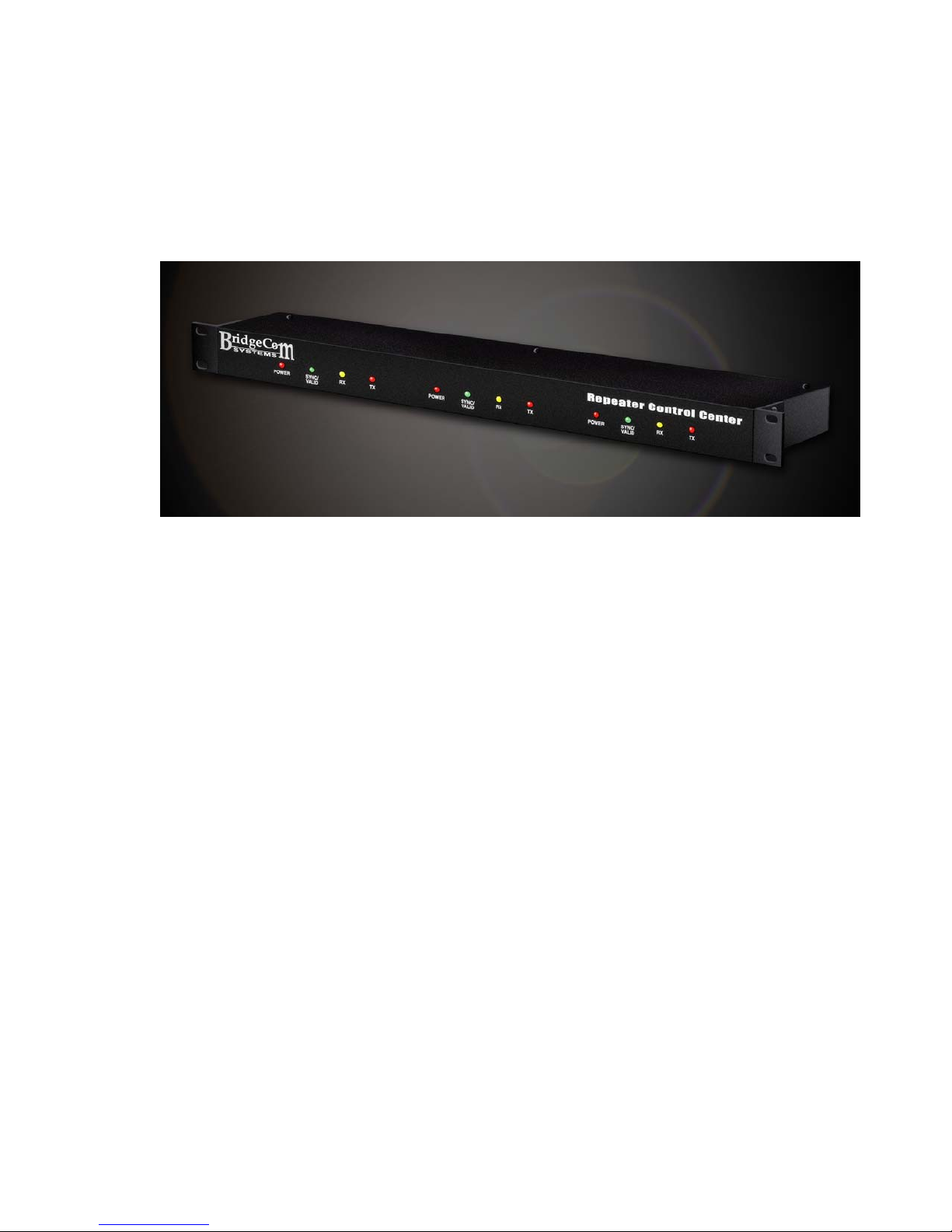
ComLink TL/TL-NET Owner’s Manual
Version 1.6, Aug 2014
Page 2

Copyright 2012 BY
Bridge Embedded Systems, Inc
Version 1.5, January 2012
All rights reserved.
Printed in the United States of America.
LTR is a registered trademark of EF Johnson Corporation
Windows is a registered trademark of Microsoft Corporation
For Technical Support, please contact:
BridgeCom Systems, Inc.
617 Liberty Road
Smithville, MO 64089
Tel: (816)-532-8451
Page 3

TABLE OF CONTENTS
CHAPTER 1: INTRODUCTION ............................................................................................ 4
WELCOME ........................................................................................................................ 4
CHAPTER 2: INSTALLATION ............................................................................................. 5
CHAPTER 3: CONTROLLER AND SYSTEM CONNECTIVITY ................................................ 12
CHAPTER 4: VALIDATION AND AIR-TIME ....................................................................... 13
CHAPTER 5: REMOTE MANAGEMENT ............................................................................... 14
OVERVIEW...................................................................................................................... 14
APPENDIX A: TRUNKING CONTROLLER TROUBLESHOOTING.......................................... 15
WARRANTY AND SERVICE .............................................................................................. 16
FCC STATEMENTS ........................................................................................................... 17
3
Page 4
CHAPTER 1: INTRODUCTION
Welcome
Thank you for purchasing the ComLink TL/TL-NET local and wide-area LTR
repeater controller.
This Owner’s Manual will acquaint you with the features and show you how to
program and interface the TL-NET LTR controller to your repeater system. Every
effort has been made in the preparation of this manual to ensure the accuracy of
its contents. However, please note that one of the many features of the TL-NET
includes upgradable firmware. Firmware upgrades may modify existing features
and/or introduce new features not available at the time of this manual’s
publication. Please read the accompanying documentation with any firmware
upgrade for any changes to this manual’s content.
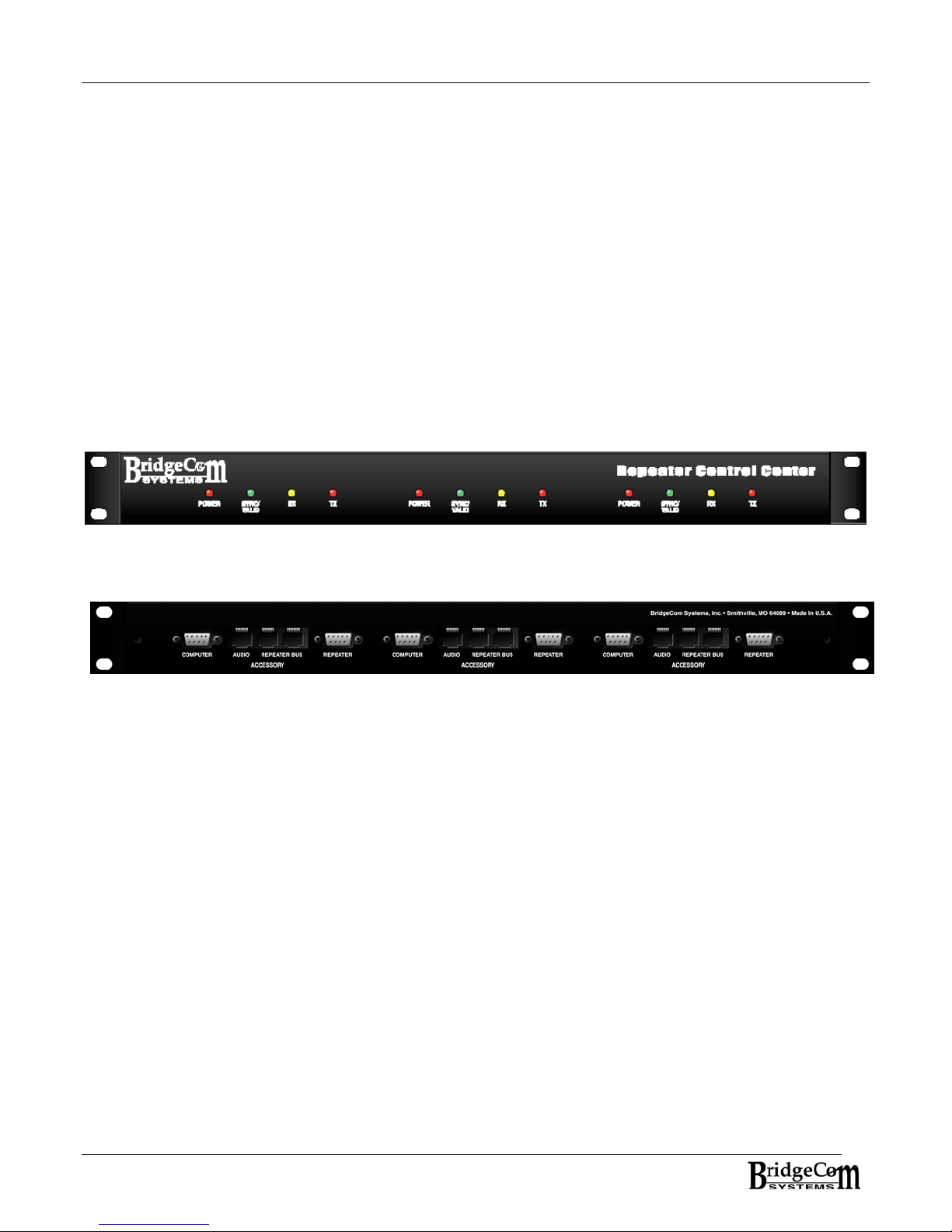
Front View of three controllers in 1U chassis
Rear View of three controllers in 1U chassis
As you read this document, here are KEY POINTS To REMEMBER:
In order for the TL-NET LTR controller designated as the Network Master to operate correctly, it
must have TL-NET mode enabled when connected to a TL-NET Gateway. However, TL-NET mode
must be disabled when programming the controller using the TL Control Manager software. Also,
only the Network Master needs to be in TL-NET mode. If more than one controller is used in the
system, a second controller can be used to program all the controllers while leaving the network
master connected to the TL-NET Gateway. When initializing a controller to a repeater number it
must be connected to the PC and have TL-NET mode disabled.
Only one controller CAN BE the SYNC Master for reliable communications between
controllers and the PC.
In the event you want to adjust a controller not on the repeater bus and does not have
termination jumpers installed, for that controller you’ll need to use a CAT-5e Network
cable to loop the two repeater bus ports back to itself.
4
Page 5
CHAPTER 2: INSTALLATION
Step 1: Repeater Connection
Build a cable to connect the controller to your repeater. The following table indicates the pins for
repeater connecter J32.
J32 – DSUB9 MALE - Repeater Connector Pin-out
Pin 1- GND
Pin 2- COR/COS Input (Active Low) +5V Pull-up
Pin 3- RX Discriminator In – From Repeater RX
Pin 4- TX Audio Out – To Repeater TX Audio
Pin 5- No Connection
Pin 6- 13.8Volts DC Input
Pin 7- TX Data Out – To Repeater TX Data
Pin 8- PTT Out +5V (Active Low)
Pin 9- PTT Out Open Drain – Active Low – Rev C PCB or later.
Step 2: Program the controller
1. Connect the PC to the connector designated as COMPUTER or J31.
2. If you haven’t done so, install the TL-NET Control Manager software. The software is
supported on all Windows operating systems WIN 95,WIN XP, Win 7 and 8.
3. Run the TL-NET Control Manager software.
4. Disable TL-NET mode. This is done by selecting TL-NET from the menu list and selecting
DISABLE.
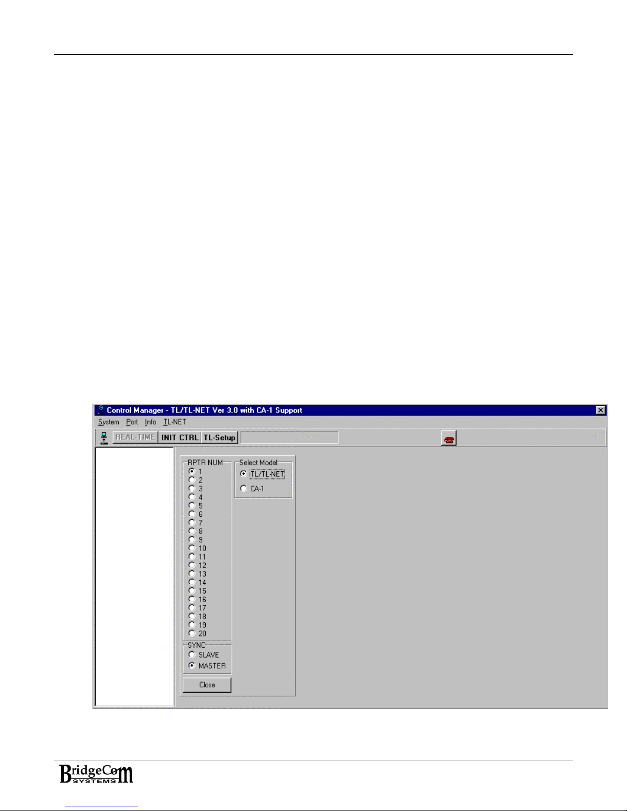
5. If the controller has yet to be assigned a repeater number, select INIT CTRL button from
the task bar. The snapshot below is what you should see.
Init CTRL Repeater Number and SYNC Status Assignment
5
Page 6
6. Select the Repeater Number and SYNC status. The Controller must be programmed to
be either MASTER or SLAVE. NOTE: For proper stable communications between
controllers and the PC, the terminating jumpers (J15-J20) must be installed on at least
one controller attached to the repeater bus. It is also necessary that at least one
controller be assigned the SYNC Master. However, keep in mind, it’s not necessary to
have the PC connected to the SYNC master in order to talk to the repeater controller
system. Press Close when done.
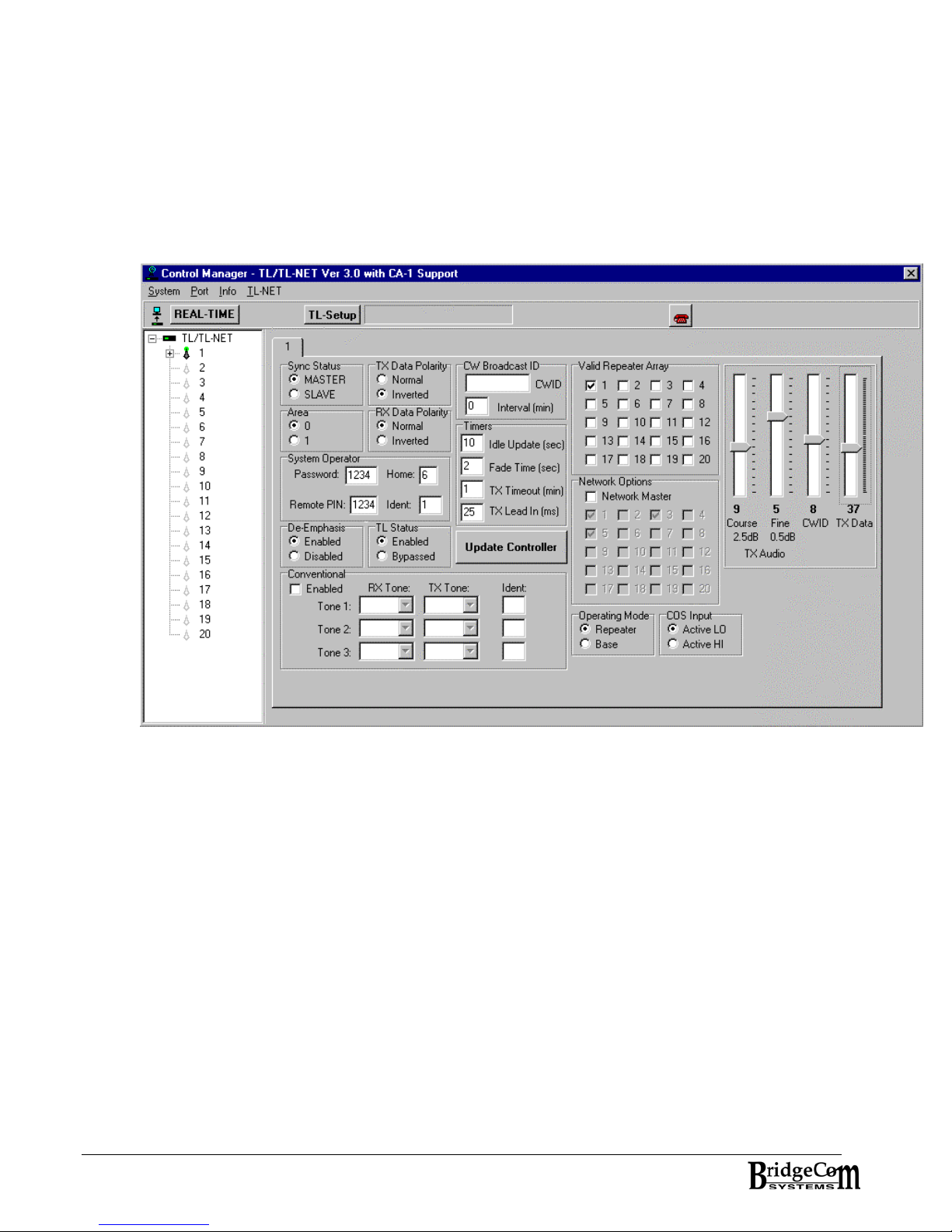
7. Select the Read System Icon from the task bar. Enter “1234” as the default password.
The following screen is seen. Note: Certain settings may be different on your controller.
Controller Settings Tab Sheet
8. Program the settings as required by your system. The following list describes each
parameter:
1. Sync Status – Designates this controller as either MASTER or SLAVE
2. Area – 0 or 1
3. TX Data Polarity – Normal or Inverted
4. RX Data Polarity – Normal or Inverted
5. System Operator –
1. Password – protects unauthorized attempts when reading controller from the
Control manager software
2. Remote PIN – DTMF sequence prior to sending Over the AIR programming
commands
3. HOME and IDENT – SYSOP home and ident used when sending Over the Air
programming commands.
6. De-Emphasis – Selects whether internal deemphasis is enabled or disabled.
7. TL Status – Selects whether the TL-LTR controller is enabled or disabled.
8. CW Broadcast ID – Enter the channel ident to be sent via Morse code. Also enter
how often the channel ident is to be sent.
9. Timers:
6
Page 7

1. Idle Update interval – Duration the controller sends a free repeater telegrams
when the controller is not busy.
2. Fade Timer – Duration the controller will continue to send LTR telegrams after
it fails to decode valid LTR telegrams from the active mobile.
3. TX Timeout – Duration the controller will transmit continuously before keying
down.
4. TX Lead In – How long the controller waits after engaging the repeater PTT
before sending LTR telegrams. Provides a wait time to ensure repeater is on
frequency and can send full LTR telegrams without missing preamble of the
LTR telegram. Check your repeaters requirements.
10. Conventional CSQ/CTCSS – Select the RX and TX tone and Ident Mask Number.
11. Valid Repeater Array: This check box array tells this controller what other
controllers in the system it has permission to trunk calls to. It might be that
even though another controller is in the system, you may not want this particular
controller to trunk calls to it. This feature is good for mixing networked and nonnetworked repeaters. You may not want a networked repeater trunking calls off
to non-networked channels. Also, this feature is nice when you are adding
repeater controllers to the site and have yet to upgrade the mobiles in the field.
12. Network Options:
1. Network Master – Select this checkbox if this controller is to function as the
network master. The network master will be the controller connected to the
TL-NET Gateway’s serial port. Check the only the one controller connected to
the TL-NET Gateway.
2. Network Array – This is a network master feature only. Check each box of all
the TL-NET controllers connected to the TL-NET Gateway’s audio ports. These
will be your network repeaters/controllers.
13. TX Audio Settings: Press the UPDATE CONTROLLER after adjustment is made.
1. Course – adjusts the TX Audio in 2.5 dB step increments.
2. Fine – adjust the TX Audio in 0.5 dB step increments.
3. CW ID – adjust the broadcast ID tone deviation.
4. TX Data – adjusts the TX LTR Data in 0.5 dB step increments.
14. Operating Mode – Sets mode of operation as either Repeater or Base
15. COS (Carrier Operated Switch) Polarity Output – Active Hi or Active LO
16. UPDATE CONTROLLER – Once changes are made, press this button to update the
controllers.
STEP 3: ALIGN THE CONTROLLER
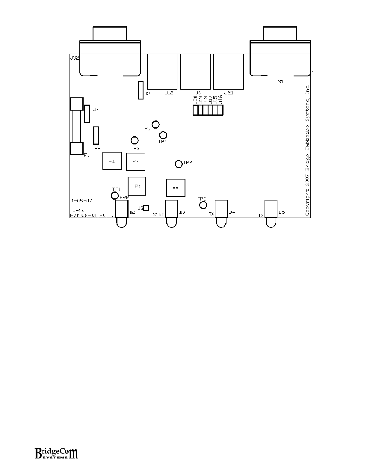
For the next steps, reference the PCB layout Figure (see Figure on next page). You will
need to remove the unit’s cover to access the PCB.
There can be two different sources for the receive audio. One is the local audio coming
from the repeater’s receiver and the other is the Gateway connecting the audio from the
other sites. The local audio from the repeater’s receiver must be tuned first.
Adjust local receive audio first:
1. Program the service monitor for the repeater RX frequency. Inject a full-quieting 1kHz
tone deviating at 3.0 kHz (wide – 25kHz) 2.0 kHz (narrow – 12.5 kHz). Place
voltmeter on DC and put voltmeter probe on TP1. Adjust P1 until TP1 reads 2.5 Volts.
7
Page 8
2. ADJUST RX AUDIO GAIN: P4 adjust the RX Audio Gain from 0 to 1. The purpose of
this adjustment is to reduce the gain in the event the receiver supplies too much signal
for the controller. In most cases, this POT should be set full CW for unity gain (1). If
more gain is needed, the internal audio signal processor will allow for increasing the
signal. If the incoming signal is large, use P4 to adjust the signal measured at TP4 to
1V P-P.
3. RX DATA AC GAIN: Remove the 1 kHz tone from the service monitor. Program the
service monitor to generate a full-quieting 100 Hz tone or LTR Data deviating at 1kHz
(wide – 25 kHz) or 800 Hz (narrow – 12.5 kHz). Place voltmeter on AC and probe on
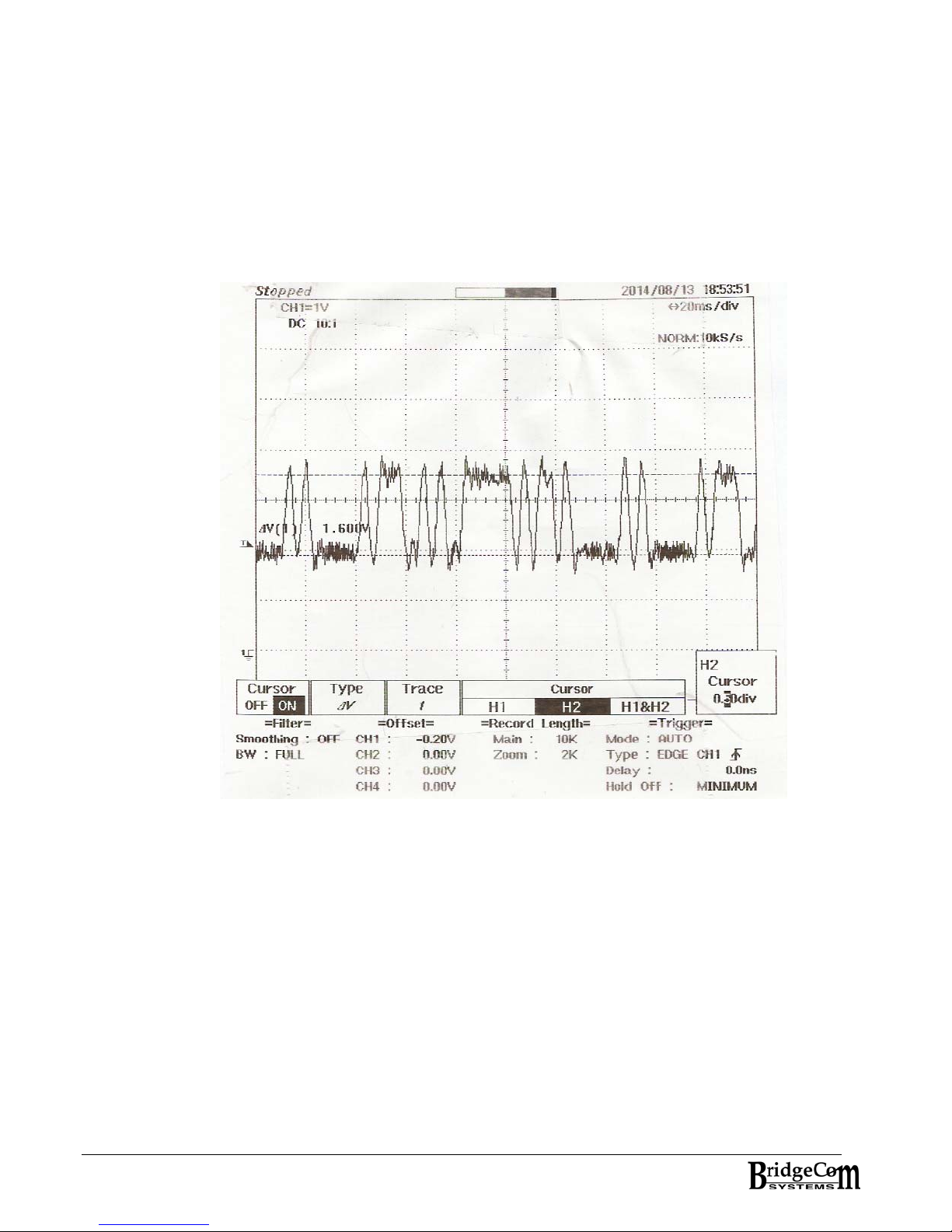
TP2. Adjust P2 until 1.5-1.8 Volts P-P is achieved. See plot of Received LTR Data as
viewed on TP2.
4. RX DATA DC Adjust: Place voltmeter on DC. With probe remaining on TP2, Adjust P1
until ~ 2.5Volts is achieved. Then place probe on TP6 and confirm the DC voltage is
between 2.0 and 3.0 volts
8
Page 9
PCB Layout
5. Gateway audio – Each gateway supports adjustment of the audio volume to/from other
sites. To adjust the audio for a specific channel, you will need to log on to the
gateway’s web site and adjust the RECORD volume.
Adjust Local TX audio:
AC or DC coupling to repeater: J1 and J2 are three terminal jumpers that control the
signal coupling to the transmitter. J1 sets the audio coupling to the transmitter. When the
audio is AC coupled, a 10-uF capacitor is placed in series with the audio. When the audio is
DC coupled it is biased to 2.5Volts. To AC couple the audio to the repeater, place the
jumper on the J1’s two pins towards the repeater connector (J32). J2 sets the data coupling
to the transmitter. When the LTR data is AC coupled, a 220-uF capacitor is placed in series
with the LTR data. When the LTR data is DC coupled it is biased to 2.5Volts. To AC couple
the TX Data to the repeater, place the jumper on J1’s two pins away from the repeater
connector (J32).
J1 – AC or DC couple TX Audio To Transmitter
J2 – AC or DC couple TX Data To Transmitter
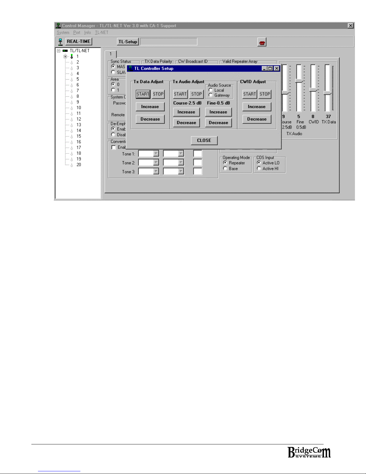
1. Using the TL Control Manager software press the TL-Setup button. The following screen
shot will be displayed.
9
Page 10
TL CONTROLLER SETUP FORM
2. TX DATA ADJUST - With the transmitter connected to the service monitor and on the
proper TX frequency, press the START button under TX Data Adjust. Increase or
decrease the TX Data level until 1 kHz (wide) or 800Hz (Narrow) is achieved. Press
STOP. In the event data cannot go low enough, place shorting block across pins 2 and 3
of J4. Then increase Data level accordingly. Pin1 is towards front of PCB.
3. TX AUDIO ADJUST – Make sure the audio source is Local. With the service monitor in
duplex mode, inject a 1 kHz tone deviating at 3.0 kHz (wide) or 2.0 kHz (narrow). Press
the START button. Adjust the audio setting until 2.0 kHz (wide) or 1.5 kHz (narrow)
achieved on the transmit frequency. Press STOP.
4. CWID Adjust – Press START. Increase/Decrease the setting until 2.5 kHz (wide) or 1.5
kHz (narrow) deviation. Press STOP.
5. AUDIO to Gateway – With the audio source on LOCAL, press the START button under TX
Audio Adjust. With the service monitor, inject a 1 kHz tone deviating at 3 kHz (wide) or
2 kHz (narrow). Using a voltmeter on the AC setting, place the probe on TP3. Adjust P3
until 200mV is achieved. Press STOP.
6. AUDIO From Gateway – All other controllers at other sites should be sending audio to
their respective gateways at 200mV. Therefore, it is recommended the audio from the
gateway to the controller be adjusted from the gateway’s web server.
Alignment is now complete. Using a radio programmed for the controller, attempt to
handshake with the repeater. If handshake attempts are unsuccessful, check the following
symptoms and possible solutions:
Repeater fails to respond to handshake attempts:
• Make sure you have the selected channel programmed for COS output enabled active low.
• Make sure controller and radio’s Repeater Number and Area Bit are the same.
• Also, make sure the controller is aligned to ‘see’ the data. Inspect TP2.
• Make sure the controller is ‘SYNCED’
10
Page 11

Radios won’t complete handshake:
• Make sure TX Data polarity is correct for radios in the system.
• Make sure TX Data levels are adequate for the respective channel spacing.
Once a successful handshake is complete, check to confirm the Local and Network audio levels are
all correct to your liking. REMEMBER: If a controller is the Network Master it must be in
TL-NET mode for the system to properly communicate with other sites. The Network
Master must be connected to the Gateway’s serial port.
In summary, here is a list of the adjustment pots (P) and test points (TP)
Potentiometers: Description
P1 RX DC Data Adjust (0-5Volts DC)
P2 RX Data Level Adjust (0-20)
P3 Audio to Gateway Level Adjust (0-10)
P4 RX Audio Level Adjust (0-1)
Test POINTS: Description
TP1: RX Data/Tone AC and DC Level
TP2 RX Data/Tone AC gain
TP3 Audio to Gateway
TP4 Audio level from Receiver
TP5 Audio from Gateway
TP6 Dynamic DC RX Data Adjust
JUMPERS Description
J1 AC or DC coupling selector for Voice
J2 AC or DC coupling selector for DATA
J3 PTT Test Point – Active High
J4 TX Data Attenuator – Rev C PCB and later
J6 & J12 REPEATER BUS
J15-J20 Bus Terminator shorting block header
J21 AUDIO connector to TL-NET Gateway
J31 COMPUTER Connection
J32 REPEATER Connection
11
Page 12
Chapter 3: Controller and System Connectivity
In a trunking system the TL controllers communicate to each other through the repeater bus. The repeater
bus uses the RS-485 standard to communicate. RS-485 requires terminating resistors. Terminating resistors
reduce the transmission line effects caused by the signals propagating over long distances. To enable the
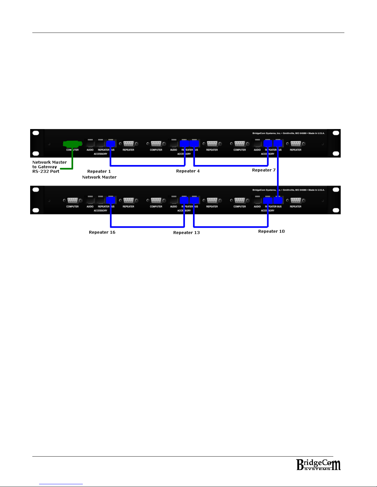
terminating resistors, place shorting blocks across Jumpers J15-J20 on at least one controller in the system.
Daisy-chain the controllers using straight-through cat-5e networking cable or RJ-11 8 conductor telephone
cable. It’s advisable to keep the cabling between controllers as short as possible. See system example
below.
REMEMBER: Jumpers must be installed on the ends of the bus in the system. For the system example
below, jumpers would be placed on controller 1 and controller 16. For proper communication between PC and
the controller, the controller must have jumpers installed, be in a system with a controller that has jumpers
installed, or have a CAT5e network cable looped back to both repeater bus connectors.
SYSTEM EXAMPLE
Each controller’s audio port is connected to a Gateway audio port. In the above example, the
audio from Repeater 1 would connect to Gateway audio port 1, Repeater 4 to Gateway audio port
2, etc. The controller designated as the network master is to be connected to the Gateway’s
RS-232 COM port. In the above graphic, Repeater 1’s controller is the network master.
12
Page 13
Chapter 4: Validation and Air-Time
Each controller’s group idents can be validated/invalidated from three different sources: The TL
Control Manager software, remotely through DTMF key sequences, and through the TL-NET
Gateway from the TL-NET Gateway’s web server. This section deals with managing group idents
from the TL Control Manager software.
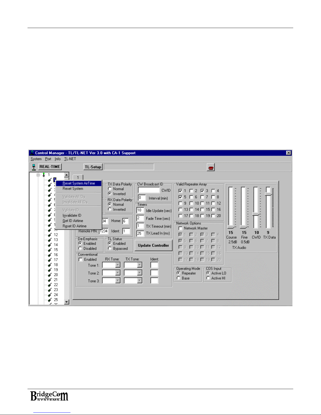
Place the cursor in the Treeview on the left of the form. Right-click the mouse to bring up the popup menu or press F2. Depending on whether a controller node or group ident node is selected will
indicate which options are available. While on a controller node, you have the option of
validating/invalidating all idents for this channel. When on a group ident node, you have the option
of validating or invalidating the group ident. It is not possible to invalidate the SYSOP Home-Ident
used for remote programming. In addition, you can view that particular group ident’s air time and
reset it. NOTE: When validating/invalidating idents, you must perform this option when all the
controllers are attached to the repeater bus. This will ensure all controllers in the system are made
aware of the validation status. After performing the operation, you can read the system to confirm
the results. The TL LTR controller validates a call as the handshake attempt is made. This means
the ident is checked the moment a radio attempts to access the controller. If the ident is invalid,
no access is granted.
TL Control Manager with TreeView pop-up menu options
13
Page 14

CHAPTER 5: REMOTE MANAGEMENT
Overview
The TL-NET LTR controller supports the remote management of IDENTS and repeater controllers. IDENTS can
be validated and invalidated over the air. Repeater Controllers can be validated/invalidated over the air. You
can also reset a particular controller over the air. You must set up a specific HOME-ID combination for system
operator usage in the TL Control Manager Software. All controllers in the system must be programmed with
the same HOME-ID combination, and 4-digit PIN. As long as all controllers in the system have the same 4digit PIN and SYSOP HOME-IDENT, it does not matter what controller you handshake with.
• VALIDATING/INVALIDTING IDENT: Upon successful handshake with the system using the
system-operator HOME-ID, the command sequence is as follows: First 4 digits are the PIN followed by
two digit HOME, followed by three digit IDENT, followed by a 1 for Validate or 0 for Invalidate. A '#' is
then pressed to cause the task to execute:
For Example: You’ve chosen 2135 as the PIN and your selected HOME-ID is 05-002. You want to
enable a new customer by given them ID 140 and HOME them on repeater 12. Once handshake is
complete using 05-002, key in the following:
[2][1][3][5] [1][2] [1][4][0] [1] [#]
The HOME-ID should now be validated. Verify by handshaking with the system.
To invalidate HOME-ID 12-140, upon successful handshake, key in the following:
[2][1][3][5] [1][2] [1][4][0] [0] [#]
Confirm by observing the radio is now unable to handshake with the system.
• VALIDATE/INVALIDATE ALL IDENTS: You can validate or invalidate all idents for a particular
controller. For Example, to invalidate all idents on controller 12, key in the following:
[2][1][3][5] [1][2] [0][0][0] [4] [#]
To validate all idents of controller 12:
[2][1][3][5] [1][2] [0][0][0] [5] [#]
• VALIDATING/INVALIDATING REPEATERS - VALID REPEATER ARRAY: The CS-540TL supports a
feature called: valid repeater array. This feature allows you to set up a controller to only trunk calls
off to specific ‘valid’ repeaters. This feature comes in handy for the following reasons: Lets say you
have just added a fourth channel to your trunking system and you have yet to update all the radios
using this system. During operation it might be these radio’s home channel will trunk them off to this
new fourth channel. Unfortunately, the radios don’t know about this new channel and will this prevent
the call indicating a busy system. To prevent this from happening, the home channel can exclude
this new channel by making it invalid. Once you’ve upgraded the fleet, you can ‘validate’ this new
channel by permitting the controllers to trunk to it.
For example, you’ve added repeater 15 to the system. Repeater 5 doesn’t have repeater 15 in its
valid repeater array and so won’t trunk calls to it. To make repeater 5 aware of repeater 12, enter the
following after successful handshake with the system:
[2][1][3][5] [0][5] [0][1][2] [2] [#]
To take repeater 12 out of 5’s valid repeater array, key in the following:
[2][1][3][5] [0][5] [0][1][2] [3] [#]
Bear in mind, the repeater to be validated/invalidated is a three-digit field.
RESET A PARTICULAR CONTROLLER: For example, to reset controller 12
•
[2][1][3][5] [1][2] [0][0][0] [6] [#]
14
Page 15

Appendix A: Trunking Controller Troubleshooting
1. Repeater fails to respond to handshake attempts:
• Make sure you have the selected channel programmed for COS output enabled active low.
• Make sure controller and radio’s Repeater Number and Area Bit are the same.
• Also, make sure the controller is aligned to ‘see’ the data. Inspect TP2.
2. Radios won’t complete handshake:
• Make sure TX Data polarity is correct for radios in the system.
• Make sure TX Data levels are adequate.
3. My PC is not communicating with the controller:
• Make sure you have first assigned a repeater number to the controller.
• Make sure at least one controller in the system has repeater bus terminating resistors installed.
• Make sure the controller is not in TL-NET mode.
• Make sure the system has SYNC.
4. Controller won’t SYNC:
• Make sure at least one controller in the system is programmed as the MASTER.
• Make sure controller TL-STATUS is not in BYPASS mode.
• Check Cat5e cable quality.
• Check to see if at least one controller in system has the repeater bus resistor terminating jumpers
installed.
5. Home channel is not trunking calls off to the GOTO channels:
• Make sure the home channel has the GOTO channels checked in the valid repeater array. Also, make
sure the proper controller is has its check box checked.
6. Controller is not Powering up:
• Check cable to repeater or power source.
• Open unit and check internal fuse. If blown, replace with 1.5A fuse.
• Check reverse polarity protection Diode D6.
15
Page 16

WARRANTY AND SERVICE
Limited Warranty
This product is warranted by BridgeCom Systems, Inc. to be free of defects in materials and
workmanship for a period of two years from the date of purchase. If a defective part causes
this product to operate improperly during the two-year warranty period, we will service it to the
original owner free of charge if shipped to BridgeCom Systems at the owner’s expense. This
warranty does not apply to any parts damaged due to improper use or violation of instructions.
It does not extend to damage incurred by misuse or abuse, unauthorized modifications, natural
causes such as lightning, fire, floods, and other such catastrophes; nor to damage caused by
environmental extremes, such as power surges and/or transients, theft, or accidents.
All warranties must be performed at BridgeCom Systems, Inc. No credit will be given for
unauthorized repair work attempted by the customer.
BridgeCom Systems, Inc. will repair or replace the equipment and return to the customer
freight pre-paid, within the continental United States. Equipment found not to be defective will
be returned at the customer’s expense, and it will include the cost to ship, test, and return the
equipment.
Equipment returned for repair must have a return merchandise authorization (RMA) number.
To obtain an RMA contact our Technical Support Department at (816)-532-8451 or email
listed on the outside of the shipping container.
Ship all returns to BridgeCom Systems, Inc. 617 Liberty Rd. Smithville, MO 64089 Attn:Repair
Out of warranty repairs and service charges are billed at the current hourly rate plus parts.
PRICES ARE SUBJECT TO CHANGE WITHOUT NOTICE.
This document contains information proprietary to Bridge Embedded Systems, Inc. and
BridgeCom Systems, Inc. Its contents may not be reproduced, in whole or in part, without
express written permission from either Bridge Embedded Systems, Inc. or BridgeCom Systems,
Inc.. The information is provided “AS IS” without warranty of any kind, either expressed or
implied. Bridge Embedded Systems, Inc. or BridgeCom Systems, Inc. does not assume any
liability for damages. Technical information and specifications in this document are subject to
change without notice.
. All returned equipment must have the RMA number
16
Page 17

FCC Statements
This equipment has been tested and found to comply with the limits for a Class B digital device,
pursuant to part 15 of the FCC Rules. These limits are designed to provide reasonable protection
against harmful interference in a residential installation. This equipment generates, uses and can
radiate radio frequency energy and, if not installed and used in accordance with the instructions,
may cause harmful interference to radio communications. However, there is no guarantee that
interference will not occur in a particular installation. If this equipment does cause harmful
interference to radio or television reception, which can be determined by turning the equipment off
and on, the user is encouraged to try to correct the interference by one or more of the following
measures:
-- Reorient or relocate the receiving antenna.
-- Increase the separation between the equipment and receiver.
-- Connect the equipment into an outlet on a circuit different from that to which the receiver is
connected.
-- Consult the dealer or an experienced radio/TV technician for help.
17
 Loading...