

Page 1

BCH-220 Owner’s Manual
By BridgeCom Systems, Inc.
Page 2

Copyright 2015 BY
Bridge Embedded Systems, Inc
Version 1.1, Oct 2015
All rights reserved.
Printed in the United States of America.
Windows is a registered trademark of Microsoft Corporation
For Technical Support, please contact:
BridgeCom Systems, Inc.
102 NE State Route 92 Highway, Suite C
Smithville, MO 64089
Tel: (816)-532-8451
2
Page 3

TABLE OF CONTENTS
CHAPTER 1: INTRODUCTION ............................................................................................ 5
WELCOME ........................................................................................................................ 5
SPECIFICATIONS ............................................................................................................ 5
CHAPTER 2: UNPACKING AND PREPARATION .................................................................. 6
PARTS LIST ...................................................................................................................... 6
CHARGING THE BATTERY ....................................................................................................... 7
BATTERY CHARGER INDICATOR ................................................................................................ 7
LCD ICONS ...................................................................................................................... 8
CHAPTER 3: FEATURES AND OPERATION.......................................................................... 9
KEYPAD OVERVIEW: ............................................................................................................ 9
CHAPTER 4: QUICK START – GET ME ON THE AIR!.......................................................... 10
SETTING RX FREQUENCY: ................................................................................................... 10
PROGRAMMING FOR USE WITH A 220 MHZ REPEATER:................................................................... 10
OFFSET FOR TX.............................................................................................................. 10
DUPLEX OPERATION...................................................................................................... 10
RX CTCSS/DCS ENTRY .................................................................................................... 10
TX CTCSS/DCS ENTRY..................................................................................................... 11
CHAPTER 5: BASIC OPERATION...................................................................................... 12
WORKING MODES ............................................................................................................. 12
1)FREQUENCY MODE (VFO) ............................................................................................... 12
2)MEMORY MODE............................................................................................................ 12
3)FM MODE.................................................................................................................. 12
4)MENU MODE ............................................................................................................... 12
CHAPTER 6: HOW-TO FUNCTION GUIDE:........................................................................ 13
● MEMORY MODE CHANNEL RECALL / VFO FREQUENCY ENTRY ......................................................... 13
● STORING A CHANNEL TO MEMORY ....................................................................................... 13
● DELETING A CHANNEL FROM MEMORY ................................................................................... 13
● SETTING SQUELCH (SQL) ............................................................................................. 14
● CHANGING POWER LEVEL HIGH/LOW POWER ........................................................................... 14
● CHANGING FREQUENCY STEP SIZE ....................................................................................... 14
● CHANGING FREQUENCY DIRECTION FOR DUPLEX OPERATION........................................................ 14
● PROGRAMMING THE SIDE KEY AND TOP KEY......................................................................... 14
● START CHANNEL SCAN ..................................................................................................... 15
● RX CTCSS/DCS .......................................................................................................... 15
●TX CTCSS/DCS ........................................................................................................... 15
CHAPTER 7: MENU ITEMS ............................................................................................... 16
00 – BEEP .................................................................................................................... 16
01 - LIGHT................................................................................................................... 16
02 – KEY LOCK ............................................................................................................. 16
03 – BATTERY SAVE ...................................................................................................... 17
04 - TOT – TIME OUT TIMER .............................................................................................. 17
05 - VOX SWITCH ......................................................................................................... 17
06 - VOX LEVEL ............................................................................................................ 17
07 - POWER ON MESSAGE .................................................................................................. 18
08 – ROGER ................................................................................................................. 18
3
Page 4

09 - APO / AUTOMATIC POWER OFF ...................................................................................... 18
10- OFFSET.................................................................................................................. 18
11 - W/N – WIDE BAND / NARROW BAND............................................................................... 18
12 - SCAN MODE .......................................................................................................... 19
13 - SCAN ADD............................................................................................................. 19
14 – VOICE .................................................................................................................. 20
15 – ANI (AUTOMATIC NUMBER IDENTICATION)......................................................................... 20
16 - TOP KEY................................................................................................................ 20
17 - PTT ID .................................................................................................................. 20
18 - RESET .................................................................................................................. 20
APPENDIX A: CTCSS AND DCS TABLES ........................................................................... 22
AVAILABLE STANDARD /NON-STANDARD CTCSS TONES ................................................................. 22
APPENDIX B: SIDE KEY AND TOP KEY TASK LIST .......................................................... 23
WARRANTY AND SERVICE .............................................................................................. 24
FCC STATEMENTS ........................................................................................................... 25
4
Page 5

CHAPTER 1: INTRODUCTION
Welcome
Thank you for purchasing the BCH-220 hand-held two way radio. The goal of the BCH-220 is to
provide a cost-effective, feature rich hand held radio for users of the 220 amateur radio spectrum.
This Owner’s Manual will acquaint you with the features and operation of the BCH-220. Every
effort has been made in the preparation of this manual to ensure the accuracy of its contents.
Carefully read this manual in order to properly operate the radio before use.
SPECIFICATIONS
General
Number of Channels: 199
Working Voltage: 7.4 V DC
Channel Spacing: 25kHz/12.5kHz
Weight w/Battery & Ant 230g
Frequency Range: 222.0 – 224.995 MHz
Dimensions (W x H x D): 58.5 mm x 110.5 mm x 35.6 mm
Frequency Stability: +/- 1.5 ppm
Operating Temperature: -4° F to +122° F (-20° C to +50° C)
Battery Type: Li-Ion
Antenna Connector: SMA Male
Antenna Impedance: 50Ω
TRANSMITTER
RF Output High Power: 5 Watts / Low Power: 2 Watts
Maximum Deviation:
Antenna Connector: SMA Male
Antenna Impedance: 50Ω
+/- 5kHz (25 kHz) +/- 2.5 kHz (12.5 kHz)
In our on-going commitment to quality specifications are subject to change without notice.
BCH-220
5
Page 6
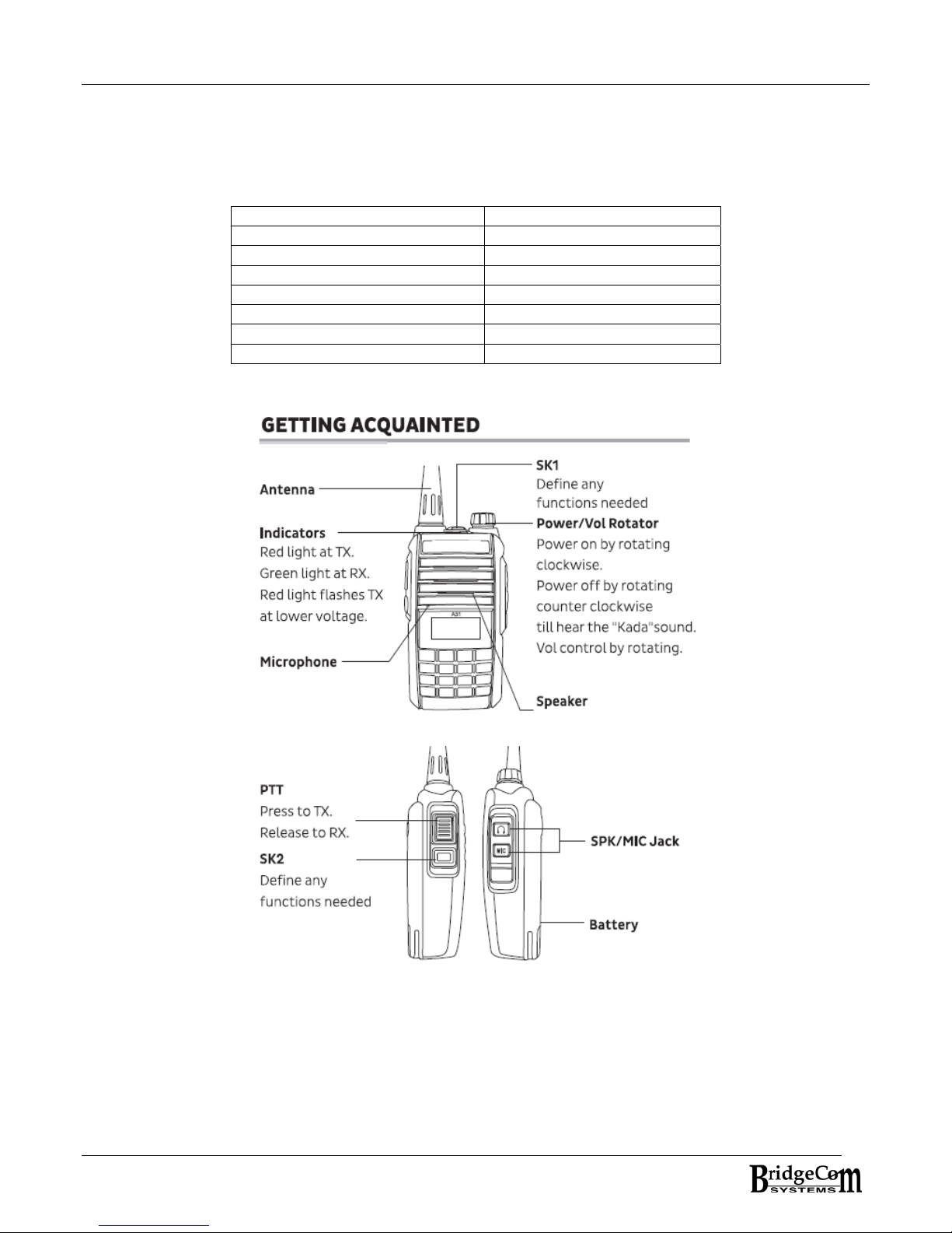
CHAPTER 2: Unpacking and Preparation
We recommend that you identify the items listed in the following packing list. If you find that all
the items are not present, please contact us.
Parts List
Item Quantity
Rubber Antenna 1
Li-ion Battery Pack 1
Desktop Charger 1
Power Adapter 1
Belt Clip 1
This user’s Manual 1
Hand Strap 1
6
Page 7

Charging the Battery
The battery is not completely charged at the factory, therefore the battery will need to be charged before
using the radio. After two to three charge / discharge cycles, the operating capacity will
increase to its normal capacity.
1. Fasten the battery pack to the back of the radio.
is powered OFF.
To charge the battery:
Note: Before charging, it is advised the radio
2. Using the plied power adaptor, plug the output terminal of the power adapter in the DC jack behind
the charger base. The charger LED will indicate ORANGE for about 2 seconds then go out.
3.
Place the radio into the charger cradle. When charging, the LED indicator will light RED. Once the
battery is fully charged the charger LED will turn GREEN. It normally takes about 5 hours to
completely charge an empty battery.
Battery Charger Indicator
Operation Indicator
Power Connected Orange LED on 2 seconds then goes out
No battery NONE
Charging RED solid
Fully charged GREEN solid
Fault Condition (Over temp,
short circuit, or over discharge)
Red LED flashes
7
Page 8

LCD Icons
1
Channel/Menu
2
3
4
5
6
7
8
9
10
11
12
13
Key Lock
Last Digits at Frequency
DTMF
DCS
CTCSS
Battery
FM Radio
Narrow Band
Low Power
VOX
Scan
Function
8
Page 9

CHAPTER 3: FEATURES AND OPERATION
Switching Power On and Off and adjusting audio volume level
1. With a fully charged battery, connect the antenna to the top of the radio’s antenna jack.
2. Rotate the POWER/VOL knob clockwise to turn on the radio. A power up alert will be heard
and the current DC supply voltage will be indicated. After about 2 seconds, the display will
resume normal operation and display the current operating frequency.
3. To increase/decrease the audio volume level, rotate the POWER/VOL knob.
4. To power down the radio, rotate the POWER/VOL knob fully counter clockwise until clicked
and the display goes dark.
After powering up, the radio defaults to the VFO operating mode and the default receive (RX)
frequency is displayed.
Keypad Overview:
The BCH-220 sports a 16 button keypad for operating the radio. From the keypad, you will be able
to program the radio for how you want it to operate.
9
Page 10

CHAPTER 4: QUICK START – GET ME ON THE AIR!
Setting RX Frequency:
To enter the desired RX frequency, simply key the frequency into the radio using the keypad. For
example: To enter 224.140 MHz.
Key in 2 – 2 – 4 – 1 – 4 - 0 and the radio will confirm programming with a ‘good’ beep.
Programming for use with a 220 MHz repeater:
In North America, the general split for most 220 repeaters is 1.6 MHz. Therefore, you’ll need to
enter the OFFSET from the RX frequency so when you PTT the radio it will apply the OFFSET to the
RX frequency and Transmit on the correct Frequency as set by the OFFSET. To enter the OFFSET,
follow this procedure:
OFFSET for TX
Press and . Choose OFFSET by pressing until the LCD displays OFFSET. Then
press
receiving. Once the desired OFFSET is on the LCD, press-and-release the
Another quicker way to program OFFSET is to manually enter the frequency. For example, to enter
1.6 MHz, simply key 0 0 1 6 0 0. The value will automatically be entered. Press
setting and back to previous item or press
DUPLEX OPERATION
Now that the OFFSET is programmed, the radio needs to be told whether it’s a positive, negative,
or no OFFSET. This is done by using the DUP key. Cycling through the DUPLEX settings is done by
using the DUP key. Pressing
DUPLEX, NEGATIVE DUPLEX, or POSITIVE DUPLEX. After each
and see if the result is NO DUPLEX, POSITIVE, or NEGATIVE. Sequence until the desired DUPLEX
setting is achieved.
RX CTCSS/DCS Entry
1. Press
2. Press
3. Press
4. Press
and to choose desired frequency difference between transmission and
to store the value.
to cancel setting and back to main menu.
and then 5DUP will cycle through the DUPLEX settings of NO
and 5DUP press, key the radio
, then press 7 R.T. If not set previously, the LCD will display 67.0.
to switch between CTCSS and DCS: OFF CTCSS DCS N OFF
to switch DCS Polarity: DCS N DCS I
to step to the desired CTCSS/DCS or directly input the desired CTCSS/DCS.
For example: 102.5Hz for CTCSS.
a. If necessary press
b. Key in: 1,0,2,5
to switch to CTCSS.
to cancel
c. Press
will be displayed.
5. If at any time there’s an entry error, press
10
to store the setting. A ‘good’ beep will be emitted and the RX Frequency -
to cancel the entry and the radio will revert
Page 11

back to displaying the previous CTCSS/DCS tone. To completely cancel the entry process,
press-and-release
mode.
6. The TX CTCSS/DCS Entry will automatically be set to the same RX CTCSS/DCS Entry.
. You cannot set the RX signaling when the radio is in MEMORY
TX CTCSS/DCS Entry
1. Press , then press 8 T.T, If the RX signal wasn’t set previously, the LCD will display will
default to 67.0.
For TX CTCSS/DCS entry, see above steps 2-6 as indicated for RX CTCSS/DCS entry.
You should now be able to communicate radio-to-raio or on your local 220 MHz repeater! The
remainder of this manual will acquaint you with many of the features of the BCH-220. Enjoy!
11
Page 12

CHAPTER 5: Basic Operation
TX
1. Using the monitor button on the left side of the radio, monitor the radio to ensure there is no
one transmitting on the chosen channel.
2. Press PTT and face the microphone before talking. The LED should turn RED indicating TX.
To ensure good voice quality, the distance between your mouth and the microphone should
be between 2.5 and 5 cm.
3. Release PTT to put radio back in receive (RX).
4. When using the earphone and VOX active, users can enjoy hands-free talking. Also users
can activate the IVOX function which doe not use the earphone.
RX
1. Upon power up, the radio defaults to a pre-programmed or default RX Frequency.
2. When radio is receiving a valid call, the speaker un-mutes and the green LED lights.
3. Certain conditions may be required for the radio to un-mute and receive. For example,
proper CTCSS/DCS signal decode might be required in order for the radio to un-mute. In
addition, the receiving signal must be strong enough to break the squelch (SQL) setting.
4. CTCSS/DCS signaling is a special squelch protocol and can help to ignore unwanted calls on
the channel. CTCSS/DCS is programmed on a per channel basis. To communicate using
CTCSS/DCS, other radios must have the same signaling in their radios.
Working Modes
1)Frequency Mode (VFO)
To change to VFO mode press and hold while turning the radio power on. In this mode
you can use the keypad to enter the desired RX Frequency on which you would like to
communicate. You can then step up/down in frequency by pressing the
The step size up and down is determined by STEP programming. While in VFO mode, you
can press the
step up/down through the memory channels and the channel frequencies are displayed.
key and this will convert to a quasi VFO/MEMORY mode where you can
keys.
2)Memory Mode
To change to MEMORY mode press and then turn radio power on. In this mode you
can press the
the channels will be displayed.
keys to step through the pre-programmed channels. The names of
3)FM Mode
The BCH-220 supports an FM radio. To change to FM Radio mode press and .
While in this mode, you can press
FM stations, press
Mode press-and-hold
or + . To scan pre-programmed FM Stations, while in FM
.
to change the FM radio frequency. To scan the
4)Menu Mode
To enter Menu mode, press and numeric key 9. Press to choose desired item.
More details please refer to “Menu Operations”.
12
Page 13

Chapter 6: HOW-TO Function GUIDE:
● Memory Mode Channel recall / VFO Frequency Entry
1. In Memory mode or Memory/VFO mode, you can input three numbers to change
channels. If the radio has pre-programmed channel numbers assigned then it’s a
matter of enter the 3-digit channel number to recall the channel. If the channel does
not exist, then the current channel is maintained. The following examples illustrate:
To recall: CH1 (KEY 0 0 1), CH98 (KEY 0 9 8), CH123 (KEY 1 2 3)
2. In VFO mode, simply key in the desired RX Frequency. After keying in the 6 digit
frequency, if it’s a valid RX Frequency, the radio will begin receiving. If the
frequency is invalid, the radio will revert back to the previous working frequency.
To enter 224.220 MHz – KEY IN: 2 2 4 2 2 0 – A ‘good’ beep will indicate success.
● Storing a Channel to Memory
Channel frequencies are stored in VFO mode only.
1. While the RX frequency to store is displayed, Press and then press to start the
channel store operation. The word SAVE will be displayed and flash on the screen.
2. Press
also key in the 3-digit channel number.
3. Press
or
to cancel and return to previous frequency screen.
to select which channel number slot to assign to the frequency. You can
to store the channel . A ‘good’ beep will indicate success. Otherwise, press
● Deleting a Channel from Memory
Deleting a channel is done in VFO/Memory mode.
1. To access VFO/Memory mode, press the
upper left corner of the display. Next, turn off unit and then turn unit back on while
holding the
2. Press
and delete ,then press
channel. If there is no channel with frequency value ,radio will exit channel delete and
resume normal operation.
key. The word DEL should begin flashing in the LCD display.
to choose desired deleted channel number or directly input channel number
to confirm. The radio will automatically sequence to the next
key. channel number is displayed in the
13
Page 14

● Setting SQUELCH (SQL)
The purpose of the squelch control is to mute the speaker when no signals are present. With the
squelch level (0-9) correctly set, the speaker will only un-mute when there is a strong signal
present. The higher the squelch level, the stronger the signals must be to un-mute the speaker.
The appropriate squelch level depends on the ambient RF noise conditions.
1. Press
2. Press
3. Press
screen. Press
and then KEY 1 SQL. The LCD will display the current SQUELCH level.
to choose desired SQL level.
to confirm the setting. Press or to cancel and go back to previous
to cancel the setting.
● Changing Power Level High/Low Power
1. Press and then KEY 2 POW. The LCD will display the current TX Power Level.
2. Press
3. Press
screen. Press
to adjust the High/Low power.
to confirm the setting. Press or to cancel and go back to previous
to cancel the setting.
● Changing Frequency Step Size
1. Press and then KEY 4 STEP. The LCD will display the current step size. The step size
options are: 2.5K, 5K, 6.25K, 10K, 12.5K, 15K, 20K, 25K, 30K, 50K, and 100K.
2. Press
3. Press
the setting.(This feature adjustment is only available in VFO/Memory mode )
to choose desired step.
to confirm the setting. Press or to exit the menu. Press to cancel
● Changing Frequency Direction for DUPLEX operation
1. Press and then KEY 3 DUP to toggle the frequency reverse function.
2. Repeatedly sequencing the
settings: No DUPLEX, Positive Duplex, and Negative duplex. There must be an OFFSET
programmed to observe the POSITIVE/NEGATIVE duplex change.
You cannot operate reverse frequency if there is no frequency on the channel.
key and Key 3 DUP KEY cycles through the directional
● Programming the SIDE KEY and TOP KEY
The side key is programmed using the PC BASED programming software. The top key can be set
using the programming software or from accessing the TOP KEY entry in the SET menu item list.
14
Page 15

● Start Channel Scan
1. Press and numeric KEY 6 SCN to start scanning.
2. Press
Scanning in VFO mode, the radio will scan by stepping through the channels as determined
by the programmed frequency step. Scanning in Channel mode will step through all
programmed channels. Scanning in FM Mode, the radio will scan all valid FM Radio
frequencies. In Channel mode, scanning will not activate if radio has less than two
channels.
to change scanning direction during scanning.
● RX CTCSS/DCS
1. Press , then press 7 R.T. If not set previously, the LCD will display 67.0.
2. Press
3. Press
4. Press
For example: 102.5Hz for CTCSS.
a. If necessary press
b. Key in: 1,0,2,5
to switch between CTCSS and DCS: OFF CTCSS DCS N OFF
to switch DCS Polarity: DCS N DCS I
to step to the desired CTCSS/DCS or directly input the desired CTCSS/DCS.
to switch to CTCSS.
c. Press
will be displayed.
5. If at any time there’s an entry error, press
back to displaying the previous CTCSS/DCS tone. To completely cancel the entry process,
press-and-release
mode.
The TX CTCSS/DCS Entry will automatically be set to the same RX CTCSS/DCS Entry. In
addition, the BCH-220 can any non-standard CTCSS tone and DCS code. Simply
key in the desired tone/code.
to store the setting. A ‘good’ beep will be emitted and the RX Frequency
to cancel the entry and the radio will revert
. You cannot set the RX signaling when the radio is in MEMORY
●TX CTCSS/DCS
1. Press , then press 8 T.T. If not set previously, the LCD will display 67.0.
2. Press
3. Press
4. Press
For example: 102.5Hz for CTCSS.
a. If necessary press
b. Key in: 1,0,2,5
c. Press
5. If at any time there’s an entry error, press
back to displaying the previous CTCSS/DCS tone. To completely cancel the entry process,
press-and-release
mode.
The BCH-220 can support any non-standard CTCSS tone and DCS code. Simply key
in the desired tone/code.
to switch between CTCSS and DCS: OFF CTCSS DCS N OFF
to switch DCS Polarity: DCS N DCS I
to step to the desired CTCSS/DCS or directly input the desired CTCSS/DCS.
to switch to CTCSS.
to store the setting. A ‘good’ beep will be emitted and the RX Frequency
will be displayed.
to cancel the entry and the radio will revert
. You cannot set the TX signaling when the radio is in MEMORY
15
Page 16

CHAPTER 7: MENU Items
The BCH-220 supports 19 menu items for setting various parameters that determine the operation
of the radio. This chapter details each of these items and how each item works.
To access the menu list, Press
up, item 00 – BEEP is displayed. During operation, the menu item displayed will be the last menu
item that was displayed when the menu list was exited.
and . If the menu list has not been accessed since power
00 – BEEP
This feature turns the KEY press TONE and POWER ON TONE ON/OFF.
Access BEEP by pressing the
and
store. Press
exit the menu item list.
to choose ON or OFF. Once option is selected, press to confirm and
to cancel setting and go back to the previous menu item or press to
keys until the LCD displays BEEP. Then press
01 - LIGHT
This feature sets the BACK LIGHT status ON/OFF and the ON duration (in seconds) when a
KEY is pressed.
Access LIGHT by pressing the
and to choose ON, 2, 5, 10, 15, 20, 25, or OFF. Store the setting by pressing
to confirm and revert back to the menu list. Press to cancel and revert back to
the previous item or press
to cancel setting and exit the menu item list.
keys until the LCD displays LIGHT. Then press
02 – KEY LOCK
This feature programs the KEY LOCK feature. The KEY LOCK feature allows for locking out
the key pad. The options are: MANU where this option uses the key. The key is
pressed and held to LOCK the keypad. AT 5, AT 10, AT 20, AT 30 lock the key pad after 5,
10, 20, or 30 seconds. Once the keypad is locked it remains locked until the
pressed-and-held with UNLOCK displayed. The radio will not remember the key pad is
locked upon power cycle. ATS 5, ATS 10, ATS 20, ATS 30 locks the key pad after 5, 10, 20,
30 and STORES the setting so the radio remembers the KEY LOCK status upon power cycle.
Access the KEYLOCK feature by pressing the
LOCK.KEY.
ATS 5, ATS 10, ATS 20, ATS 30. Once the selection is made, press
selection and revert back to the menu list. Press
previous item or press
Then press and to choose MANU, AT 5, AT 10, AT 20, AT 30,
to cancel setting and exit the menu item list.
keys until the LCD displays
to store the
to cancel and revert back to the
is
16
Page 17

03 – BATTERY SAVE
The battery save feature decreases the amount of power used when a signal is not being
received and no operations are being performed. This menu item allows for programming
the battery save ratio from 1-1 to 1-10. Where 1-1 is the highest battery consumption, and
1-10 is the lowest battery consumption.
Access battery save by pressing the
and to choose OFF, 1-1/1-2/.../1-10 ratio. Once ratio is selected, press
to confirm and revert back to the menu list. Press
previous item or press
to cancel setting and exit the menu item list.
04 - TOT – Time Out Timer
This function limits how long the user is allowed to PTT before stopping transmit. In the
programming software an alarm can be set to emit an alert prior to time-out-timer
expiration.
Access TOT by pressing the
to choose OFF, 30/.../600 (seconds) r stopping transmission. Once ratio is
selected, press
revert back to the previous item or press
to confirm and revert back to the menu list. Press to cancel and
05 - VOX SWITCH
This function allows for turning ON/OFF the VOX feature. VOX stands for voice activated
transmit.
Access VOX SWITCH by pressing
and to choose OFF or ON. Once VOX ON or OFF is selected, press to
confirm and revert back to the menu list. Press
previous item or press
to cancel setting and exit the menu item list.
06 - VOX LEVEL
This feature allows for setting the audible voice level required to initiate a VOX transmission.
The setting is 1 through 10. Where 1 requires loud voice and 10 is for soft voice. When the
radio is receiving VOX is not available. The programming software allows for programming
VOX Level Compare Value and VOX Delay Time. VOX Delay time helps provide for
proper flow of RX/TX communication. Experiment with this feature to determine optimum
value.
Access VOX LEVEL by pressing
and to choose desired VOX level (1-10). Press to confirm and revert
back to the menu list. Press
to cancel setting and exit the menu item list.
keys until the LCD displays SAVE. Then press
to cancel and revert back to the
keys until LCD displays TOT. Then press and
to cancel setting and exit the menu item list.
keys until the LCD displays VOX.SWI. Then press
to cancel and revert back to the
keys until the LCD displays VOX.LVL. Then press
to cancel and revert back to the previous item or press
17
Page 18

07 - Power On Message
This feature allows for customizing a Power On Message. The options are: NO MSG, DC
Voltage, or Custom Message created using the programming software.
Access Power On Message by pressing
Then press
back to the menu list. Press
to cancel setting and exit the menu item list.
and to choose OFF, DC, or MSG. Press to confirm and revert
to cancel and revert back to the previous item or press
08 – ROGER
This feature allows for turning on/off the ‘ROGER’ beep after transmitting. The volume level
of the ‘ROGER’ beep is determined by the setting of the volume control knob.
Access the ROGER item by pressing
press
menu list. Press
setting and exit the menu item list.
and to choose ON or OFF. Press to confirm and revert back to the
to cancel and revert back to the previous item or press to cancel
09 - APO / Automatic Power Off
The APO setting will cause the radio to automatically turn off power if there’s no operation
during the programmed interval. The radio can be powered up by simply pressing any key.
The programmed time interval is OFF, and 1 to 24 hours.
Access the APO item by pressing
and to choose OFF, 1H…24H for the power off timing interval. Press to
confirm and revert back to the menu list. Press
previous item or press
to cancel setting and exit the menu item list.
keys until the LCD displays APO. Then press
10- OFFSET
OFFSET is used to program the difference from the RX and TX frequency when the radio is
used to communicate through a repeater.
Choose OFFSET by pressing
to choose desired frequency difference between transmission and receiving . The
up and down presses will step through using the step size setting. Another quicker way to
program OFFSET is to manually enter the frequency. For example, to enter 1.6 MHz, simply
key 0 0 1 6 0 0. The value will automatically be entered. Press
back to previous item or press
until the LCD displays OFFSET. Then press and
to cancel setting and back to main menu.
11 - W/N – Wide Band / Narrow Band
The W/N setting is used for setting the radio to either WIDE or NARROW band operation.
Choose the W/N menu item by pressing
and to choose WIDE or NARR. Press to confirm and revert back to the
keys until the LCD displays PON.MSG.
keys until the LCD displays ROGER. Then
to cancel and revert back to the
to cancel setting and
until the LCD displays W/N. Then press
18
Page 19

menu list. Press to cancel and revert back to the previous item or press to cancel
setting and exit the menu item list.
12 - SCAN MODE
The Scan Mode menu item allows setting the type of scanning used by the radio. The
scanning modes used by the BCH-220 are as follows:
Time Mode (TO): The radio stops scanning after detecting a signal for approximately 5
seconds. Prior to the 5 seconds expiration, the radio will remember the channel and
continue to scan. When the 5 seconds has expired and the signal is still present, the radio
will stop and rest on the scanned channel.
Carrier Mode (CO): The radio stops scanning when a signal is detected and remains on the
same frequency until the signal drops out.
Search Mode (SE): The radio stops at the pre-programmed frequency or channel when
detecting a signal.
The radio scans through the frequencies in the programmed step size.
The PC based programmer allows for setting the delay time between RX and Scanning. This
timer sets how long the radio remains on a channel prior to resuming scan.
The PC based programmer allows for setting the delay time between the end of TX and
resuming Scan
The PC based programmer also allows for setting the Scan Start Beep on/off and Scan Light
on/off.
Choose the SCAN MODE menu item by pressing
Then press
back to the menu list. Press
to cancel setting and exit the menu item list.
13 - SCAN ADD
For use in MEMORY mode, the SCAN ADD feature allows you to add or delete memory
channels from the scan list. This feature does not work in VFO mode.
You must be in MEMORY Mode and on the specific memory channel when using SCAN ADD.
Choose the SCAN ADD menu item by pressing
Then press
channel. Press
revert back to the previous item or press
If adding the channel the SCN icon will displayed. If deleting the channel, the SCN icon with
disappear.
until the LCD displays SC.MOD.
and to choose SE, TO, or CO. Press to confirm and revert
to cancel and revert back to the previous item or press
until the LCD displays SC.ADD.
and to choose ADD to add the channel or DEL to delete the
to confirm and revert back to the menu list. Press to cancel and
to cancel setting and exit the menu item list.
19
Page 20

14 – VOICE
The radio supports voice prompts upon numeric key presses and power up. This menu item
allows for turning this feature on/off and having voice prompts emitting in either English or
Chinese.
Choose the VOICE menu item by pressing
press
back to the menu list. Press
to cancel setting and exit the menu item list.
and to choose OFF, ENG, or CHS. Press to confirm and revert
to cancel and revert back to the previous item or press
15 – ANI (Automatic Number Identication)
The ANI menu item allows for turning on/off the decode and display ANI during RX.
Choose the ANI menu item by pressing
until the LCD displays ANI. Then press
and to choose ON or OFF. Press to confirm and revert back to the
menu list. Press
setting and exit the menu item list.
to cancel and revert back to the previous item or press to cancel
16 - TOP KEY
The TOP KEY menu item configures what task pressing the TOP KEY will perform. This
feature can also be programmed with the PC Based Programming software. See Appendix
B for available tasks.
Choose the TOP KEY by pressing
to choose one of the items listed in the Appendix B table. Press to confirm
and revert back to the menu list. Press
or press
to cancel setting and exit the menu item list.
and LCD displays TOP.KEY. Then press and
to cancel and revert back to the previous item
17 - PTT ID
The PTT ID menu item allows for chosing when the pre-programmed PTT ID is sent during
PTT. The PTT ID can be sent at the beginning of the transmission (BOT), end of the
transmission (EOT), or both (BOTH). The various parameters for sending DTMF PTT ID are
setup using the PC based programming software.
Choose the PTT ID by pressing
to choose OFF, BOT, EOT, or BOTH. Press to confirm and revert back to the
menu list. Press
setting and exit the menu item list.
to cancel and revert back to the previous item or press to cancel
and LCD displays PTT.ID. Then press and
18 - RESET
The RESET menu item allows for initializing the radio’s settings to default for either VFO or
MEMORY mode. When chosing VFO, all settings are reset except memory channels. FULL
resets the entire radio.
until the LCD displays VOICE. Then
20
Page 21

Choose the RESET by presing and LCD displays RESET. Then press and
to choose VFO or FULL. Press to execute and revert back to the menu list.
Press
to cancel and revert back to the previous item or press to cancel setting
and exit the menu item list.
21
Page 22

APPENDIX A: CTCSS and DCS Tables
Available standard /non-standard CTCSS Tones
1-67.0 14-103.5 27-159.8 40-199.5
2-69.3 15-107.5 28-162.2 41-203.5
3-71.9 16-110.9 29-165.5 42-206.5
4-74.4 17-114.8 30-167.9 43-210.7
5-77.0 18-118.8 31-171.3 44-218.1
6-79.7 19-123.0 32-173.8 45-225.7
7-82.5 20-127.3 33-177.3 46-229.1
8-85.4 21-131.8 34-179.9 47-233.6
9-88.5 22-136.5 35-183.5 48-241.8
10-91.5 23-141.3 36-186.2 49-250.3
11-94.8 24-146.2 37-189.9 50-254.1
12-97.4 25-151.4 38-192.8
13-100.0 26-156.7 39-196.6
Available DCS CODES
023 071 143 225 266 356 452 532 664
025 072 145 226 271 364 454 546 703
026 073 152 243 274 365 455 565 712
031 074 155 244 306 371 462 606 723
032 114 156 246 311 411 464 612 731
036 115 162 245 315 412 465 624 732
043 116 165 251 325 413 466 627 734
047 122 172 252 331 423 503 631 743
051 125 174 255 332 431 506 632 754
053 131 205 261 343 432 516 645
054 132 212 263 346 445 523 654
065 134 223 265 351 443 526 662
22
Page 23
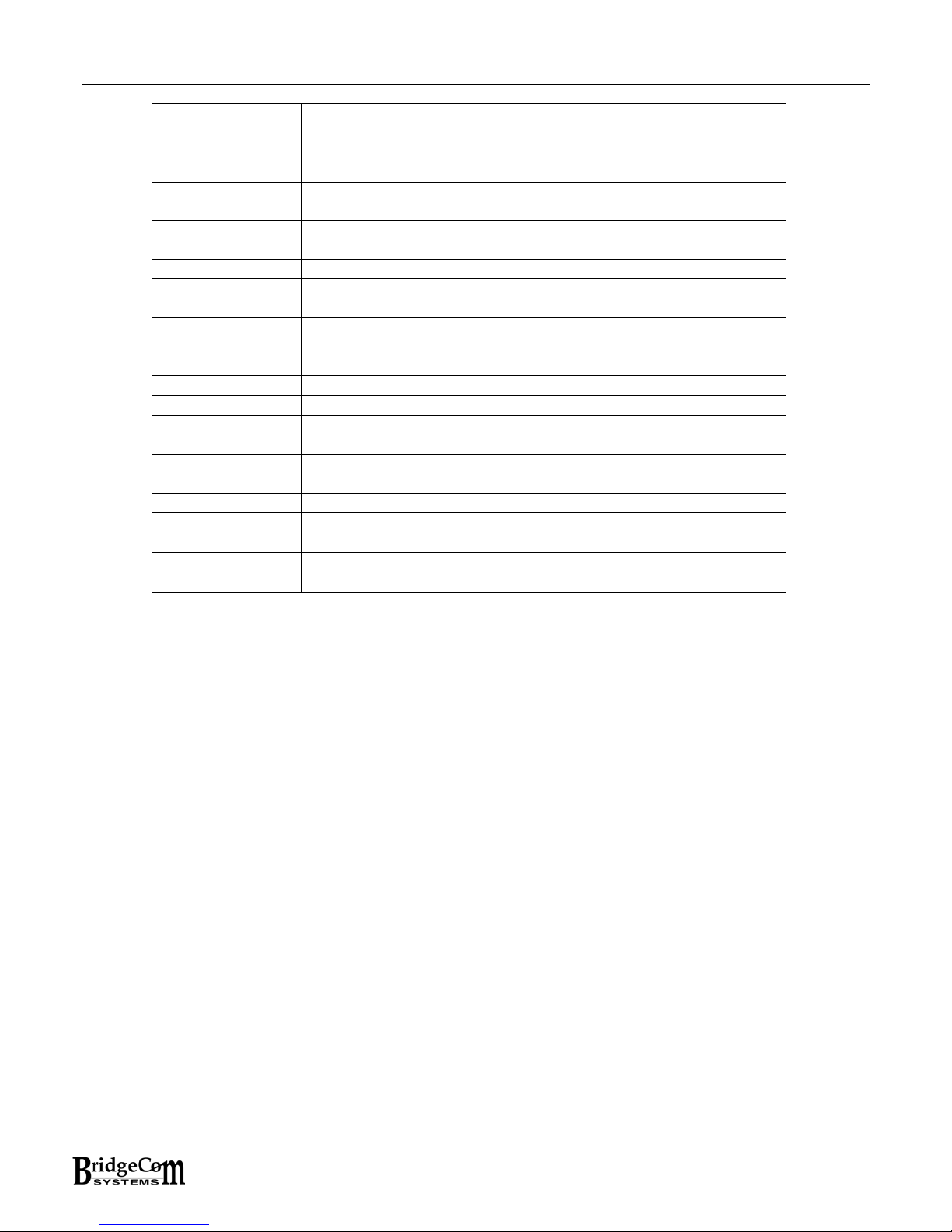
Appendix B: Side Key and Top key Task list
OFF No function available
DIAL
CALL Choose desired number in the pre-programmed list to
SCAN Starts/Stops scanning VFO / Memory channels. Press any
VOX Turn on/off VOX
MONITOR Stop/Start monitor of CTCSS or DCS while radio when
POWER Toggle High/Low power
ALARM Turn on emergency call function. Press PTT to turn off
DTMF IN Input DTMF code, then press PTT to send out DTMF code .
FM RADIO Turn on/off FM radio
FIR CH Quick jump to First channel 1
SEC CH Quick jump to Second Channel 2
SQL OFF Function like a monitor button. Defeats SQUELCH. Toggles
VFO-CH Toggle between VFO and Memory Mode
LED LED Switch on/off
SQL MON During press, momentary SQUELCH defeat.
1750Hz
DIAL is applicable for choosing pre-set code to call
someone by with a pre-programmed DTMF sequence. Press
“Dial” or PTT then press “dial” to send DTMF code.
make. Press 0-9 to choose desired list .
key except [▲] / [▼] to quit scanning .
receiving carrier. Radio will un-mute.
emergency call.
ON/OFF.
Press the side-key to send 1750 Hz signal and release to
stop sending .
23
Page 24

WARRANTY AND SERVICE
Limited Warranty
This product is warranted by BridgeCom Systems, Inc. to be free of defects in materials and
workmanship for a period of one year from the date of purchase. If a defective part causes
this product to operate improperly during the two-year warranty period, we will service it to the
original owner free of charge if shipped to BridgeCom Systems at the owner’s expense. This
warranty does not apply to any parts damaged due to improper use or violation of instructions.
It does not extend to damage incurred by misuse or abuse, unauthorized modifications, natural
causes such as lightning, fire, floods, and other such catastrophes; nor to damage caused by
environmental extremes, such as power surges and/or transients, theft, or accidents.
All warranties must be performed at BridgeCom Systems, Inc. No credit will be given for
unauthorized repair work attempted by the customer.
BridgeCom Systems, Inc. will repair or replace the equipment and return to the customer
freight pre-paid, within the continental United States. Equipment found not to be defective will
be returned at the customer’s expense, and it will include the cost to ship, test, and return the
equipment.
Equipment returned for repair must have a return merchandise authorization (RMA) number.
To obtain an RMA contact our Technical Support Department at (816)-532-8451 or email
listed on the outside of the shipping container.
Ship all returns to:
BridgeCom Systems, Inc.
Attn:Repair
102 NE State Route 92 Hwy
Suite C
Smithville, MO 64089
Out of warranty repairs and service charges are billed at the current hourly rate plus parts.
PRICES ARE SUBJECT TO CHANGE WITHOUT NOTICE.
This document contains information proprietary to Bridge Embedded Systems,
Inc. and BridgeCom Systems, Inc. Its contents may not be reproduced, in
whole or in part, without express written permission from either Bridge
Embedded Systems, Inc. or BridgeCom Systems, Inc.. The information is
provided “AS IS” without warranty of any kind, either expressed or implied.
Bridge Embedded Systems, Inc. or BridgeCom Systems, Inc. does not assume
any liability for damages. Technical information and specifications in this
document are subject to change without notice.
Changes or modifications to this device not expressly approved by Bridgecom Systems could
voice the user’s authorization to operate this device.
. All returned equipment must have the RMA number
24
Page 25

FCC Statements
Warning and Compliance Statement:
This device complies with part 15 of the FCC Rules. Operation is subject to the following two
conditions: (1) This device may not cause harmful interference, and (2) this device must accept
any interference including received interference that may cause undesired operation.
WARNING: Modification of this device to receive cellular radiotelephone service signals is
prohibited under FCC ruiles and Federal Law.
25
 Loading...