

BrickHouse Security FT 6200 User Manual
Installation Guide
GuardFT 6200
Commercial Vehicle Productivity and Security
The Guardian 6200 is a high-performance beacon designed for commercial vehicle applications that require location
based services including productivity and security. It is ideally suited to installations in delivery and service fleets as
well as public safety, mass transportation, utility, and off-road or construction vehicles.
Security features include vehicle theft detection and recovery as well as a means of connecting optional auxiliary
sensors and panic buttons anywhere within the vehicle.
Kit Contents
• GPS Beacon device
• Combined GPS/GPRS antenna
• Wiring harness
• Mounting bracket and hardware
For additional installation information please refer to the Installation Best Practices document available through the Resource Center in
your Dealer Portal.
Tools/Supplies Required
• Wire cutters / wire strippers
• Voltmeter (multimeter)
• Soldering iron / solder
• Electrical tape
• Plastic cable ties
• Screw drivers
• Wrenches/sockets
• In-line fuse holder
• 2-Amp fuse
1 Install Antennas
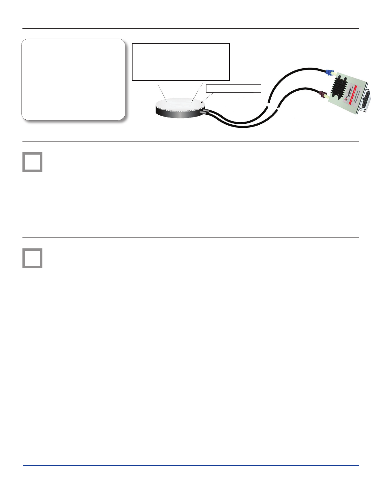
The Guardian 6200 comes with a combined GPS/GPRS
antenna module. It is to be installed in a location where the
GPS performance will be optimum. The integrated adhesive
patch will allow easy attachment to a window or nonmetallic panel.
Determine the best location for the GPS Antenna
• If there is not a suitable flat mounting surface on which
to stick the integrated adhesive patch, affix the antenna
module in place with a caulking type adhesive or plastic
tie wraps.
• Coil and secure any loose or extra lengths of antenna
cables - do not allow antenna cables to kink.
• The antenna is to be installed inside the vehicle – it is not
waterproof or weatherproof.
• The top side of the antenna module (identified by the
peel-and-stick adhesive patch) must have a clear signal
path to as much of the sky as possible.
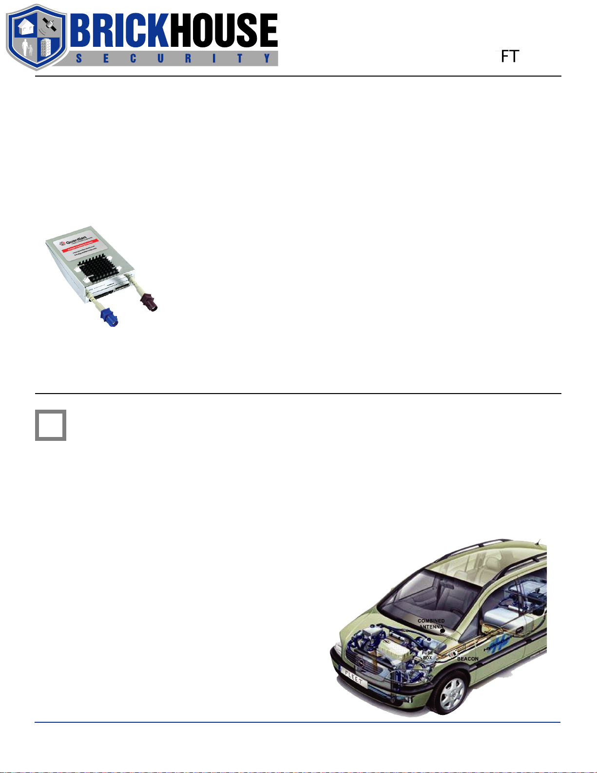
• If the installation is not required to be covert, an ideal
location is on the front windshield glass.
• For covert installations, an ideal location is under the
dashboard, as high and close to the front windshield as
possible (see diagrams).
• If installing in a car, the antenna can usually be mounted
on the rear window or in the trunk, under the rear deck,
as close to the rear window as possible.
Copyright © 2006 Guardian Mobile Monitoring Systems, Inc. All rights reserved.
www.guardianmms.com
Installation Guide
FT 6200
• Signals will penetrate upholstery,
carpet, plastic dashboards, etc.,
but not metal panels or brackets
• Signals will penetrate window glass
but not metallic tinted windows or
painted edges of windows
• Radio antenna or defrost wires
embedded in glass may degrade
signals
For best performance, the
adhesive side of the antenna
should face the sky through the
area of least signal blockage
THIS SIDE UP
COMBINED GPS/GPRS ANTENNA
2 Beacon Installation Position
• Determine beacon installation position but do not fasten it
in place until all wiring is complete.
• Determine the best location for the beacon – a strong flat
surface that can be drilled to accommodate the mounting
screws is ideal. Any spot where the beacon can be
fastened in place with plastic cable ties is suitable.
Peel and Stick Adhesive Patch
• Under a seat is often a suitable location for beacon
installation. Be sure it is not close to any heat sources or
areas that experience moisture or vibration.
• Visibility of the indicator LED will be useful for testing
and troubleshooting. Adequate space for wiring must be
available at both ends of the beacon.
3 Connect Power & Ignition Sense
The 6200 power harness has two wire bundles each containing 4 wires. The Power Bundle contains the 12V
(white), Ground (brown), and Ignition Sense (yellow) wires, plus an unused green wire. The Power Bundle is
wrapped in black jacketing. The second bundle is the I/O Bundle. The I/O Bundle contains the Panic (black) and
Auxiliary (white) wires, plus red and green output wires. The I/O Bundle is wrapped in grey jacketing.
All connection points and wire colors documented in this section reference the Power Bundle.
Notes:
• Connect the wiring harness to all the vehicle’s connection
points before attaching the harness to the beacon.
• If wiring harness wires need to be extended, use the
same grade wire and solder the extension wire on, then
insulate with heat shrink tubing or electrical tape.
• Ensure that no wires are routed near heat sources.
Power Connection Instructions
• Connect the brown (ground) wire to battery negative
or the vehicle chassis – this wire MUST be connected
first, before the power or ignition sense wires. Be sure
the grounding screw is not painted or coated with an
insulating material.
• With the vehicle’s ignition turned off, use a voltmeter to
assist in finding a suitable, uninterruptible 12 Volts power
connection point – directly to the vehicle’s battery may be
best. Connect the white (power) wire to this point through
an in-line 2-Amp fuse (optional – but highly recommended).
Ignition Sense Connection
• Find a source of 12 Volts that is switched on and off with
the ignition key. This connection should produce 12 Volts
when the vehicle is ON and 0 Volts when the vehicle is
OFF. Connect the yellow (ignition sense) wire to this point.
• Ensure that any wires in the wiring harness that are not to
be connected do not come in contact with power, ground,
or any other voltage. Insulate them with electrical tape.
BrickHouseSecurity.com
 Loading...