

Page 1

Easy Installation Guide
Megapixel Day & Night
Bullet Network Camera
OB-500Af Series
English
Page 2
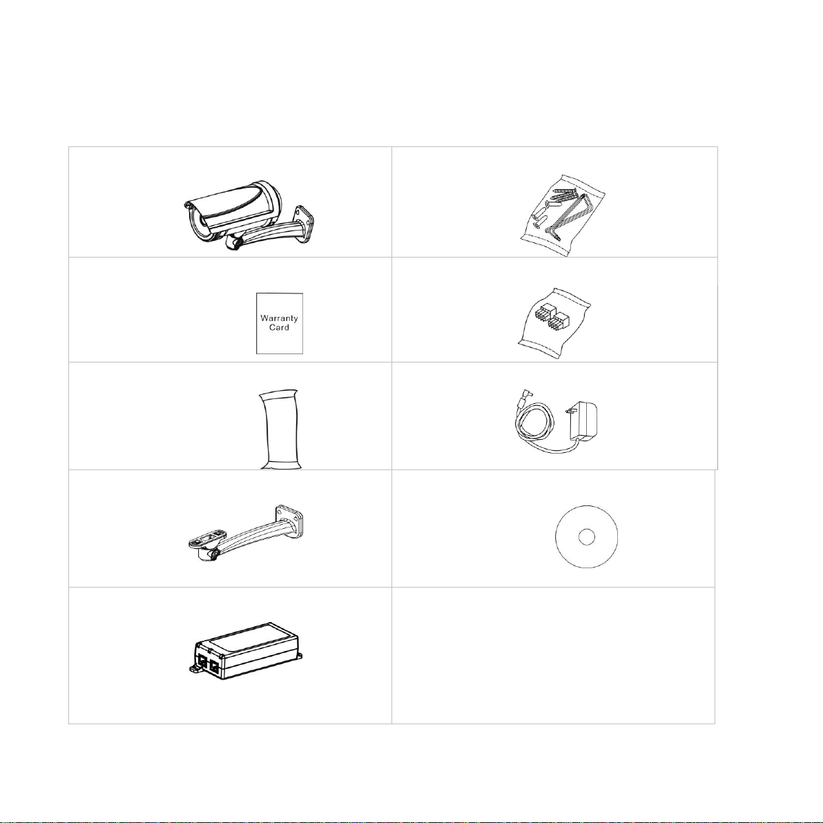
a. Network Camera
b. Screw bag
c. Warranty Card
d. Terminal Block
e. Dry Bag
f. Power Adapter(Optional)
g. Bracket
h. Product CD
i. POE (Optional)
Step 1.Package Contents
Please check to make sure the product package contains all the accessories listed below.
1
Page 3
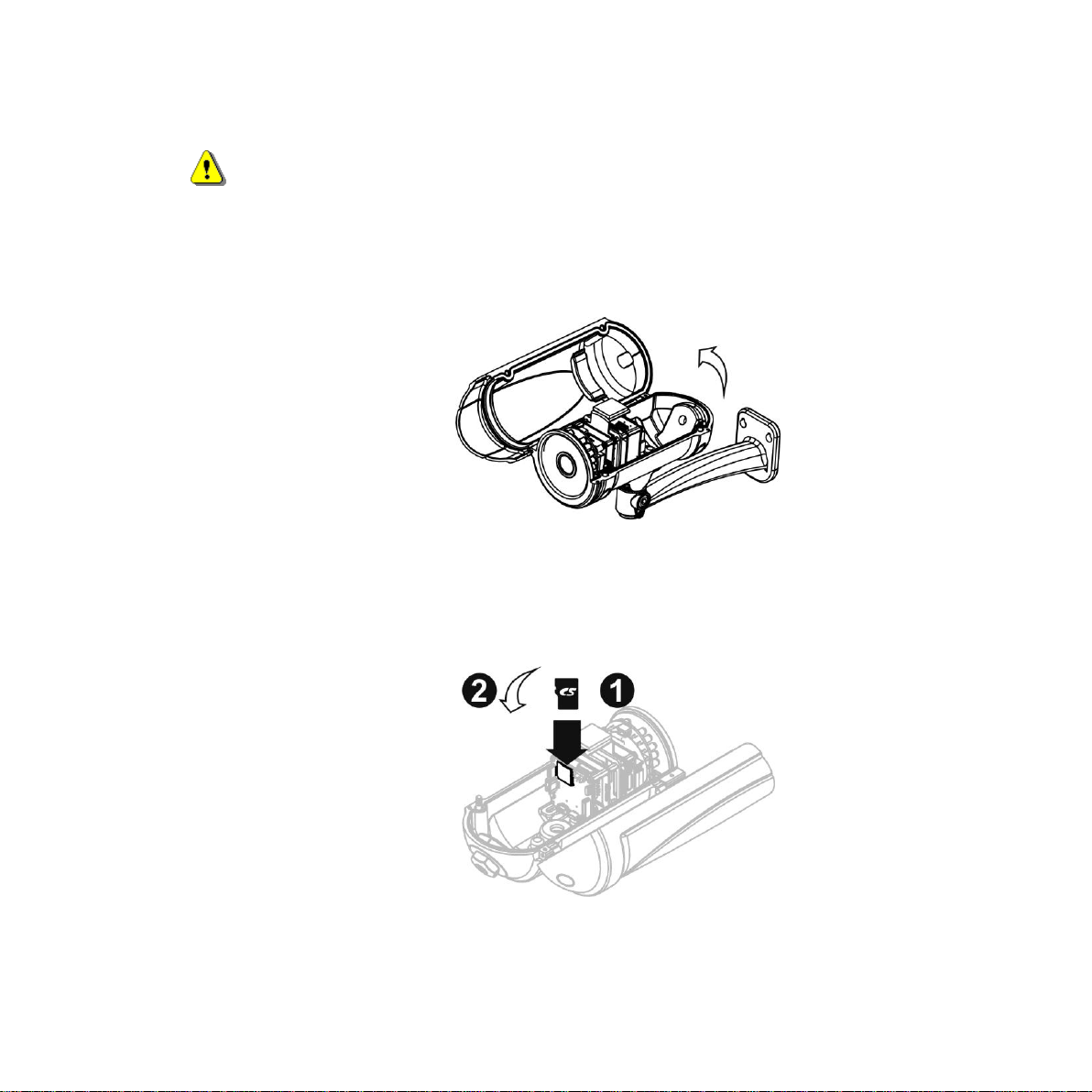
Step 2.Hardware Installation
WARNING - Do not mount the camera on a soft material. The camera may fall and be
damaged.
A. Micro-SD/SDHC Card
a. Remove the top case from the Bullet Camera.
b. (1)Insert the Micro SD/SDHC card into their respective slots.
(2) Reattach the Lens cover and secure the cover to the top of the camera device using two
screws.
B. Bracket Installation
2
Page 4
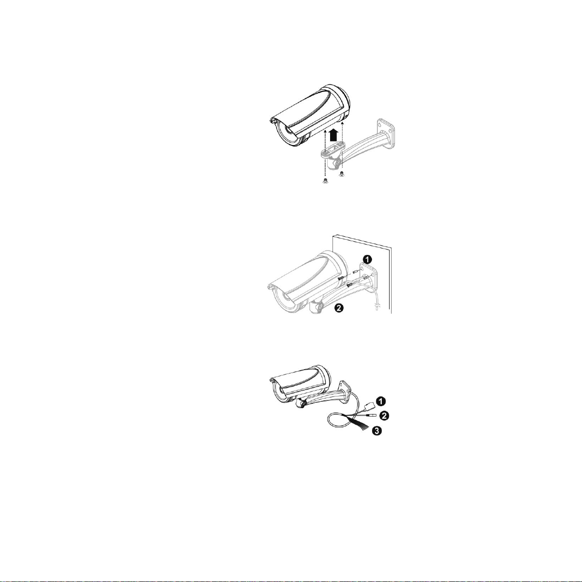
Use the screws to lock the bracket along with the Bullet housing.
C. Wall Installation
a. Drill three holes into the wall and (2) hammer the supplied plastic anchors into the three holes.
(3) Use a screwdriver and the supplied screws to secure the plate to the wall.
b. Connect (1) the POE cable; (2) DC12 Power Connector, (3) Line In/Out, DIDO, RS485 cable;
with the camera. Refer to “Chapter 3” for more details installation information.
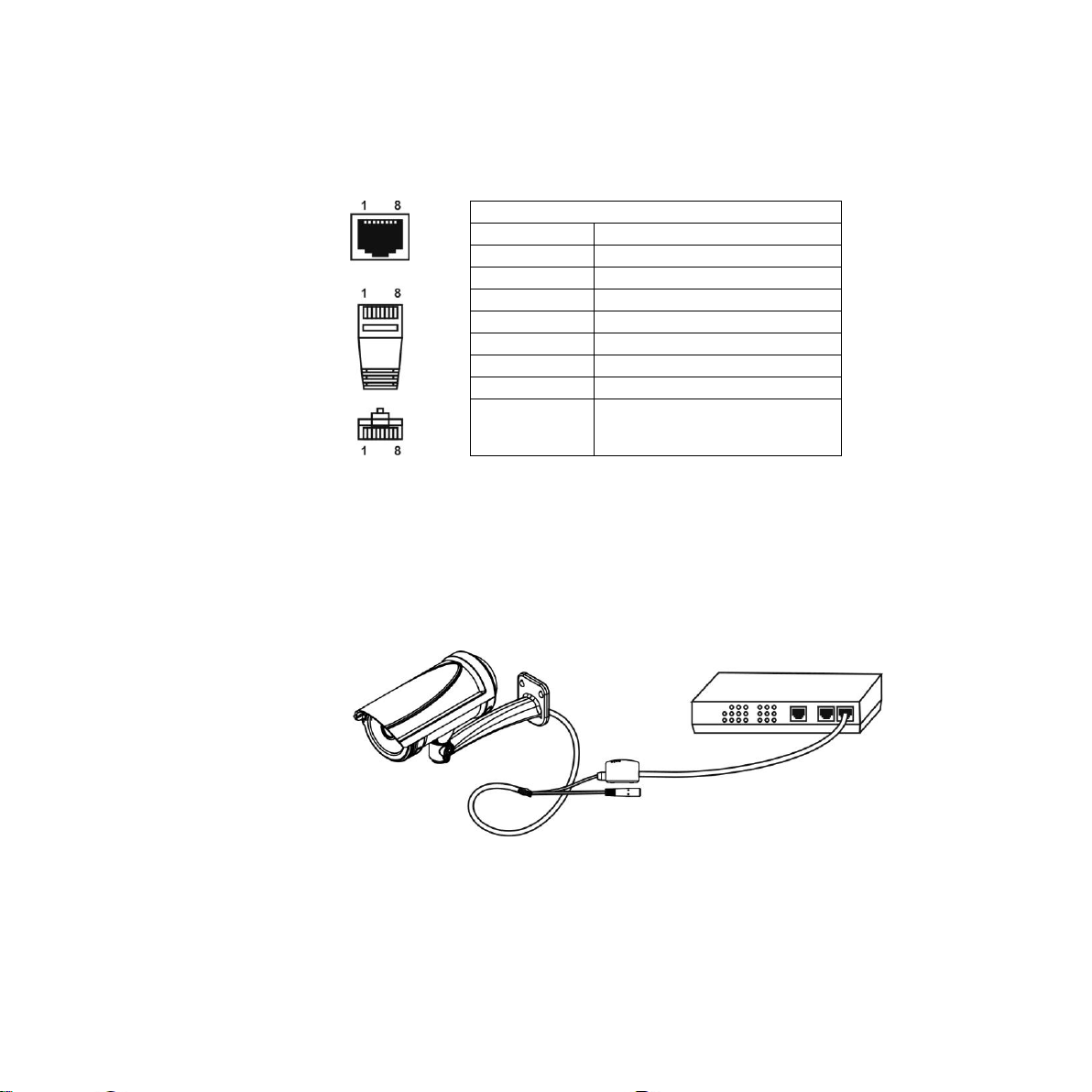
Step 3. PoE Connection
For the Power over Ethernet connection, construct the PoE cable using the pin definitions of
3
Page 5
RJ45 Connector
Pin No.
Function
Pin 1
Transmit Out+ (Tx+)
Pin 2
Transmit Out- (Tx-)
Pin 3
Receive In+ (Rx+)
Pin 4
DC 48V
Pin 5
DC 48V
Pin 6
Receive In- (Rx-)
Pin 7
48V_GND
Pin 8
48V_GND
the RJ45 connector below and refer to step 5 for instructions on how to install the Water Proof
Connector. Once the PoE cable has been constructed using the waterproof connector, pass
the RJ-45 cable from the camera through the bracket and connect it to the PoE cable.
4.1 Camera Connection
The Bullet Series is DC12V and PoE compliant, so there are two options for connecting the camera to
a power and Ethernet source. The camera can either be connected to a PoE-enabled switch or a
non-PoE switch.
a. If using a PoE-enabled switch:
i. Use a single Ethernet cable to connect the camera to the PoE-enabled switch.
b. If using a non-PoE switch:
4
Page 6
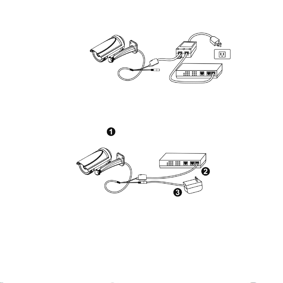
i. Use a standard RJ-45 cable to connect the camera to a PoE Injector.
ii. Use a standard RJ-45 cable to connect the PoE Injector to the non-PoE switch.
iii. Use a standard power cable to connect the PoE Injector to a power outlet.
If using the DC12V for the power Supply. The RJ45 cable will be data transmission.
Step 4. Install the EasyConfig Software
Insert the CD into the CD-ROM, and follow the instructions of the InstallShield Wizard to finish
installation.
5
Page 7
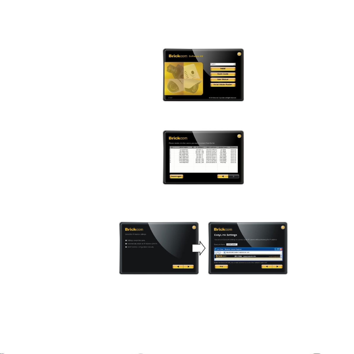
Step 5.Launch EasyConfig
Launch the EasyConfig software, and click on the camera from the survey list to connect.
Follow the EasyConfig software to configure the camera’s IP address and EasyLink
TM
settings.
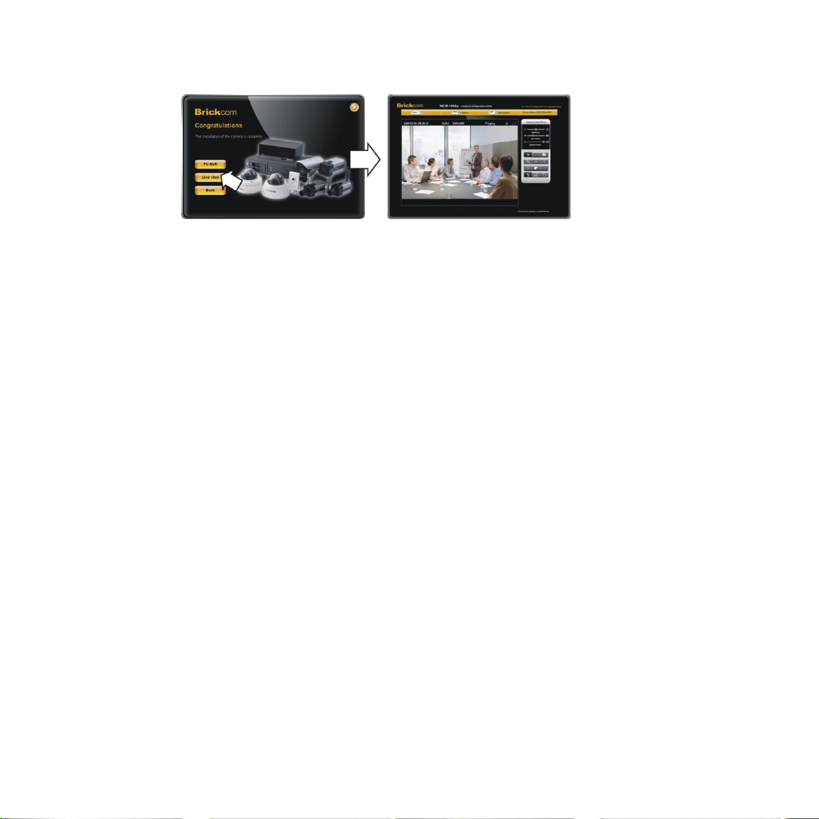
Step 6.Installation Completed
Click <Live View> to view the live video feed of the network camera.
6
Page 8
7
 Loading...