

IP Camera
Quick Installation Guide
Megapixel Cube series
1
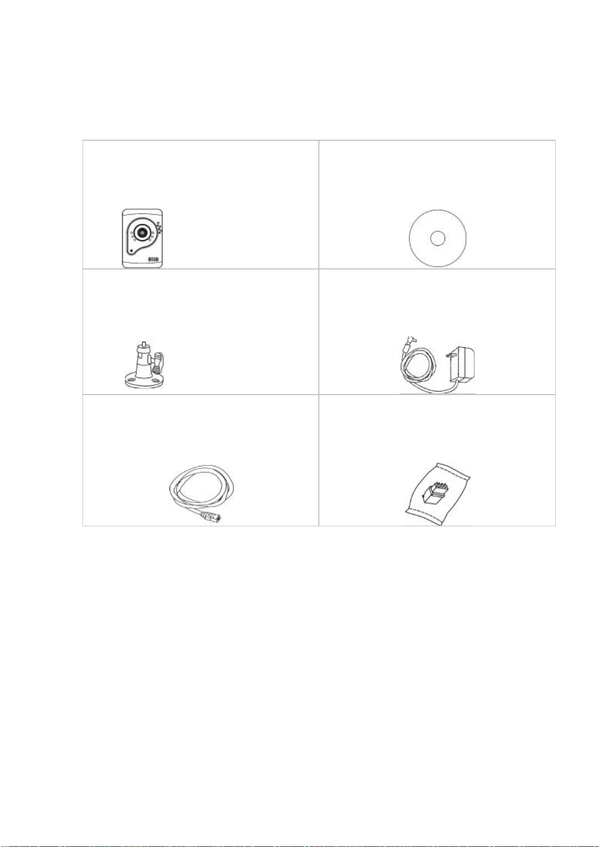
a. Network Camera
b. Product CD
c. Camera Stand
d. Power Adapter(Optional)
e. RJ-45 cable
f.
Terminal I/O Connector Block
Chapter 1- Package Contents
Please check to make sure that the product package contains all the accessories listed below.
-2-
Pin
Function
1
Ground
2
Digital Input
3
Digital Output
4
Power 5V
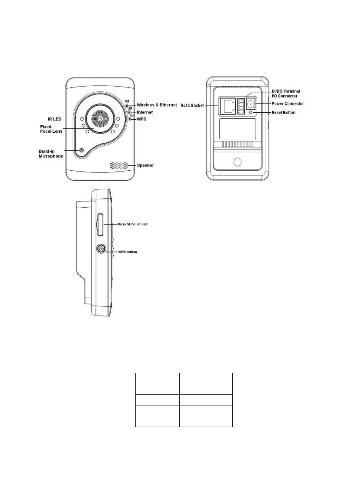
Chapter 2 -
C3xx3-W series
Device Appearance Description
Extension I/O Terminal Block (
C3xx3-W
)
The Network Camera provides an extension I/O terminal block which is used to connect the
camera with external input/output devices. The pin definitions are listed as below.
-3-
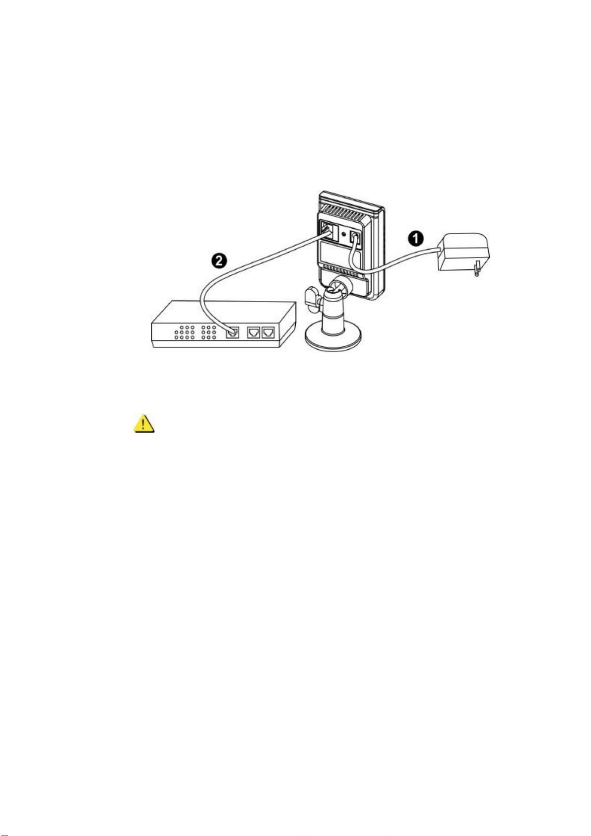
Chapter 3 - Camera Connection
Basic Connection
Basic Connection
1) Connect the supplied power cable from the camera to the power outlet.
2) Connect the camera to a switch via Ethernet cable.
1) Connect the camera to a switch using a standard Ethernet cable.
2) Connect the power adapter from the camera to a power outlet.
NOTE - DC12V 1A power adapter is required.
-4-

Chapter 6 - System Requirements
Operatin g
Microsoft Windows XP Home Edition SP2
Microsoft Windows XP Professional SP2
Com put er :
IBM PC/AT Compatible
CP U:
Pentium 3GHz or faster
Mem or y:
1024 MB or more
Monitor :
1024 x 768 pixels or more, 24-bit True color or better
Ne tw or k I nt er f ace :
System:
10/100Mbps Network interface card must be installed
Web
Browser:
Microsoft Internet Explorer 6.0 SP2 or higher
Adobe Re ad er :
Adobe Reader 8.0 or higher
Audi o:
The audio function will not work if a sound card is not installed in the PC. Audio
may be interrupted depending on network traffic.
-5-

Chapter 7 - Software Installation
In this manual, "User" refers to whoever has access to the Network Camera, and
"Administrator" refers to the person who can configure the camera and grant user access to
the camera.
After checking the hardware connection, run the Installation Wizard program included on the
product’s
CDROM to automatically search the intranet for the camera. There may be many
cameras on the local network. Differentiate the cameras using the serial number which is
printed on the labels on the carton and on the bottom of the camera.
1. Insert the Installation CD into the CD-ROM driver. Run the Auto-Run Tool directly
from the CD-ROM to start the installation. When installing the Network Camera Toolkit
for the first time, select a desired language for the interface. The available languages
are listed in the scroll box. Click <
Install IP Utility
> or <
Install PC-NVR
> to install. If
installing the PC-NVR program, please refer to the PC-NVR user manual. If installing
the IP Utility, follow the steps to install the IP Utility wizard on the desired computer.
-6-

2. In the Install Shield Wizard dialog box, click <Next> to continue.
3. Click <
Change
> to change the folder where installation and program files will be stored.
Click <Next> to continue.
-7-

i. Select to create shortcuts. Click <Next> to continue.
-8-

5. Click to launch the application, and click <
-9-
Finish
> to complete the installation.

IP Utility
To launch the IP Utility, an IP Utility icon was installed on the desktop. Double click on the icon
to open. The program can also be found in C:\Program Files\NetworkCamera\IP Utility unless
the program was saved to a preferred directory.
1. Click <
Start
> to continue. The program will automatically search for the camera
on the intranet.
- 10 -

2. There may be many cameras on the local network. Differentiate the cameras by
using their UPnP name. Double click on the camera from the survey list to
connect.
- 11 -

Authentication
To access the camera’s live view, open a web browser and enter the IP address of the camera.
A dialog window will pop requesting a username and password. The default username and
password for the Administrator are assigned as “
admin/admin
”. For non
administratoraccounts, users can choose to remember the password for future convenience.
However, It is not recommended that this feature be used when viewing the camera from a
public computer.
- 12 -

Installing the Plug-In
For initial access to the camera in Windows, the web browser may ask the administrator
for permission to install a new plug-in for Internet Explorer. Permission request depends
on the Internet security settings of the user’s PC or notebook. If the highest security level
is set, the computer may prohibit any attempt to install or run the program. This plug-in
has been certified and is used to display the video in the browser. Click on
to proceed. If the web browser does not allow the administrator to continue the installation,
check the Internet security options and lower the security levels or contact the network
supervisor or IT for help.
a.
NOTE
– After upgrading firmware of the camera, if
an error occurred or the plug-in fails to install. Please
refer to the following steps:Remove the
“
NetworkCamera Media Control Embedded”
via the
path “Control Table”->”Add/Remove program”.
b. Restart the computer.
c. Connect to the camera
d. Install the permission again.
-13-

Live View
Live View is the default page that opens when accessing the camera. Live video is
displayed directly in the window browser.
Stream1/Stream2 Channels
The network camera offers simultaneous dual stream for optimized quality and bandwidth.
Go to Configuration
Camera/Video/Audio
→
Video to configure the codec compression
→
and video resolution or refer to the Video configuration page.
HTTP/TCP/UDP protocol
HTTP
–
This unicast method can be used to traverse firewalls. Firewalls are commonly
configured to allow the HTTP protocol, thus allowing RTP to be tunneled.
TCP - This protocol guarantees the complete delivery of streaming data and provides
better video quality. The downside of using this protocol is that the quality of its real-time
effect is less than that of the UDP protocol.
UDP
- This protocol allows for more real-time audio and video streams. However, network
packets may be lost due to network traffic and images may be broken. Activate UDP
-14-

connection time - sensitive responses are more important than video quality.
(*) LED Control
– Use the drop-down menu to adjust the brightness of the camera’s LED.
-15-

Federal Communication Commission Interference Statement
This equipment has been tested and found to comply with the limits for a Class B digital device, pursuant to
Part 15 of the FCC Rules. These limits are designed to provide reasonable protection against harmful
interference in a residential installation. This equipment generates, uses and can radiate radio frequency
energy and, if not installed and used in accordance with the instructions, may cause harmful interference to
radio communications. However, there is no guarantee that interference will not occur in a particular
installation. If this equipment does cause harmful interference to radio or television reception, which can be
determined by turning the equipment off and on, the user is encouraged to try to correct the interference by
one of the following measures:
- Reorient or relocate the receiving antenna.
- Increase the separation between the equipment and receiver.
- Connect the equipment into an outlet on a circuit different from that to which the receiver is connected.
- Consult the dealer or an experienced radio/TV technician for help.
FCC Caution: Any changes or modifications not expressly approved by the party responsible for compliance
could void the user's authority to operate this equipment.
This device complies with Part 15 of the FCC Rules. Operation is subject to the following two conditions: (1)
This device may not cause harmful interference, and (2) this device must accept any interference received,
including interference that may cause undesired operation.
IMPORTANT NOTE:
Radiation Exposure Statement:
This equipment complies with FCC radiation exposure limits set forth for an uncontrolled
environment. This equipment should be installed and operated with minimum distance 20cm
between the radiator & your body.
This transmitter must not be co-located or operating in conjunction with any other antenna or transmitter.
Country Code selection feature to be disabled for products marketed to the US/CANADA
 Loading...