

Brickcom GOB-300Np-Star-KIT, OB-200Np-KIT, OB-200Np-V6-KIT, OB-300Np-Star-KIT, OB-500Ap-KIT User Manual
...
Hardware User’s Manual
Megapixel Day & Night
Outdoor Bullet Network Camera
Quality Service Group
Professional Outdoor Bullet Series

Product name:
Network Camera (Outdoor Bullet series)
Release Date:
2015/09
Manual Revision:
V4.0
Web site:
www.brickcom.com
Email:
support@brickcom.com
info@brickcom.com
© 2015 Brickcom Corporation. All Rights Reserved
Review History:
1. Separate User Manual into HW and SW.
2. Merge OB-100A V2 series /OB-130N-series into this User Manual.
3. Add OB-500A Series /OB-300N Series into the User Manual.
4. Clarify the OB series Reset button and WPS button.
5. HW add one function for TV out Connector.
6. Modify I/O Terminal Block definition.
7. Add OB-200Np-LR Series into the User Manual
8. Update OB-P series V6 version
9. Add WOB Series and GOB Series into the User Manual
1

Table of Contents
Before You Use This Product ....................................................................................... 3
Regulatory Information ................................................................................................. 4
Chapter 1 - Package Contents ...................................................................................... 5
Chapter 2 - Outdoor Bullet Network Camera Overview .............................................. 7
Chapter 3 - Device Appearance Description ............................................................... 8
Chapter 4 - Installation ................................................................................................ 14
4.1 Hardware Installation ....................................................................................... 14
4.2 Camera Connection ......................................................................................... 19
4.3 System Requirements ..................................................................................... 21
4.4 Software Installation ........................................................................................ 22
4.4.1 EasyConfig ............................................................................................ 30
2

Before You Use This Product
In many countries, there are laws prohibiting or restricting the use of surveillance
devices. This Network Camera is a high-performance, web-ready camera which can be
part of a flexible surveillance system. It is the user’s responsibility to ensure that the
operation of this camera is legal before installing this unit for its intended use.
Upon opening the product’s package, verify that all the accessories listed on the
“Package Contents” are included. Before installing the Network Camera, read the
warnings in the “Quick Installation Guide” to avoid misuse. When installing the Network
Camera, carefully read and follow the instructions in the “Installation” chapters to avoid
damages due to faulty assembly or installation.
3

Regulatory Information
Federal Communication Commission Interference Statement
This equipment has been tested and found to comply with the limits for a Class B digital
device, pursuant to Part 15 of the FCC Rules. These limits are designed to provide
reasonable protection against harmful interference in a residential installation. This
equipment generates uses and can radiate radio frequency energy and, if not installed
and used in accordance with the instructions, may cause harmful interference to radio
communications. However, there is no guarantee that interference will not occur in a
particular installation. If this equipment does cause harmful interference to radio or
television reception, which can be determined by turning the equipment off and on, the
user is encouraged to try to correct the interference by one of the following measures:
- Reorient or relocate the receiving antenna.
- Increase the separation between the equipment and receiver.
- Connect the equipment into an outlet on a circuit different from that to which the
receiver is connected.
- Consult the dealer or an experienced radio/TV technician for help.
FCC Caution: Any changes or modifications not expressly approved by the party
responsible for compliance could void the user's authority to operate this equipment.
This device complies with Part 15 of the FCC Rules. Operation is subject to the following
two conditions: (1) This device may not cause harmful interference, and (2) this device
must accept any interference received, including interference that may cause undesired
operation.
IMPORTANT NOTE:
FCC Radiation Exposure Statement:
This equipment complies with FCC radiation exposure limits set forth for an
uncontrolled environment. This equipment should be installed and operated with
minimum distance 20cm between the radiator & your body.
This transmitter must not be co-located or operating in conjunction with any other
antenna or transmitter.
The availability of some specific channels and/or operational frequency bands are
country dependent and are firmware programmed at the factory to match the
intended destination. The firmware setting is not accessible by the end user.
4
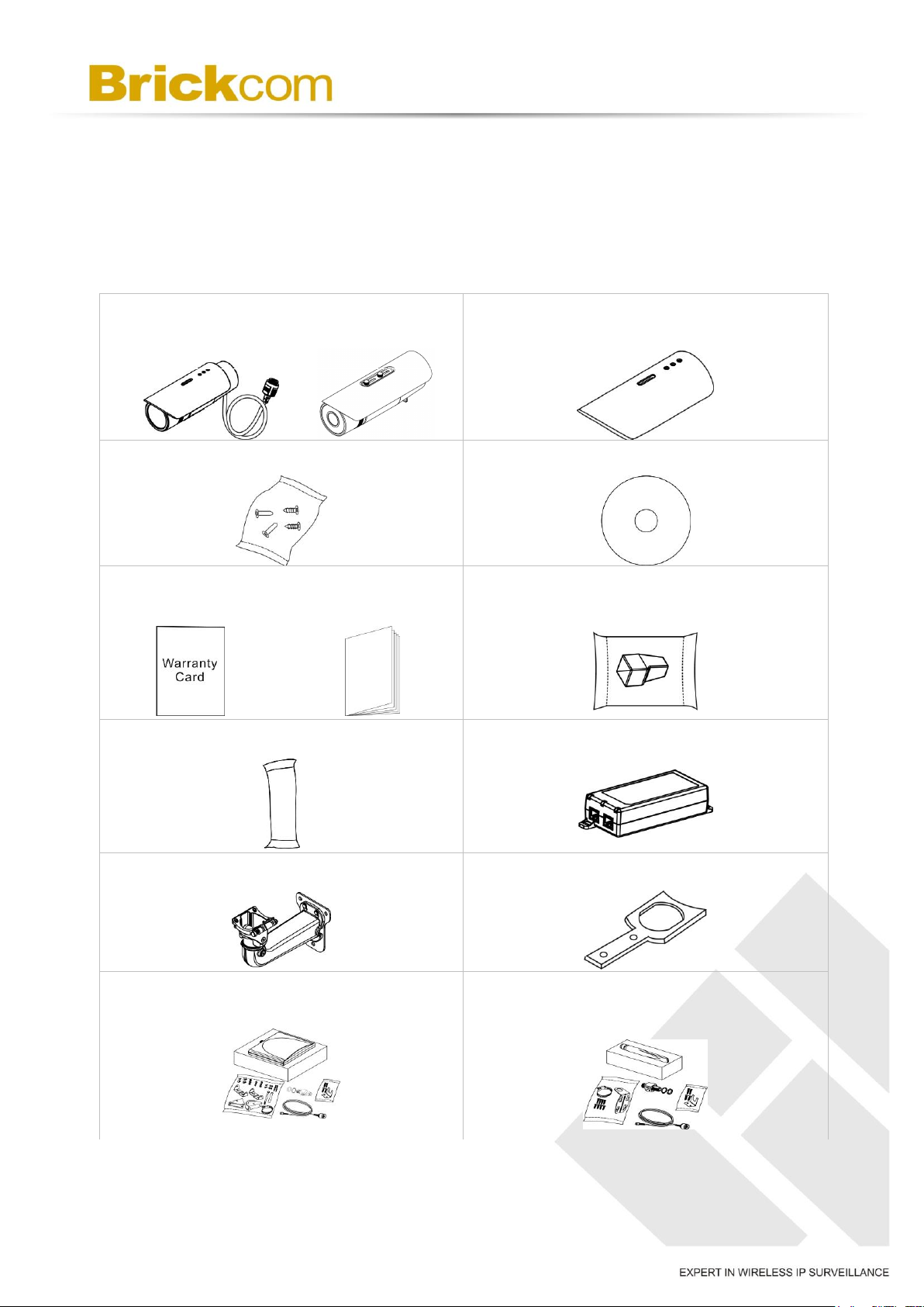
a. Network Camera
b. Shielding Cover
c. Screw bag
d. Product CD
e. Warranty Card / Easy Installation
Guide
f. Water Proof Connectors
g. Dry Bag
h. High Power POE (Optional)
i. Bracket (Optional)
j. Bracket Assembly Plate (Optional)
k. Wi-Fi Dual Band Antenna package
(Optional)
l. 3G Antenna package (Optional)
OB-p Series
OB-p-LR Series
Chapter 1 - Package Contents
Please check to make sure the product package contains all the accessories listed
below.
A. Camera Package Contents
5
m. Power adapter (Non LR-Series)
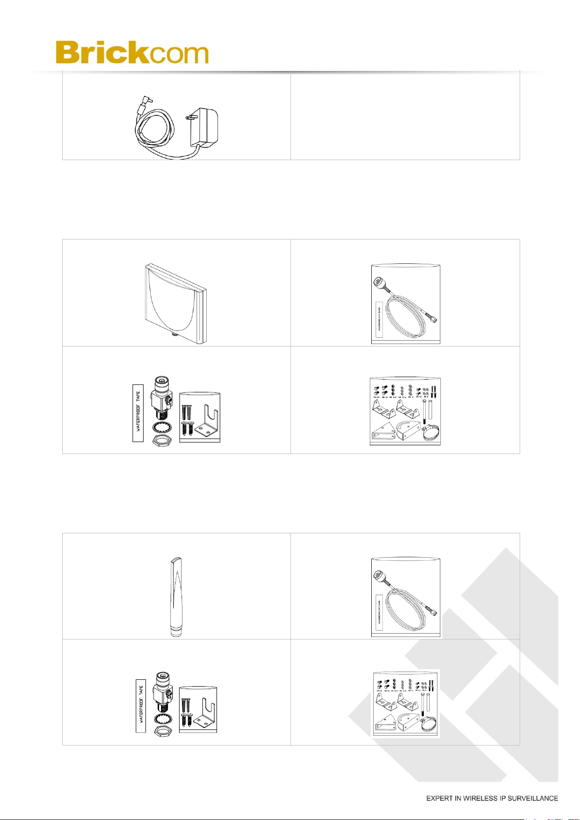
a. Wi-Fi Dual Band Antenna
b. Extension Cable
c. Surge Arrestor Kit
d. Mount Kit
a. 3G / 4G LTE Antenna
b. Extension Cable
c. Surge Arrestor Kit
d. Mount Kit
B. Wi-Fi Antenna Package contents (Optional for WOB-P Series)
Refer to the installation guide included in the package when installing the
Wi-Fi antenna
C. 3G / 4G LTE Antenna Package contents (Optional for GOB-P series)
Refer to the installation guide included in the package when installing the
3G antenna
6
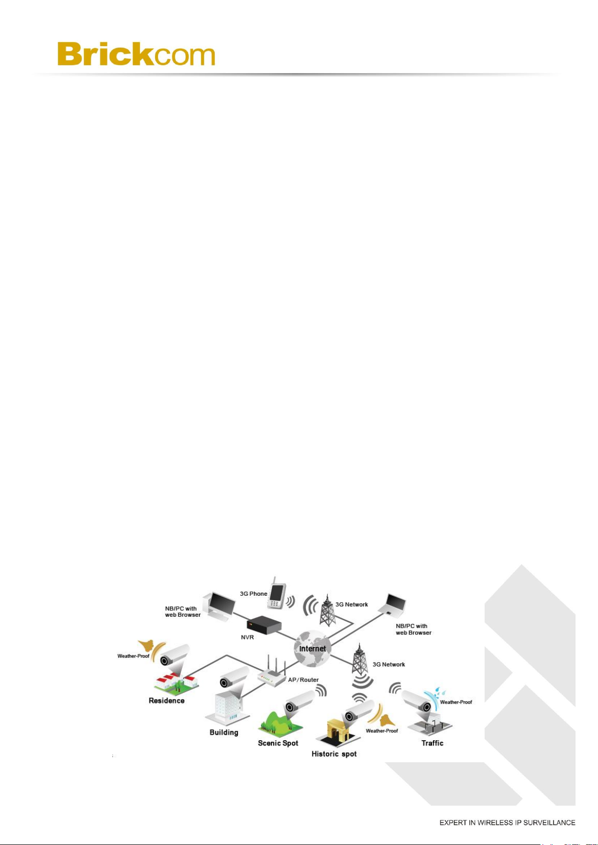
Chapter 2 - Outdoor Bullet Network Camera
Overview
The Brickcom Outdoor Bullet SERIES is an outdoor bullet network camera. It adopts a
megapixel sensor which allows the camera to deliver extremely clear and detailed
images that CCTV cameras cannot offer. To optimize use of the megapixel resolution,
the Outdoor Bullet SERIES uses efficient H.264/ MJPEG/ MPEG-4 codec compression
to deliver dual configurable video streams simultaneously at up to 30 fps. These
features make this series the perfect outdoor camera for neighborhood, school campus,
and parking lot surveillance.
The Outdoor Bullet SERIES has many user friendly features, such as the Smart Focus
capability which allows users to configure settings for excellent image quality without
difficult procedures. Support for Power over Ethernet enables the camera to use the
same cable for power and data transmission, eliminating the need to install an external
power supply.
Installation for the WOB/GOB Series models is not restricted by location or landforms.
The cameras offer various wireless options that make connecting to networks easier by
adopting the technology of IEEE 802.11 a/b/g/n and 3G SIM module. The wireless
Bullet Cameras can be set within any wireless or 3G signal coverage areas. Users do
not have to worry about the data connection failing because each camera is equipped
with a SD/SDHC memory card slot for local storage.
With an IP67 certified outdoor enclosure, the Outdoor Bullet SERIES is not only weather
proof, but also dust and rust resistant. By utilizing a built-in industrial fan and heater, it
can perform well in extreme environments.
7
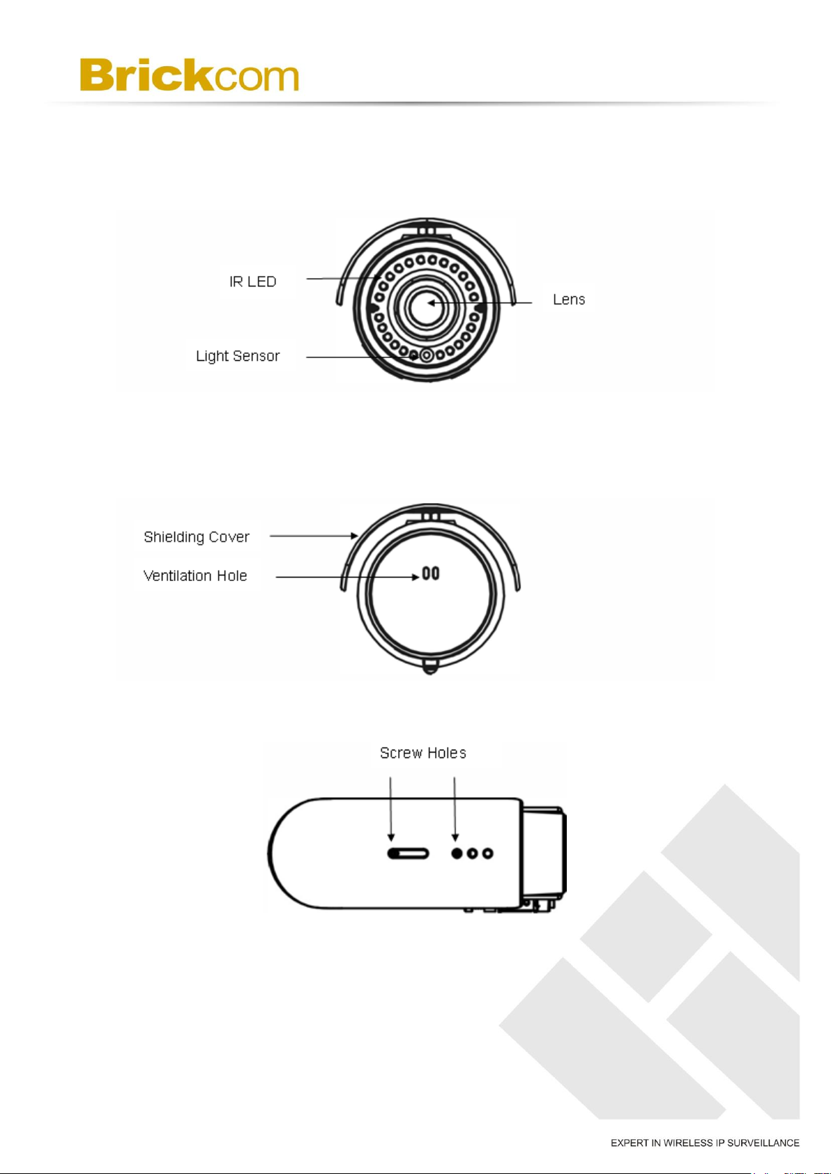
Chapter 3 - Device Appearance Description
< Front Panel >
< Rear Panel >
< Top >
< Bottom >
8
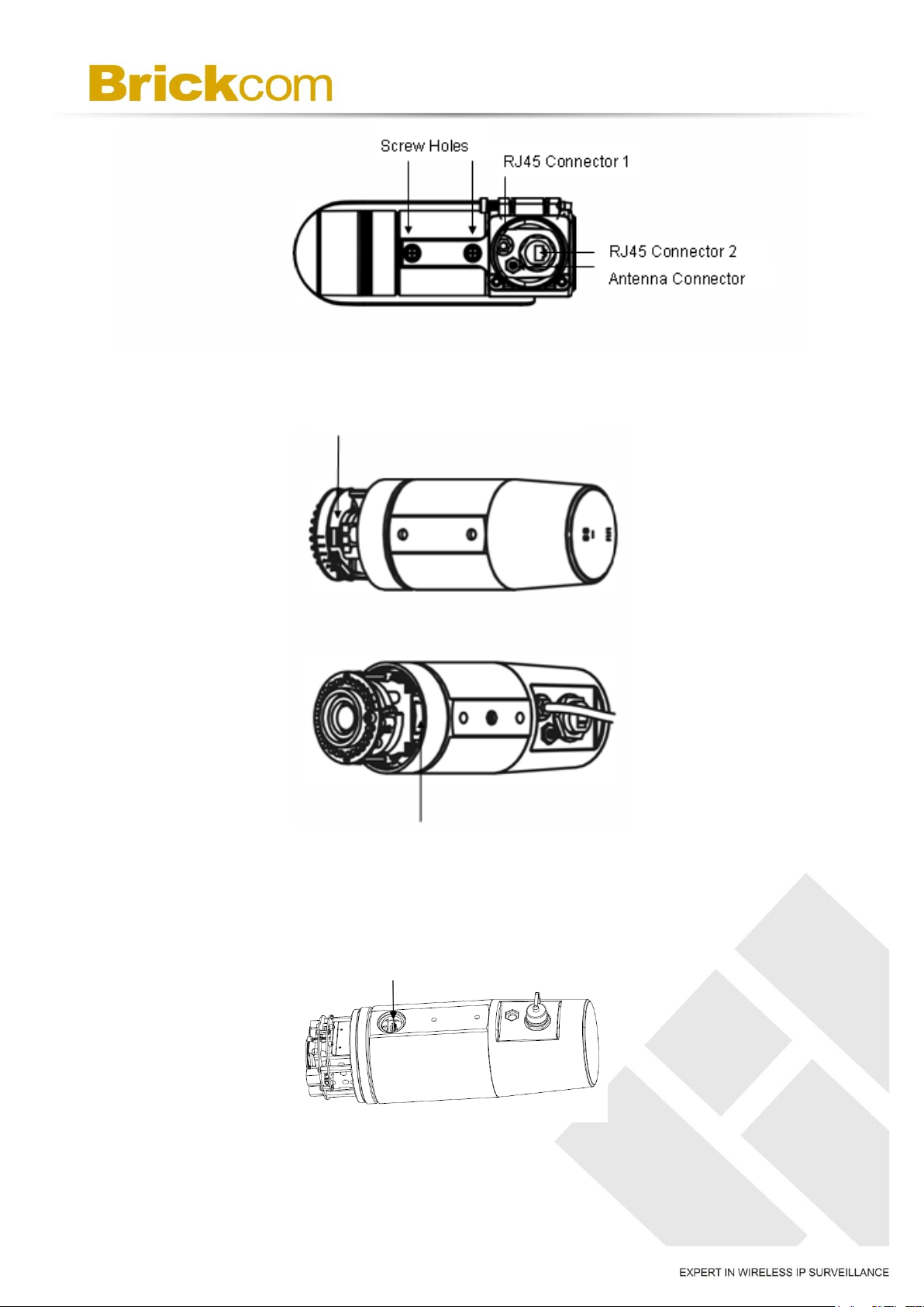
Micro-SD/SDHC Card Slot
3G SIM Card Slot
Micro-SD/SDHC/SDXC Card Slot
< Side >
**3G SIM Card Slot only apply for GOB & WOB series**
< OB-p-LR series >
9
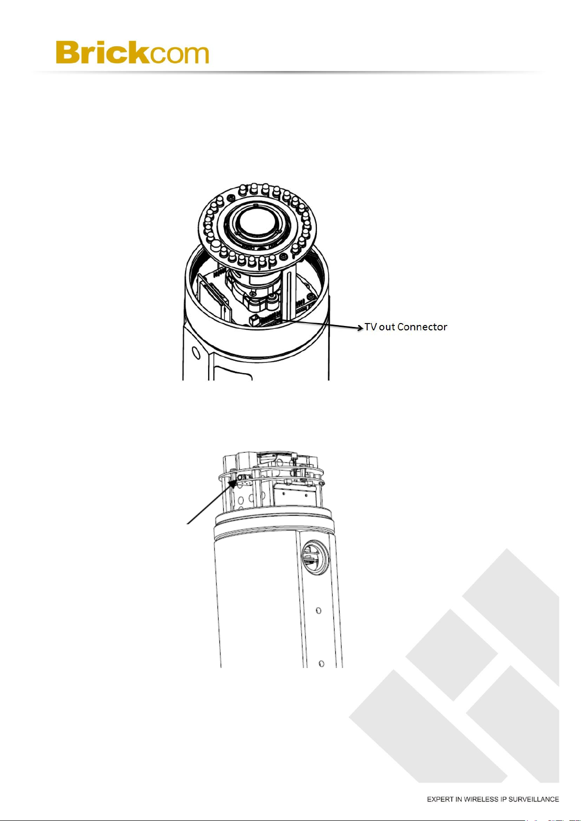
TV out Connector
<Inside> TV out Connector
***This function only apply below models.***
OB-502A Series/OB-500A Series and OB-302N Series/OB-300NSeries
< OB-p-LR series >
10
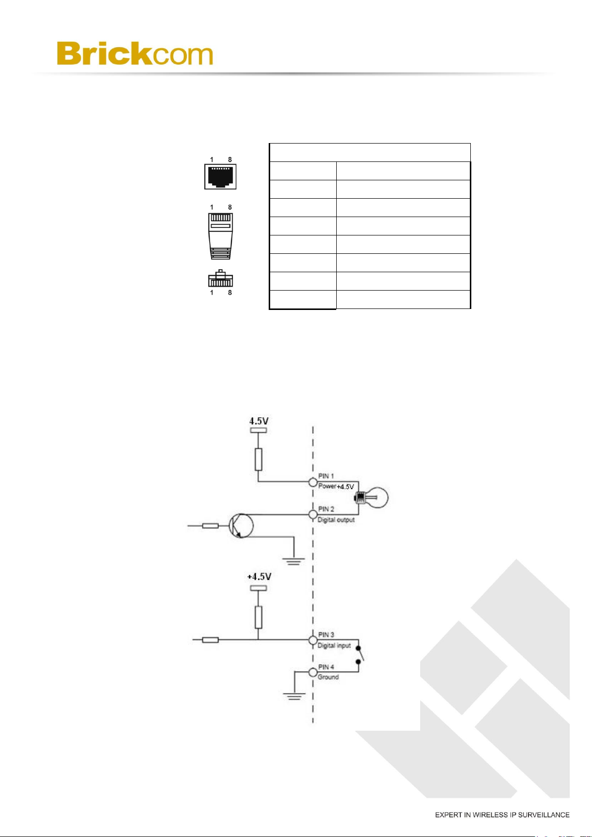
Pin No.
Pin 1
Power +4.5V / 12V*
Pin 2
Digital Output
Pin 3
Digital Input
Pin 4
Ground
Pin 5
RS-485-
Pin 6
RS-485+
Pin 7
Audio-in
Pin 8
Audio-out
/ +12V*
/ +12V*
/ + 12V*
< Extension I/O Terminal Block >
The Network Camera provides an extension I/O terminal block which is used to connect
the camera with external input/output devices. The pin definitions are listed as below.
* V5 & V6 Series Supported*V5&V6 (WDRPro & Star & StarPlus) Series Supported
DI/DO Diagram >
OB-100Ap Series and OB-130N Series
11
 Loading...