

Page 1
Megapixel Day & Night
Fixed Box Network Camera
FB-100A/FB-130A/FB-131A/FB-300A
Series
Quick Installation Guide
Quality Service Group
Page 2
Read Before You Use
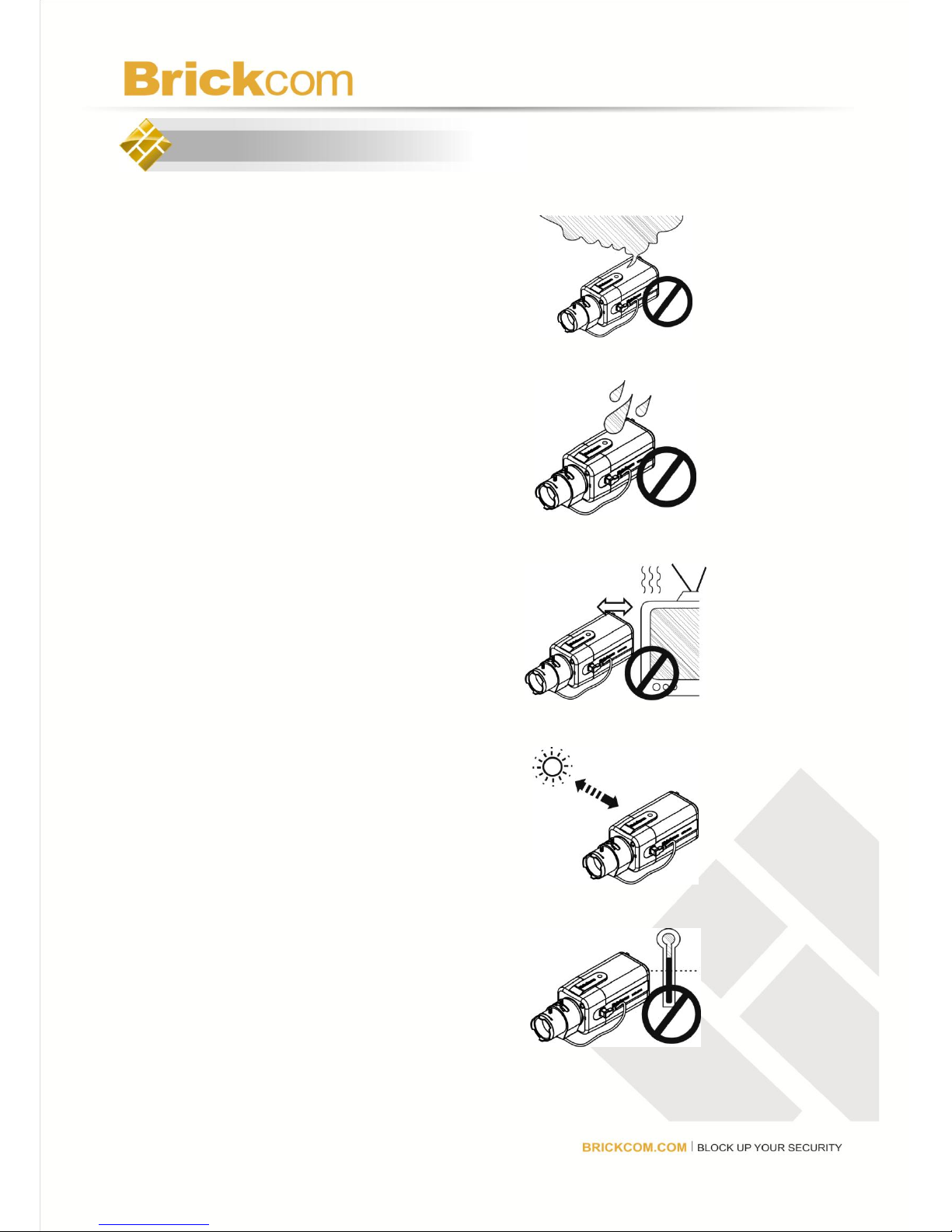
1. Power off the camera device
immediately if it starts smoking or
smells unusual.
2. Power off the camera device
immediately if the camera is
exposed to rain or liquid.
3. Do not set the camera device near
any heat sources. (Ex: television and
oven)
4. Keep the camera device away from
direct sunlight.
5. Do not set the camera device over
the specific operating temperature.
Page 3
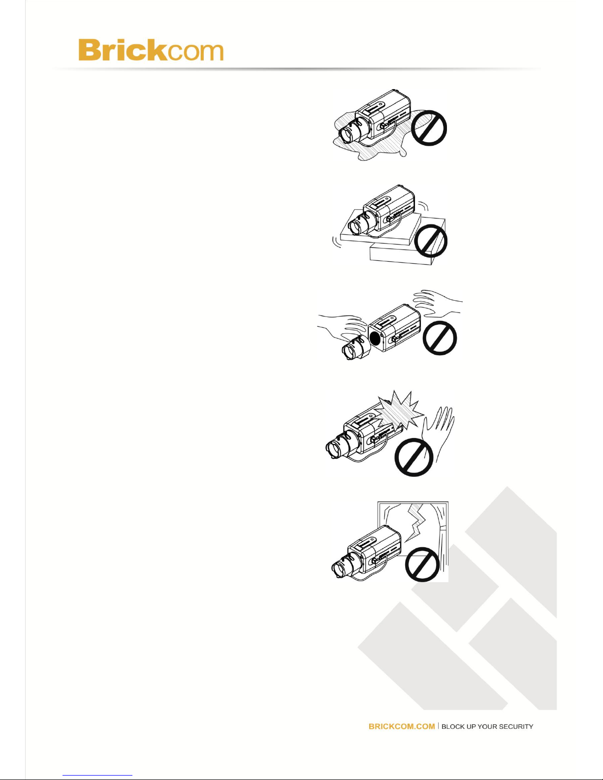
6. Do not set the camera device in any
wet and humid environments.
7. Do not set the camera device on
unsteady surfaces.
8. Do not attempt to dismantle the
camera device.
9. Do not drop or hit the camera device.
10. Do not use the camera device when
there is lightning.
Page 4
1. Check Package Contents
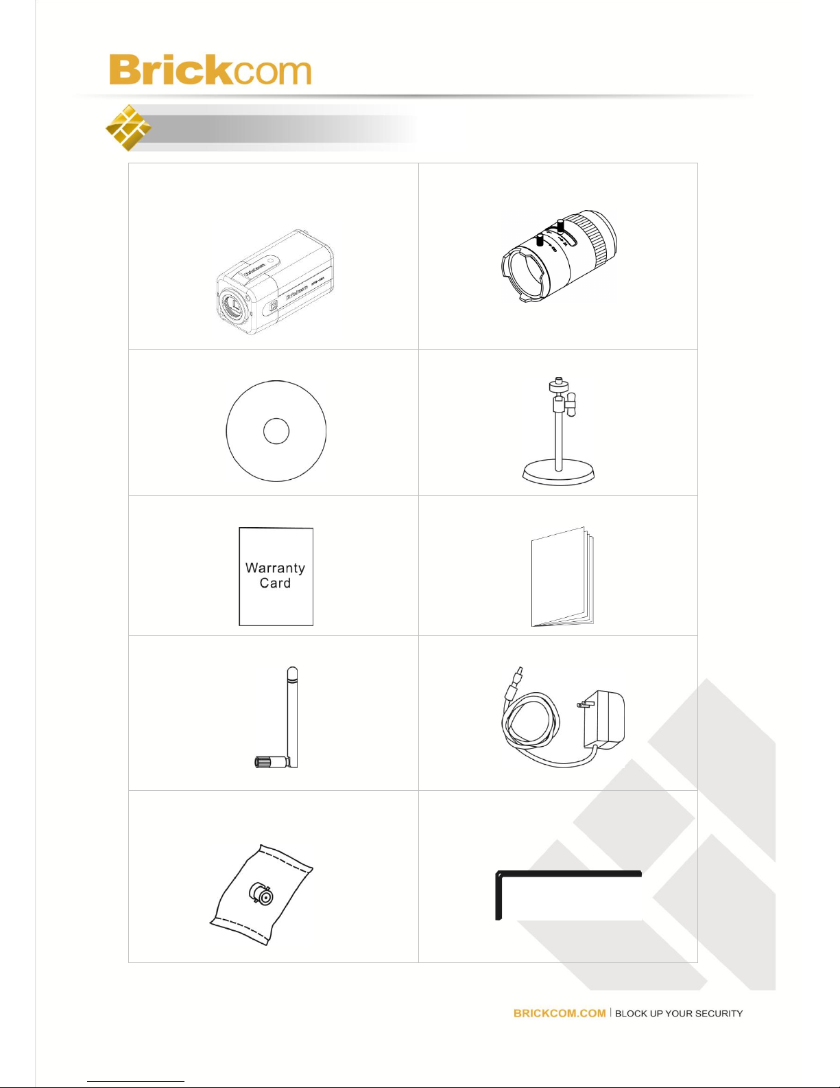
a. Network Camera
(FB-100A/FB-130A/FB-131A/FB-300A)
b. CS mount Lens (Optional)
c. Product CD
d. Camera Stand
e. Warranty Card
f. Easy Installation Guide
g. Detachable Antenna (Optional)
h. Power Adapter (Optional)
i. BNC Adapter (FB-130A only)
j. Allen Key
Page 5
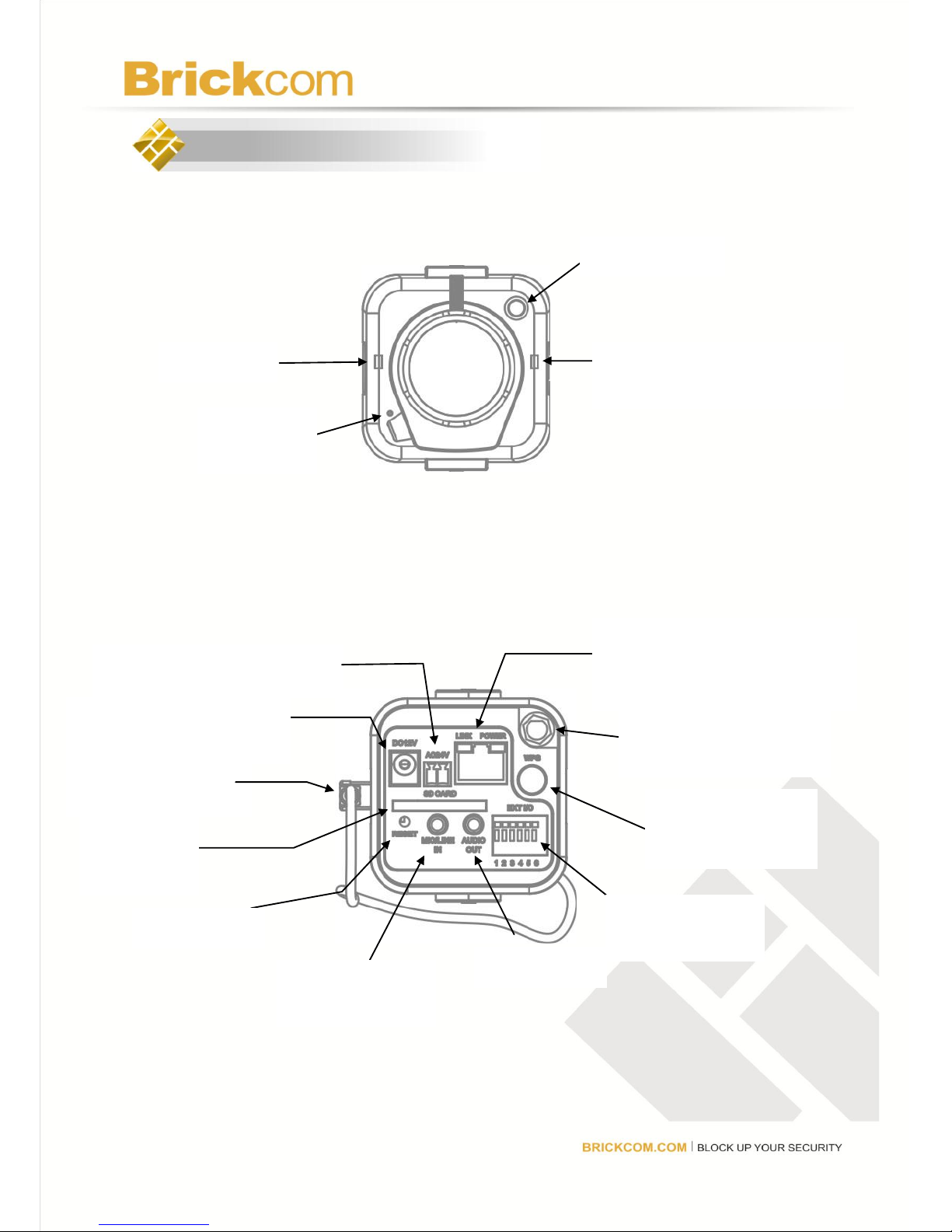
2. Device Description
<Front Panel>
<Rear Panel>
Light Sensor
WPS LED (*)
Status LED
Built-in
Microphone
WPS Button (*)
Ethernet RJ45 10/100 Socket
(Link/Power LED embedded)
Power Connector (AC24V in) (*)
Power Connector
(DC12V in)
SD/SDHC
Card Slot (*)
Reset Button
Microphone/Line
In
Audio Out
Detachable Antenna (*)
Auto Iris Connector (*)
Extension I/O
Terminal Block
Page 6
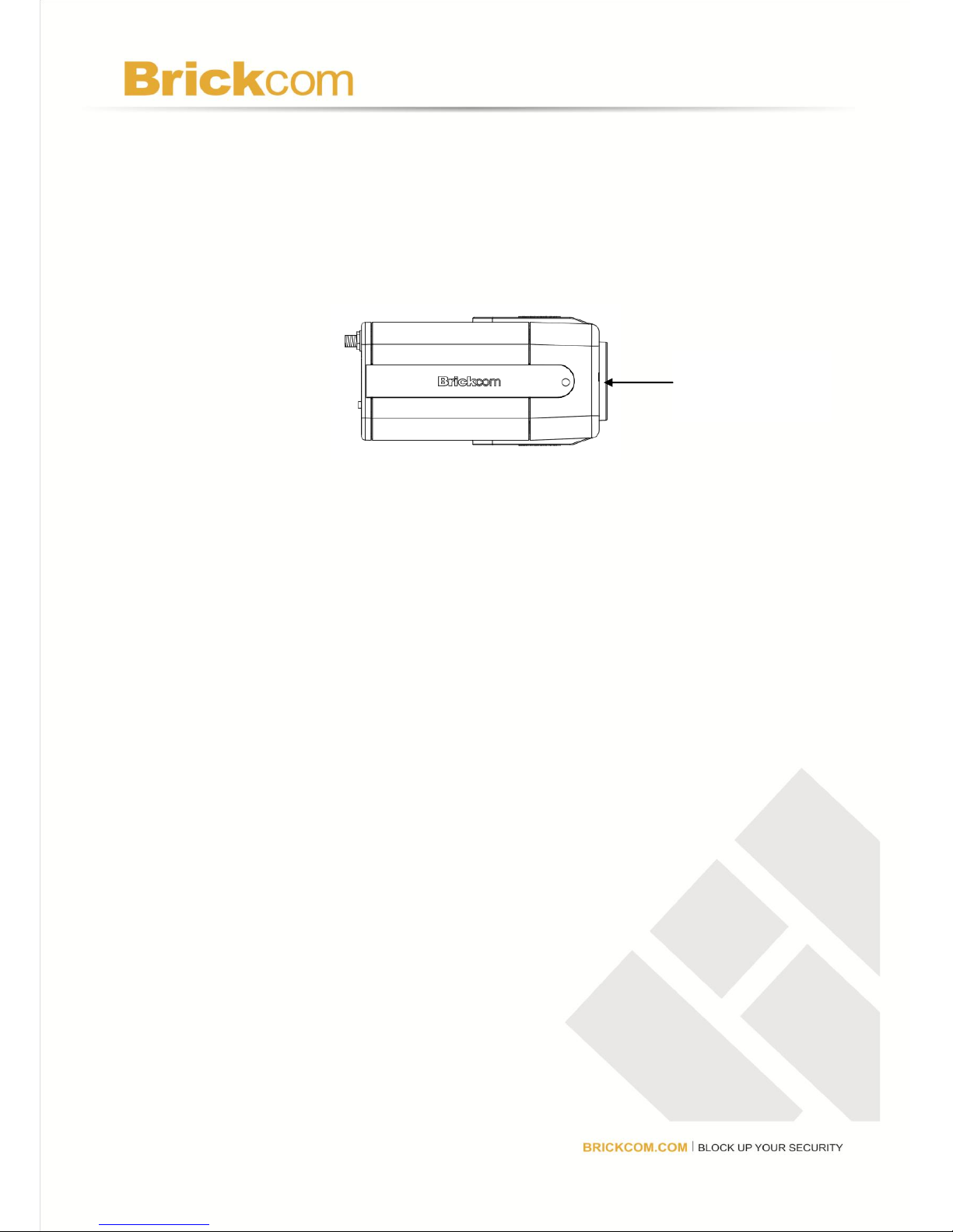
< Side View >
(*) These are optional features. Please refer to the Product List for the full list
of optional features that are available for this product.
Monitor Output
Connector
(FB-130A only)
Page 7
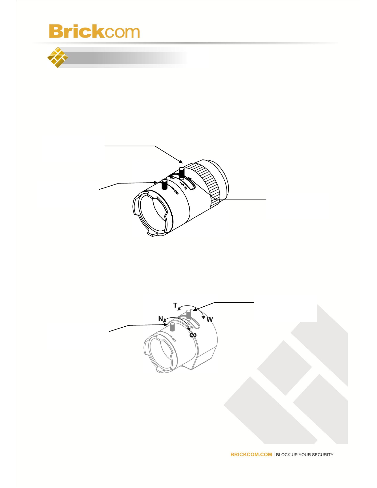
3. Optional for CS Mount Lens
<Optional Lens>
<Vari-focal Lens with Manual Iris> --- CS Mount
<Optional Lens>
<Vari-focal Lens with Auto Iris (DC Drive)> --- CS Mount
Zoom Controller (*)
Focus Controller
Zoom Controller
Focus Controller
Iris Controller (*)
Page 8
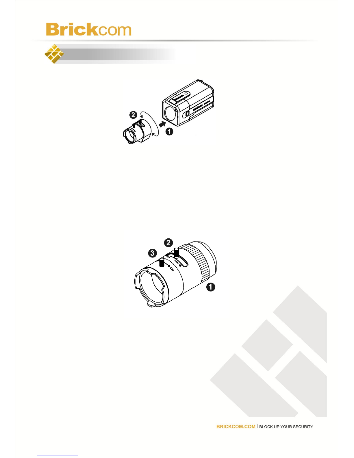
4. Connecting the CS-Mount Lens to the Camera
<Vari-focal Lens with Manual Iris> --- Optional Lens
1. Connect the CS-mount lens to the camera by turning it clockwise onto the
camera mount until it stops.
2. If necessary, adjust the iris controller, focus controller, and zoom controller to
get the best resolution.
To adjust the lens:
1. Adjust the iris ring controller to control the amount of light coming through
the lens. The more the iris is opened, the brighter the scene will be.
2. The zoom controller can be manually adjusted to control the zoom factor
on the camera. Users can create a tighter or wider view of the site being
recorded.
3. Adjust the focus controller to control the focus range of the lens.
Page 9

<Vari-focal Lens with Auto Iris> --- Optional Lens
1. Connect the CS-mount lens to the camera by turning it clockwise onto the
camera mount until it stops.
2. If necessary, adjust the iris controller, focus controller, and zoom controller
to get the best resolution.
3. Connect the lens cable plug (DC Iris control cable) to the camera side
connector.
To adjust the lens:
1. The zoom controller can be manually adjusted to control the zoom factor
on the camera. Users can create a tighter or wider view of the site being
recorded.
2. Adjust the focus controller to control the focus range of the lens.
Page 10
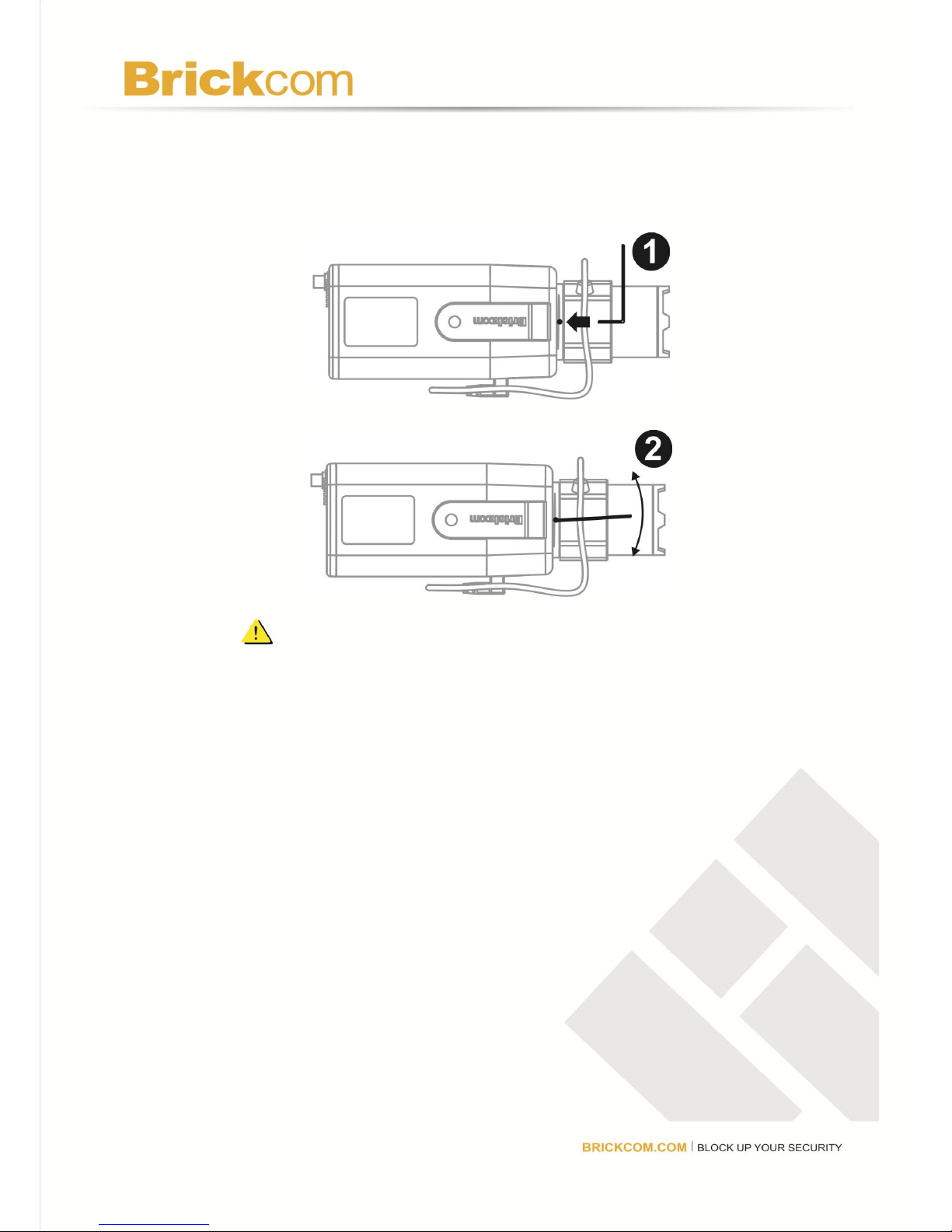
To adjust the CS-ring:
If the fixed box is still not focusing correctly on the target, use an Allen Key
to adjust the location of the CS-ring, then try focusing again.
NOTE - For further information of vari-focal lens with auto iris,
please refer to the supplied lens’ instruction manual.
Page 11
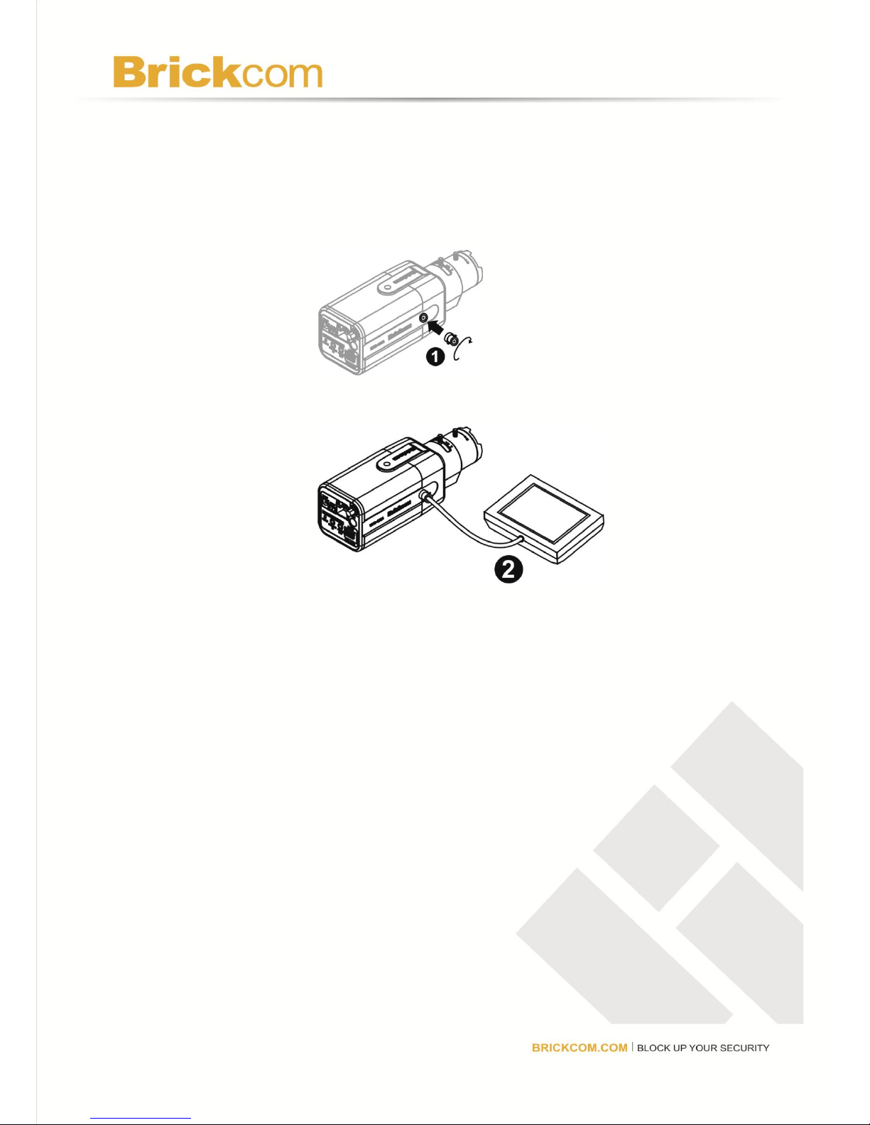
<Connect a Monitor to the Camera: (FB-130A only)>
Use a BNC adapter to view the camera’s video feed and manually adjust the lens
iris, focus, and zoom to get the desired image quality.
1. Connect the BNC adapter to the side of the camera.
2. Connect the monitor to the BNC adapter.
Page 12
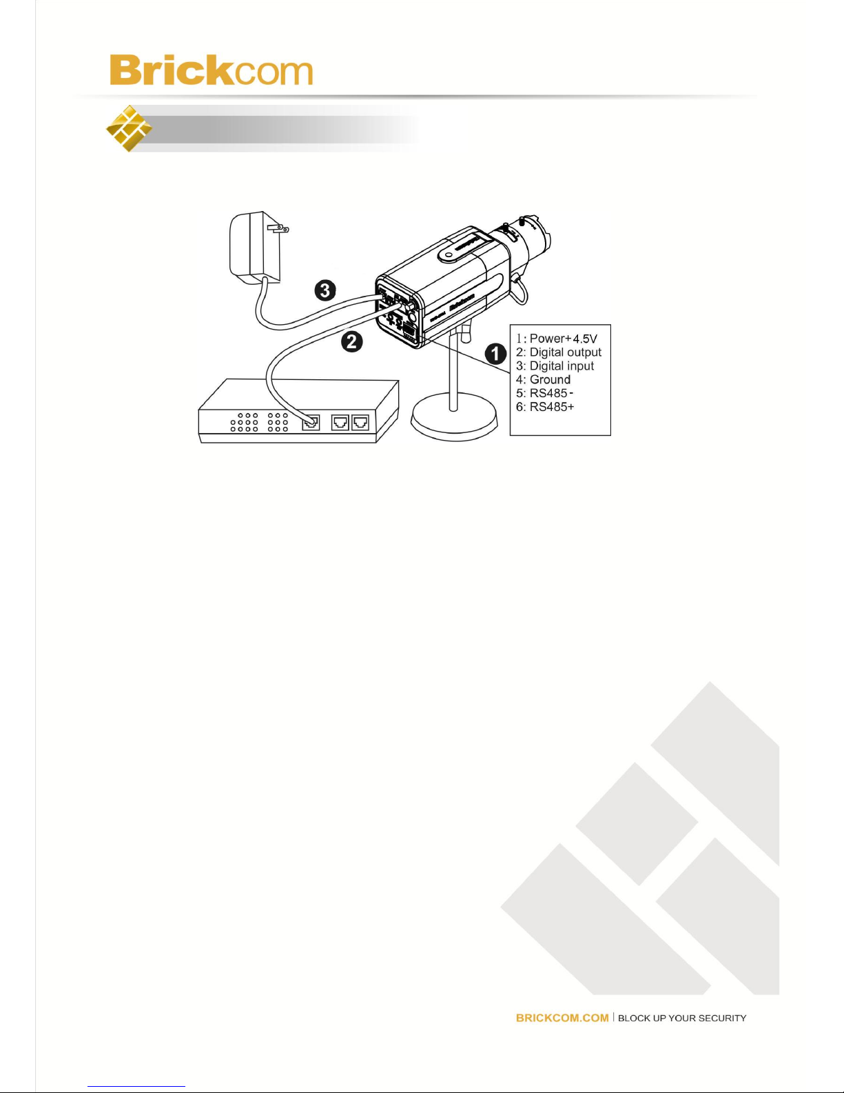
5. Camera Connection
Basic Connection (Without PoE)
1. To attach external devices, such as sensors and alarms, connect them to the
extension I/O terminal block.
2. Connect the camera to a switch using an Ethernet cable.
3. Connect the supplied power cable to the camera and plug it into a power
outlet.
Page 13
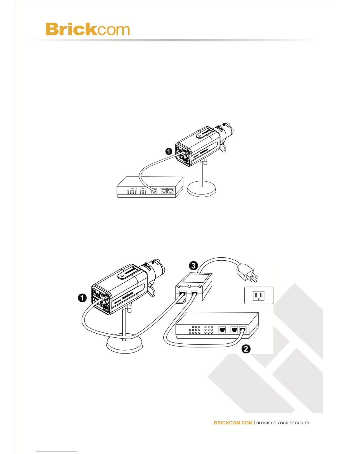
Power over Ethernet (PoE) Connection
The FB-100A is PoE compliant, so there are two options for connecting the
camera to a power and Ethernet source. The camera can either be connected to
a PoE-enabled switch or a non-PoE switch.
A. If using a PoE-enabled switch:
1. Use a single Ethernet cable to connect the camera to the PoE-enabled
switch.
B. If using a non-PoE switch:
1. Use a standard RJ-45 cable to connect the camera to a PoE Injector.
2. Use a standard RJ-45 cable to connect the PoE Injector to the non-PoE
switch.
3. Use a standard power cable to connect the PoE Injector to a power outlet.
Page 14
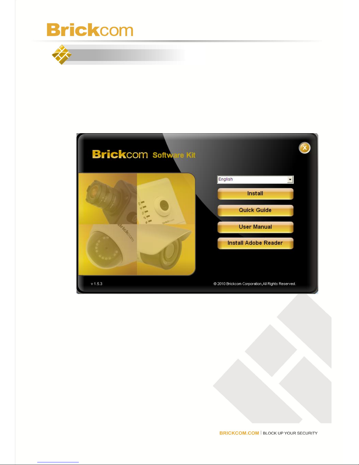
6. Setup the Network Camera
1. Insert the Installation CD into the CD-ROM driver. Run Auto-Run Tool
directly from the CD-ROM to start the installation. When installing the
Brickcom software kit for the first time, select a desired language for the
interface. The available languages are listed in the scroll box. Click
<Install> and follow the steps to install the EasyConfig wizard on the
desired computer.
Please follow the instruction of the InstallShield Wizard to finish the
Brickcom Software Kit installation.
Page 15
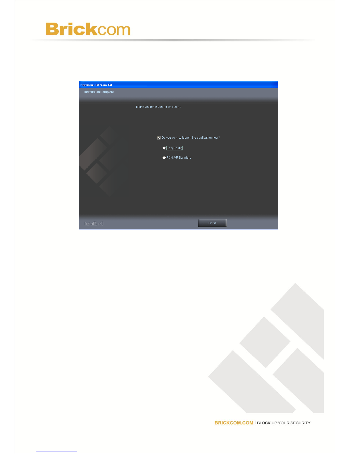
2. To launch EasyConfig or PC-NVR Standard, select the application and
click <Finish>. When launching the PC-NVR program, please refer to
the PC-NVR user manual.
Page 16
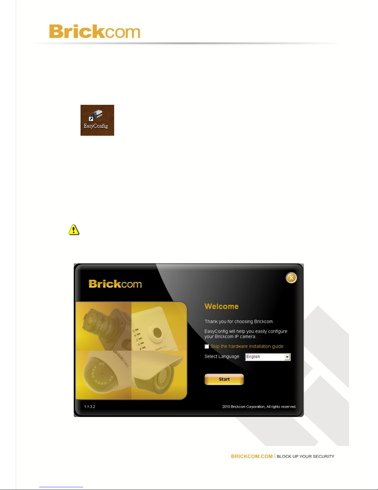
EasyConfig
To launch EasyConfig, select EasyConfig from the start menu. If Complete
Setup type was used in the software installation, an EasyConfig icon was
installed on the desktop. Double click to open the icon.
If Custom Setup type was used in the software installation and an EasyConfig
icon was not installed on the desktop, the program will be installed under
C:\Program Files\Brickcom\EasyConfig unless the program was saved to a
preferred directory.
1. Click <Start> to continue. The program will automatically search
for the camera in the intranet.
NOTE - Check “Skip the hardware installation guide” to skip checking the
hardware connection. To check the hardware installation settings, do not
check the option box.
Page 17
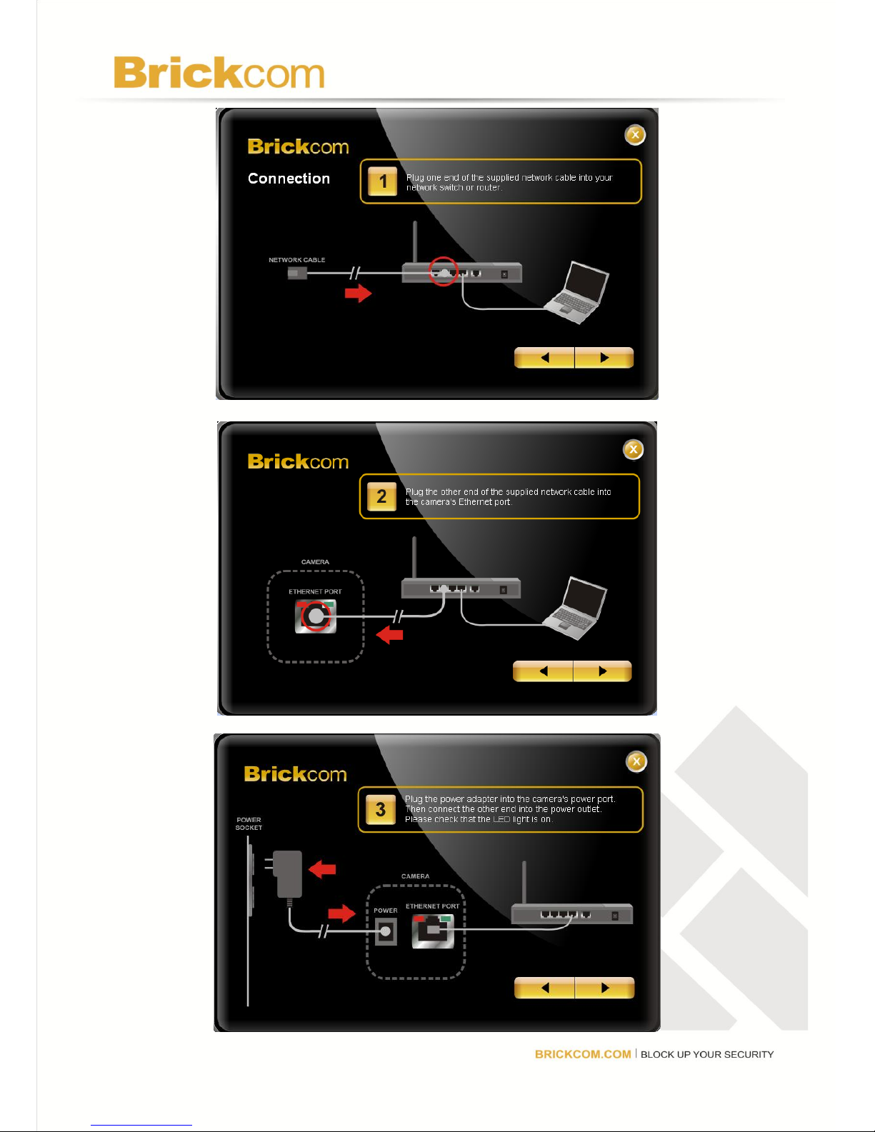
Page 18
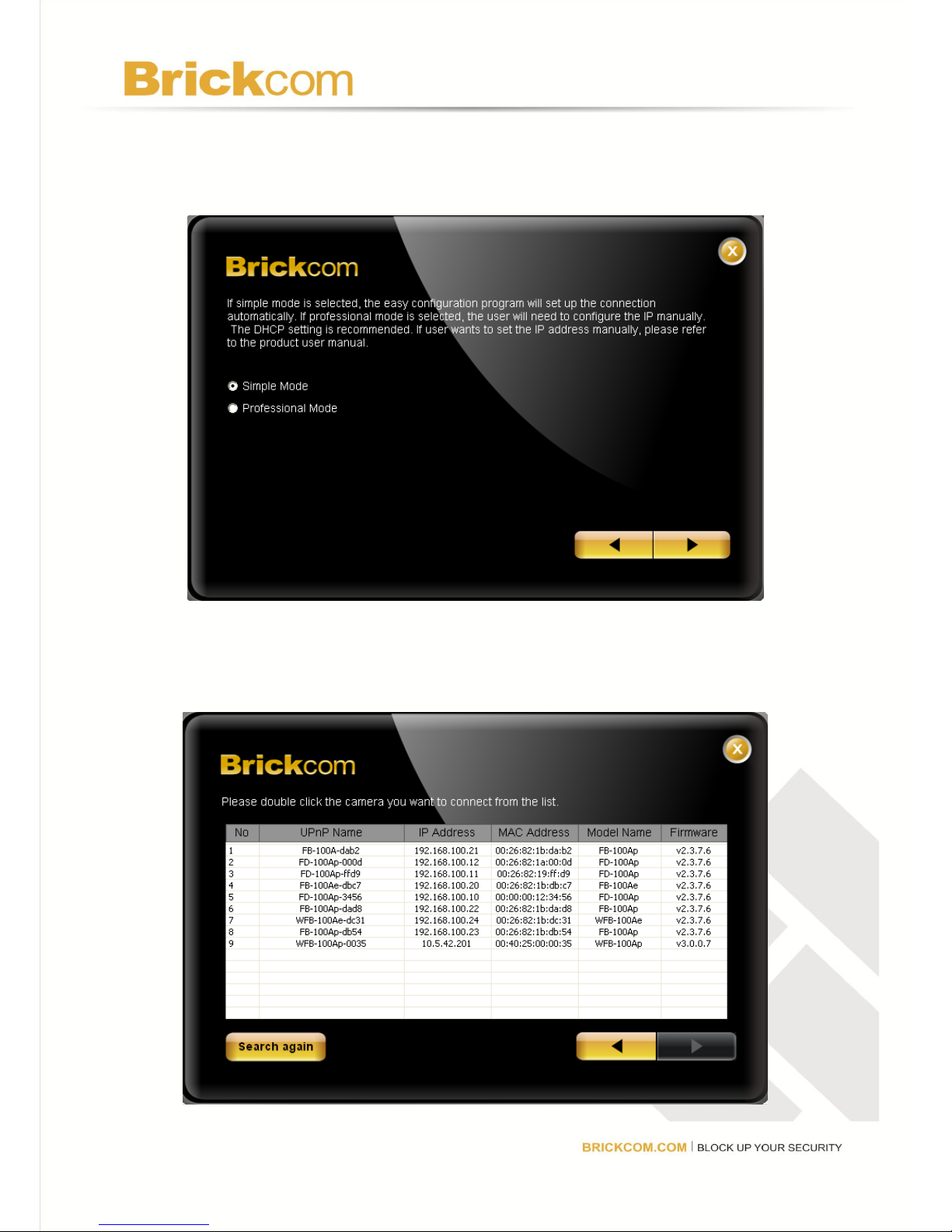
2. Select either “Simple Mode” or “Professional Mode” to obtain the
camera’s IP settings. If “Simple Mode” is selected, EasyConfig will
set up the connection automatically. If “Professional Mode” is
selected, the user will need to configure the IP settings manually.
3. There may be many cameras in the local network. Differentiate the
cameras using their UPnP name. Double click on the camera from
the survey list to connect.
Page 19
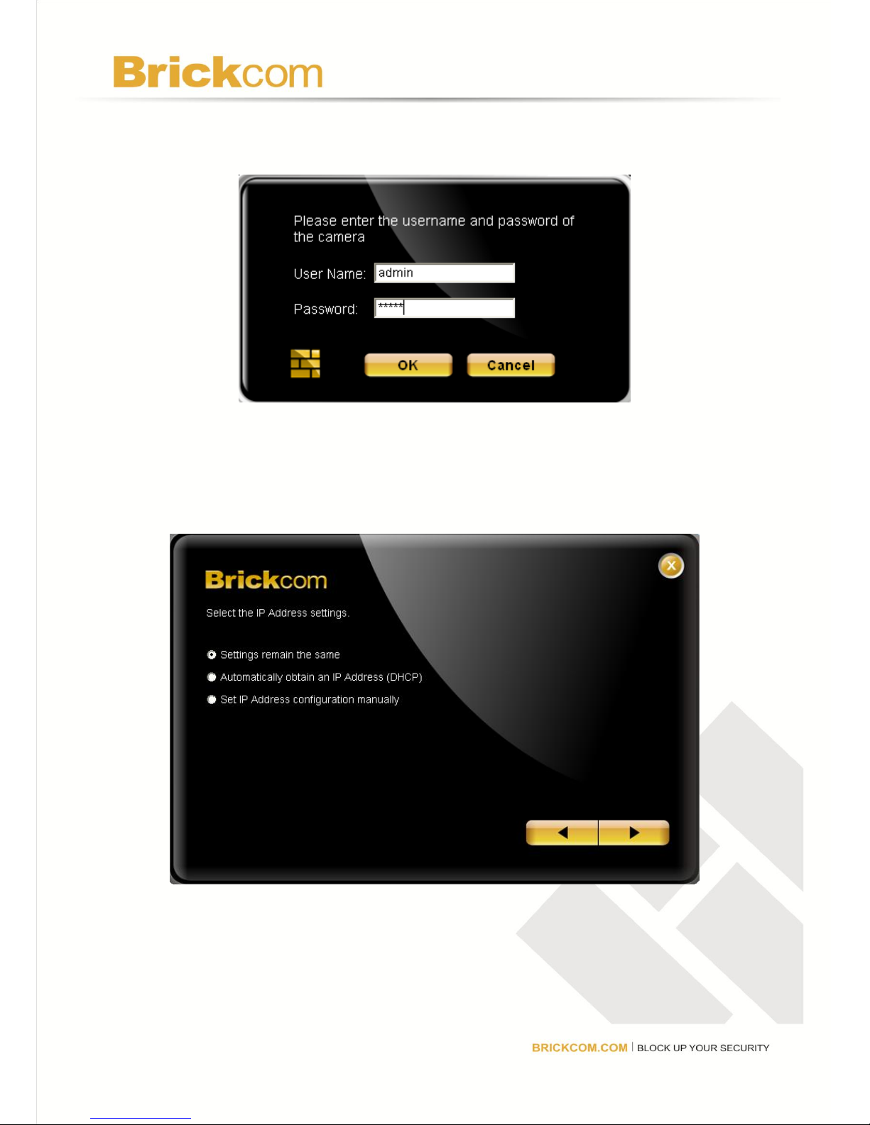
4. Enter the username and password of the camera. For first time
use, the default username and password are “admin/admin.”
5. For configuring the IP address settings, select either <Settings
remain the same>, <Automatically obtain an IP Address (DHCP)>
or <Set IP Address configuration manually>. The DHCP setting is
recommended.
Page 20
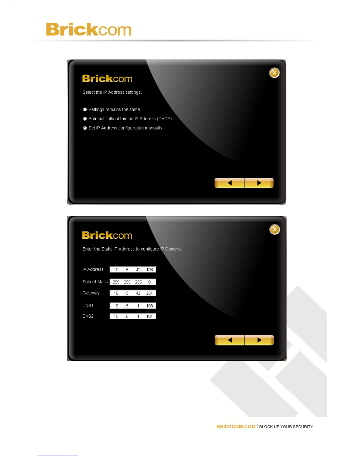
a. If <Set IP Address configuration manually> is selected, the
following pages will be displayed.
Page 21
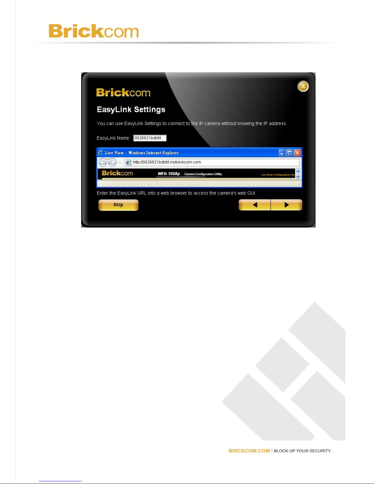
6. If the camera supports the EasyLinkTM function, the following
page will be displayed. Otherwise, this page will not be shown.
*If desired, click <Skip> to skip this setting.
EasyLinkTM is a unique Brickcom function which allows users to assign a unique
EasyLink name to their network camera’s IP address. There is no need to
configure the router to open up ports or remember hard-to-memorize IP
addresses. Users can log onto [uniqueEasyLinkname].mybrickcom.com to
view the camera’s web GUI and live view.
1. Enter a unique EasyLink name whose length must be between 5-32
characters.
2. When finished, click the arrow button to continue.
Page 22
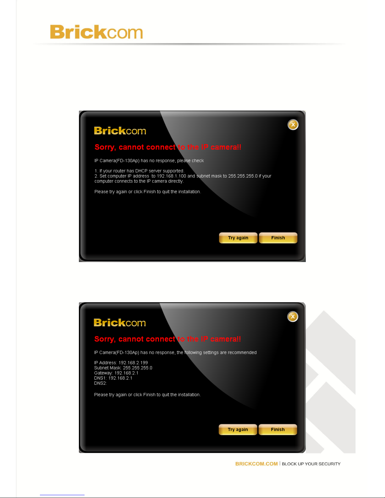
7. When the IP address settings have been configured, the screen will
either display a successful or failed connection message. If the
connection failed, either try again or quit the installation.
a. If “DHCP IP address settings” was selected, the failure page will
be displayed as below:
b. If “Static IP address settings” was selected, the failure page will
be displayed as below:
Page 23
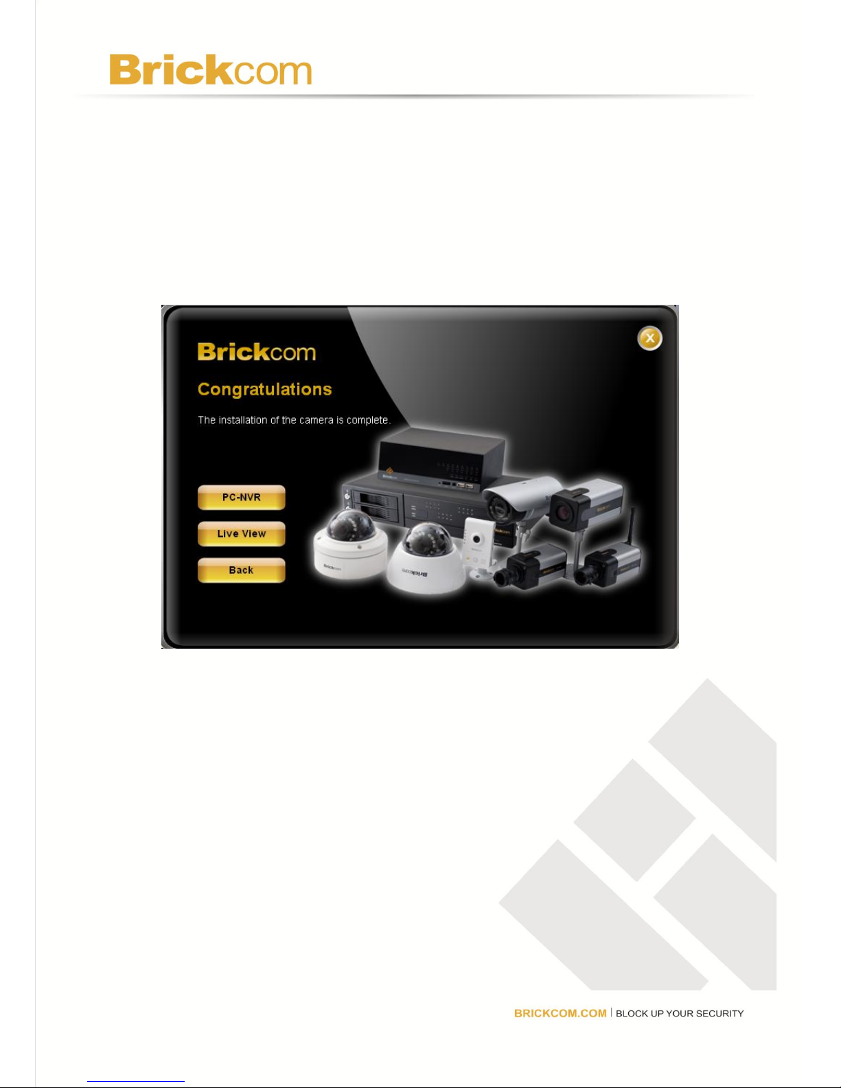
c. If the connection was successful, the user will see the message:
“Congratulations. The installation of the camera is complete.”
When this window is displayed, click <PC-NVR> to start the PC-NVR
program, <Live View> to view the live video from the connected IP
camera, or <X> in the top right corner of the screen to close the
installation window. To run the PC-NVR program, please refer to the
PC-NVR user manual for more information.
 Loading...