

Page 1
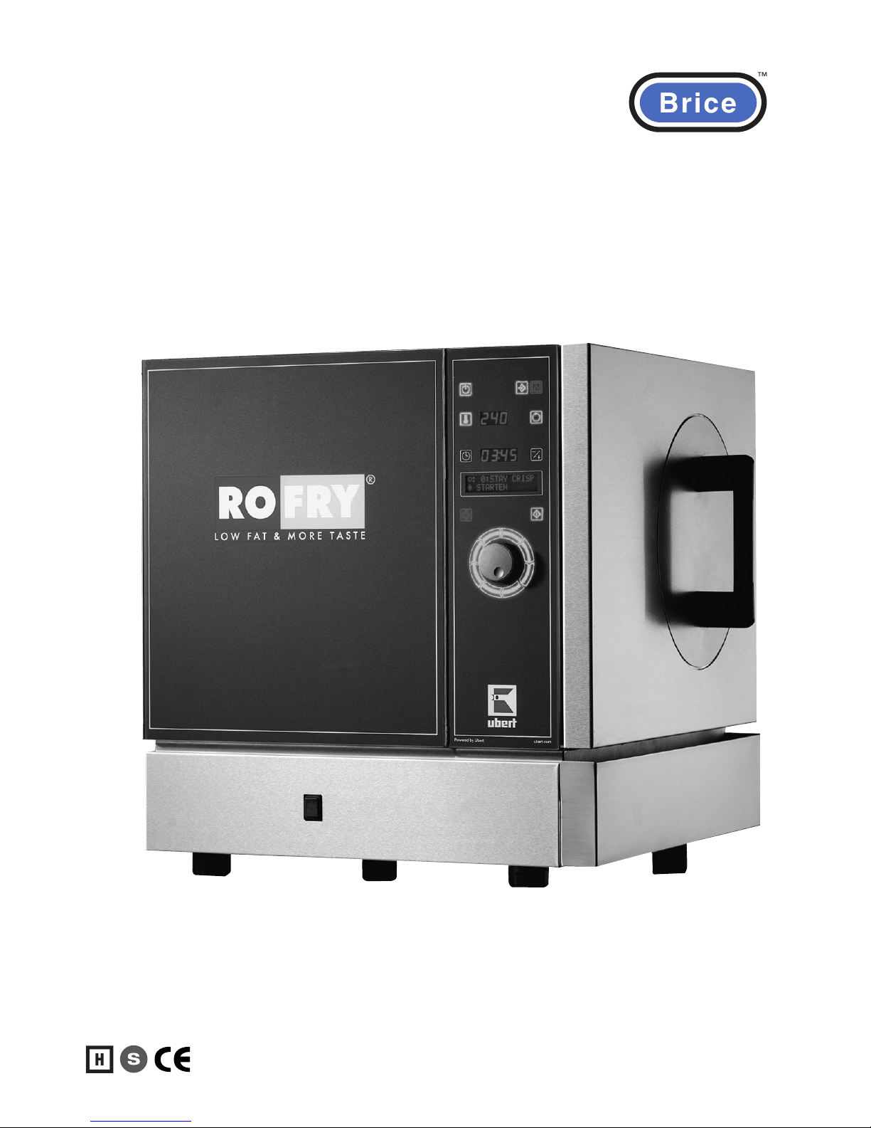
Operation and Safety Manual
Heavy Duty; Semi-Auto
Oven
Model
Rofry
®
Page 2

Error! Style not defined. 3
printed: 05/2013 Subject to change! RoFryUserManual.doc
1 Contents
1 Contents...................................................................................................................................... 3
2 Important References ................................................................................................................. 4
2.1 Fundamental Safety Notes................................................................................................... 4
2.2 Warranty and Liabilities........................................................................................................ 5
2.3 Symbols and Notes .............................................................................................................. 5
2.4 Copyright .............................................................................................................................. 5
2.5 Special Safety References................................................................................................... 6
3 Introduction ................................................................................................................................. 8
3.1 Introduction........................................................................................................................... 8
3.2 Special features.................................................................................................................... 8
3.3 Technical details................................................................................................................... 8
4 Installation and putting into operation ....................................................................................... 11
4.1 Unwrapping ........................................................................................................................ 11
4.2 Installation .......................................................................................................................... 11
4.3 Electrical connection .......................................................................................................... 11
4.4 Tap ..................................................................................................................................... 11
4.5 Sewage .............................................................................................................................. 12
4.6 Exhaust .............................................................................................................................. 12
4.7 Preparation of Using / Starting up ...................................................................................... 12
5 Operation .................................................................................................................................. 13
5.1 How RoFry
®
works ............................................................................................................. 13
5.2 Control Panel...................................................................................................................... 14
5.3 Description of operating elements...................................................................................... 16
5.4 Operation............................................................................................................................ 18
5.5 Programming...................................................................................................................... 19
6 Maintenance ............................................................................................................................. 21
6.1 Cleaning and Care ............................................................................................................. 21
6.2 Daily Cleaning .................................................................................................................... 22
6.3 Weekly Cleaning ................................................................................................................ 24
6.4 Trouble-Shooting................................................................................................................ 25
6.5 Wiring Diagram................................................................................................................... 26
6.6 Replacement of gaskets:.................................................................................................... 28
6.7 Spare Parts ........................................................................................................................ 31
6.8 Accessories ........................................................................................................................ 36
Page 3

4 Error! Style not defined.
printed: 05/2013 Subject to change! RoFryUserManual.doc
2 Important References
2.1 Fundamental Safety Notes
2.1.1 Consider notes in the operating manual
Precondition for the safe and trouble free use of this unit is the knowledge of the fundamental safety
notes and safety regulations.
The operating instruction contains the most important references to operate the unit safely.
These operating instructions, particularly the safety references, are to be considered by all persons,
who work on the unit.
Furthermore the rules and regulations to avoid accidents are to be considered.
2.1.2 Obligation of the operator
The Operator is obliged to only let persons work with the unit who:
• Are familiar with the fundamental regulations of work safety and accident avoiding and who have
been instructed how to operate the unit.
• Read and understood the chapter about safety and warning notes and have confirmed this with
their signature.
The safe conscious operation of the personnel has to be examined regularly.
2.1.3 Obligation of the personnel
All individuals who are authorized to work with the unit are obliged to:
• Pay attention to the fundamental regulations of work safety and accident avoiding,
• Read the chapter on work safety and warning notes in this manual and to confirm through their
signature that they have understood these, before actually operating the unit.
2.1.4 Possible risks
The RoFry
®
is built state of the art and in acknowledgement of all safety related rules. Nevertheless
is it possible that danger for body and lives of the user and/or third and/or impairments at the unit or
at other real values merge. The unit is to be used only :
• For the due use.
• In safety related flawless condition.
Disturbances which can hurt the safety are to be eliminated immediately.
2.1.5 Due use
Fundamentally our "General terms of sale and delivery" count. These are known to the operator at
the latest since signing of the contract. Claims to warranty and liability at persons- and property
damages are impossible, if they are to be led back to one or several of the following causes:
• Non due use of the unit.
• Improper assembling, starting up, operating and servicing of the unit.
• Operating the unit with defective safety devices or safety devices which have not been installed
properly and are in no working condition.
Page 4
Error! Style not defined. 5
printed: 05/2013 Subject to change! RoFryUserManual.doc
2.2 Warranty and Liabilities
Fundamentally our "General terms of sale and delivery" count. These are known to the operator at
the latest since signing of the contract. Claims to warranty and liability at persons- and property
damages are impossible, if they are to be led back to one or several of the following causes:
• Non due use of the unit.
• Improper assembling, starting up, operating and servicing of the unit.
• Operating the unit with defective safety devices or safety devices which have not been installed
properly and are in no working condition.
• Disobeying of the references in the operating manual concerning transportation storage, installation, start-up, operation, maintenance and assembling of the unit.
• Unauthorized mechanical or electrical changes of the unit.
• Insufficient maintenance of wear and tear parts.
• Unauthorized repair.
• Force of nature and act of god.
2.3 Symbols and Notes
In the operating manual the following symbols and signs are used:
This symbol means a possibly or directly threatening danger for the life and the
health of persons and/or a possibly dangerous situation.
Ignoring of these references may result in consequences for your health and/or can
lead to property damages!
This symbol points to important references for the proper use of the unit.
Not paying attention to these references can lead to disturbances at the unit or in
the environment!
This symbol points to operation tips and especially useful information.
Help for optimum use of all functions of the unit !
2.4 Copyright
The copyright on this operating manual remains at the company UBERT GASTROTECHNIK GMBH.
This operating manual is intended only for the operator and his personnel. It contains instructions
and references which neither completely nor partially:
• be duplicated
• be circulated
• be otherwise made available to third parties.
Offences may violate applicable laws.
Page 5

6 Error! Style not defined.
printed: 05/2013 Subject to change! RoFryUserManual.doc
2.5 Special Safety References
2.5.1 Safety devices
• Before operating the unit all protective devices like door and exhaust-cover as well
as all removable parts must be installed correctly and be fully workable.
• Protective devices may only be removed:
• After stand still and
• Prevention of unintentional restart.
• If partial components are delivered, an authorized staff member or service tech-
nician has to execute assembly according to installation guidelines.
2.5.2 Informal safety steps
• The operating manual is to be kept constantly accessible in the operating area.
• In addition to the operating manual all generally acknowledged and all local regula-
tions for accident avoiding and environmental protection have to be applied with.
• All safety- danger labels at the unit are to be kept in readable condition.
2.5.3 Education of the personnel
• Only trained and instructed personnel may work at the unit.
• The responsibilities of the personnel are to be determined clearly for installing, start-
up, operation, assembling, and servicing of the unit.
• During instruction the personnel may only work at the unit under supervision of an
experienced person.
2.5.4 Unit-control
Under no circumstances it is allowed to make changes to the source-code of the software!
Only instructed personnel are allowed to operate the controls.
2.5.5 Safety during regular operation
• The unit is only to operate if all protective devices are fully workable.
• Before starting the unit it is to ensure, that nobody becomes endangered by the start-
ing unit.
• At least once per shift the unit is to be examined with regard to visible damages and
functional ability of the safety devices.
2.5.6 Dangers caused by electric energy
• Any work on the electrical supply is to be executed only by a specialist.
• Likewise the electrical connection of this unit to the power supply must be executed
by an electro-specialist; the connection must follow the rules of the local determinations.
• The electric installation is to be examined regularly. Loose connections and brazed
cables are to be eliminated immediately.
• If works at any life-parts are necessary, a second person who switches off the main
switch if necessary is to consult.
2.5.7 Special danger-spots
• The basket and/or basket holder is to disassemble only at a switched off unit!
• Do not reach into the open, hot oven chamber!
• Do not touch the pulled out, hot basket during unloading!
• Do not reach into the hot exhaust!
2.5.8 Service and maintenance, troubleshooting
Page 6

Error! Style not defined. 7
printed: 05/2013 Subject to change! RoFryUserManual.doc
• Prescribed adjustment, service and inspection work is to be accomplished timely by
the manager or if necessary by an authorized service technician.
• The operating personnel is to be informed before the beginning of the maintenance
and service work.
• The unit is to be disconnected from the mains before maintaining, inspecting and
repairing is performed; the main switch is to be guarded against unintended pushing.
• Check all screw connections for tight fitting.
• After finishing maintenance check all safety devices for proper functionality.
2.5.9 Structural changes to the unit
• Do not perform any changes, extensions or conversions to the unit without the manu-
facturer’s permission, especially welding work at supporting parts.
• For all conversions a written permission of the company UBERT GASTROTECHNIK
GMBH is necessary.
• Change all parts of the unit, which are in improper condition.
• Use only original spare parts.
2.5.10 Cleaning of the unit and disposal of the waste
Used substances and materials are to be handled and disposed appropriately, especially
lubricants. Detergents have to follow the rules of food-hygiene
Page 7
8 Error! Style not defined.
printed: 05/2013 Subject to change! RoFryUserManual.doc
3 Introduction
3.1 Introduction
RoFry® offers due to its unique technology the possibility to fry regular products completely without
oil. The quality of the products fried without oil will always be the same high standard, no matter if
you take deep frozen or fresh goods, French fries or chicken nuggets, Asian specialties or fast food
products from USA.
The intelligent sensor avoids wrong handling and levels out different amounts and temperatures.
3.2 Special features
• compact design
• computer controlled
• self-diagnostic fault-finding-system
• easy to operate with two buttons
• no buying, storing, using and disposing of oil
• no tools are necessary to dismantle the machine for cleaning
• ideal size to install on a counter
• stainless steel design
• reduced emissions
• no need for fire-fighting appliances
3.3 Technical details
3.3.1 Capacity
The maximum capacity of RoFry
®
based on the product French fries is 2,5 kg deep frozen or fresh
products per load.
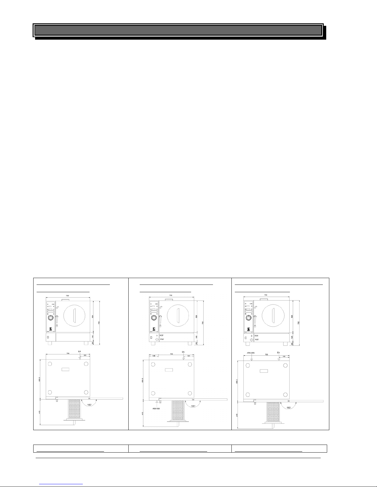
3.3.2 Dimensions [mm]
RF-300-ST (Front Loaded
Standard Version):
RF-300-TV (Front Loaded
Canister-Version):
RF-300-FC (Front Loading with
Water-Connection):
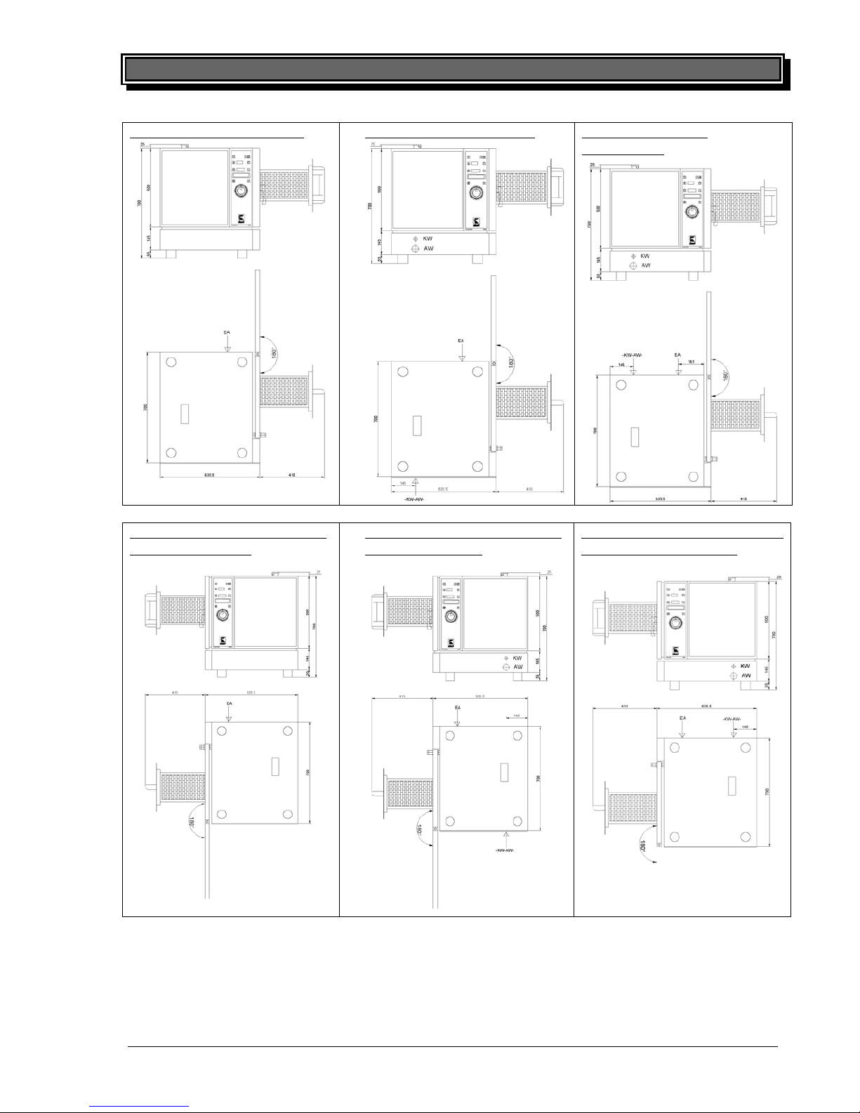
RF-330-ST (Right Hand
RF-330-TV (Right Hand RF-330-FC (Right Hand
Page 8
Error! Style not defined. 9
printed: 05/2013 Subject to change! RoFryUserManual.doc
Loaded Standard Version):
Loaded Canister-Version):
Loaded with WaterConnection):
RF-360-ST (Left Hand Loaded
Standard Version):
RF-360-TV (Left Hand Loaded
Canister-Version):
•RF-360-FC (Left Hand Loaded
with Water-Connection):
Page 9

10 Error! Style not defined.
printed: 05/2013 Subject to change! RoFryUserManual.doc
3.3.3 Weight
(Net weight)
Front Loaded Version RF-300-
ST Standard-Version app. 78kg
TV Canister -Version app. 88,5kg
FC Water-Connected Version app. 88,5kg
Right Hand Loaded Version RF-330-
ST Standard-Version app. 78kg
TV Canister-Version app. 88,5kg
FC Water-Connected Version app. 88,5kg
Left Hand Loaded Version RF-360-
ST Standard-Version app. 78 kg
TV Canister -Version app. 88,5kg
FC Water-Connected Version app. 88,5kg
3.3.4 Electrical details
Type Version Load per Ph:
RF-300/330/360-ST/TV/FC: Europe-Version
400V / 15,5kW / 50-60Hz / 3Ph with N 25 A
3.3.5 Noise emission
Type noise emission
all types < 70 dBA
Page 10
Error! Style not defined. 11
printed: 05/2013 Subject to change! RoFryUserManual.doc
4 Installation and putting into operation
In general all RoFry® units will be packed for safe transport after the final control in order to reac
h you properly. Nevertheless we ask you to have a look at the machine on
arrival to detect any transport damages.
Note! Visible damages have to be reported immediately!
4.1 Unwrapping
• Open the box and remove the wrapping carefully.
• Take out all movable parts and make sure that they are complete.
• Remove all cartons and folio around RoFry
®
• Pull the basket out of the unit with the black handle and remove all parts inside like operating
manual, legs, plugs etc.
4.2 Installation
• Install the legs and put the machine on the chosen place. Take care of the following points:
• The RoFry
®
has to be placed on a horizontal level. Small unevenness can be cor-
rected by the adjustable legs.
• Make sure that all ventilation holes have at least 5 cm clear space.
• There has to be enough free space to load, unload, clean and maintain the unit.
•
The machine has to be placed in a way that the complete area around it can be
cleaned easily.
4.3 Electrical connection
Note! While working on the unit with opened side-panels take care that the unit is dis-
connected from the mains. Even if the unit is switched off, the cooling fan may start to
run. Not paying attention may result in injury!
Please learn the electrical data of your unit from the nameplate. It is located at all types behind the
grease tray.
• Check whether your local electrical power supply is in accordance with the data on the name
plate.
• Make sure the supply cable is protected for units with a supply voltage as listed below:
≤ 240V (4/5-wire, min. cross-section 4) separately
with 40 Amps,
> 240V (4/5-wire, min. cross-section 2,5) separately
with 25 Amps
• Protection has to be done by use of a 3 pole line circuit breaker!
• The power supply needs to be manufactured from heat resistant, flexible cable. It is to be routed
to prevent any contact to hot parts.
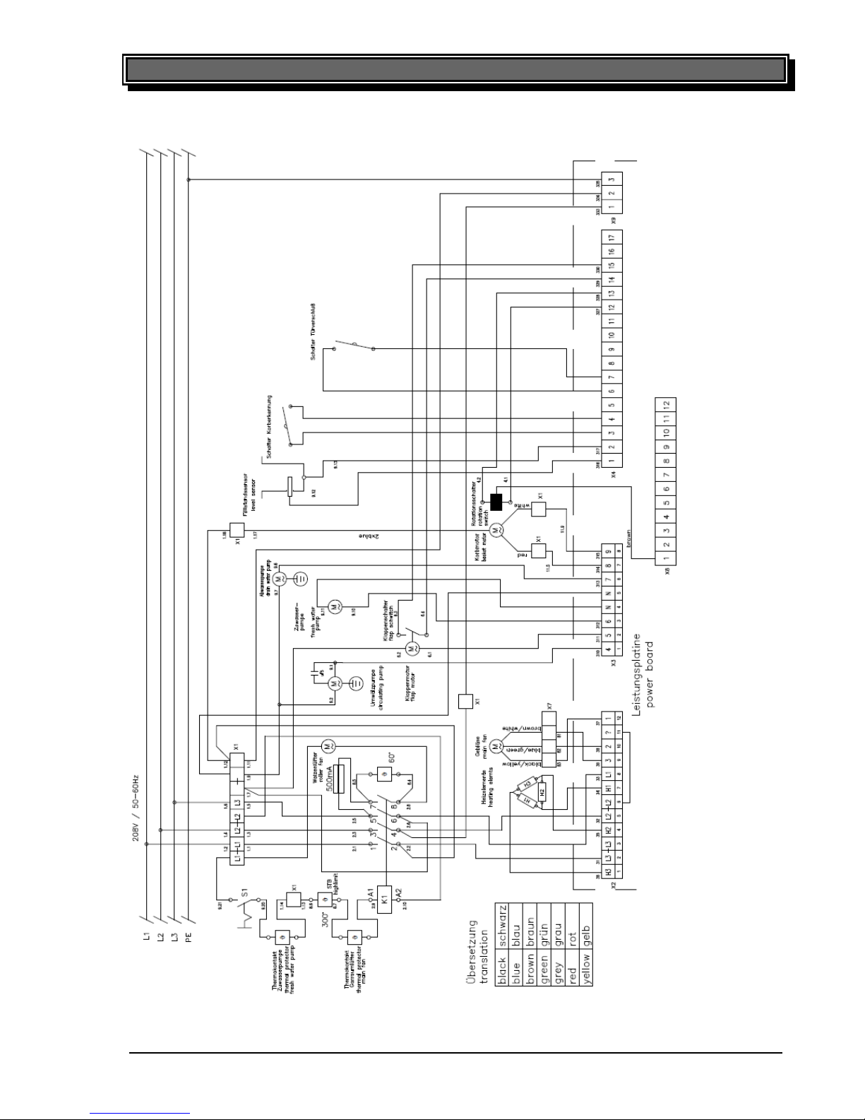
• For further information please see the wiring diagram (below)
Note! After the unit is connected to the mains, check correct
rotation direction of the
main fan: Remove the basket from the unit
(pull the basket out of the unit with the
black handle, push the release and remove the basket).
Switch the unit on and look
into the chamber. The fan wheel needs to rotate clockwise.
If the rotation direction is
wrong, change two phases on the main terminal block (X1).
After finishing any installation work, maintenance or repair,
check whether the ground
wires are connected properly to the casing and the side covers.
4.4 Tap
12 Error! Style not defined.
printed: 05/2013 Subject to change! RoFryUserManual.doc
Note! In general all Installation and Service work has to be done by an authorized
service technician! The following regulations have to be observed: DIN EN 1717 (alt
DIN 1988, Part4, technical regulations for drinking water installation/TRW.
• RoFry
®
requires a cold water connection; we recommend using a water-softening unit in case of
hard water above 8° dH (= Level 1).
• Use flexible pressure hose ½“ with ¾“ screw joint. A faucet as well as a flow-back-prevention has
to be provided on site.
• Water pressure should be between min. 100 kPa and max. 400 kPa. Use a pressure reducer in
case of water supply pressures above 400 kPa.
4.5 Sewage
Note! In general all Installation and Service work has to be done by an authorized serv-
ice technician! The following regulations have to be observed: DIN EN 1717 (alt DIN
1988, Part4, technical regulations for drinking water installation/TRW.
• The appliance needs an open sewage-connection, preferably ending in a funnel. UBERT recom-
mends a common flexible sewage-hose with ¾ “diameter to be fixed to the sewage connection
coming with the machine.
4.6 Exhaust
For an average capacity utilization of 60 % (equals a continual preparation of 1000g frozen goods
of -18°C) there is an amount of exhaust of app. 130 m³/h that contains 6 kg water as hot steam. The
steam has to be disposed by an extraction system. The best solution for this is an adequate hood-
system. If this is not possible because of the rooming situation other solutions can be found. In this
case please contact our service members they will be glad to assist you.
4.7 Preparation of Using / Starting up
Before you can use the RoFry® you have to clean all removable parts carefully with a grease sol-
vent.
Note! Do not use flammable cleaners. Do not use high-pressure-, water pressure- or
steam jet- cleaning devices. You will have further information about this in the section
”cleaning and up keeping”.
After cleaning the RoFry® properly the smell will be minimal when using it the first time.
Only for the Standard Version RF-3XX-ST:
Before using the RoFry
®
you should use the special RoFry® spray ”KOTE”. This is an anti adhesion
spray that prevents adhering of oil and food residues. Concerning this you will find more information
in the section ”cleaning and up keeping”.
Page 11
12 Error! Style not defined.
printed: 05/2013 Subject to change! RoFryUserManual.doc
Note! In general all Installation and Service work has to be done by an authorized
service technician! The following regulations have to be observed: DIN EN 1717 (alt
DIN 1988, Part4, technical regulations for drinking water installation/TRW.
• RoFry
®
requires a cold water connection; we recommend using a water-softening unit in case of
hard water above 8° dH (= Level 1).
• Use flexible pressure hose ½“ with ¾“ screw joint. A faucet as well as a flow-back-prevention has
to be provided on site.
• Water pressure should be between min. 100 kPa and max. 400 kPa. Use a pressure reducer in
case of water supply pressures above 400 kPa.
4.5 Sewage
Note! In general all Installation and Service work has to be done by an authorized serv-
ice technician! The following regulations have to be observed: DIN EN 1717 (alt DIN
1988, Part4, technical regulations for drinking water installation/TRW.
• The appliance needs an open sewage-connection, preferably ending in a funnel. UBERT recommends a common flexible sewage-hose with ¾ “diameter to be fixed to the sewage connection
coming with the machine.
4.6 Exhaust
For an average capacity utilization of 60 % (equals a continual preparation of 1000g frozen goods
of -18°C) there is an amount of exhaust of app. 130 m³/h that contains 6 kg water as hot steam. The
steam has to be disposed by an extraction system. The best solution for this is an adequate hoodsystem. If this is not possible because of the rooming situation other solutions can be found. In this
case please contact our service members they will be glad to assist you.
4.7 Preparation of Using / Starting up
Before you can use the RoFry® you have to clean all removable parts carefully with a grease solvent.
Note! Do not use flammable cleaners. Do not use high-pressure-, water pressure-
or
steam jet- cleaning devices. You will have further information about this in the sec
tion
”cleaning and up keeping”.
After cleaning the RoFry
®
properly the smell will be minimal when using it the first time.
Only for the Standard Version RF-3XX-ST:
Before using the RoFry
®
you should use the special RoFry® spray ”KOTE”. This is an anti adhesion
spray that prevents adhering of oil and food residues. Concerning this you will find more information
in the section ”cleaning and up keeping”.
Page 12
Error! Style not defined. 13
printed: 05/2013 Subject to change! RoFryUserManual.doc
5 Operation
5.1 How RoFry® works
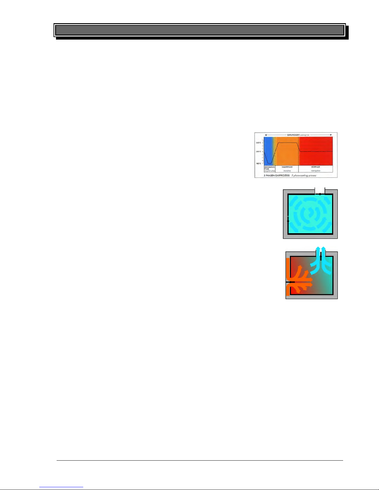
Once the device has been turned on, RoFry initializes. After pushing the STANDBY key is pushed,
RoFry enters the cold standby level. After confirming a program selection with the START key,
RoFry enters the hot standby level and is preheating to set temperature. This takes app. 2 minutes.
To fry food products, pull out the basket, put in the food to be prepared, push in the basket and push
the START key.
The basket starts to rotate and the main fan rotates full speed. The
air intake- and exhaust flaps are closed now. The temperature
drops. Now the computer control adjusts RoFry
®
automatically to
the amount and temperature of the food product by shortening or
lengthening the total cooking time to obtain a considerably even
product result.
The steam time phase starts. Now humidity is taken from the
product and turned into steam, cooking the product. During steam
time the temperatures in the chamber rise up to max. 20° C above
programmed operating temperature (if wanted). After the steam
time is finished, the flaps open again and the temperature will drop
to the start-level.
The roasting phase in which the goods get crispy begins. Now the
flaps are opened to let the vapor escape. Dry, preheated air is
blown via intake channel into the chamber. The flaps remain open
until the basket has been emptied.
14 Error! Style not defined.
printed: 05/2013 Subject to change! RoFryUserManual.doc
5.2 Control Panel
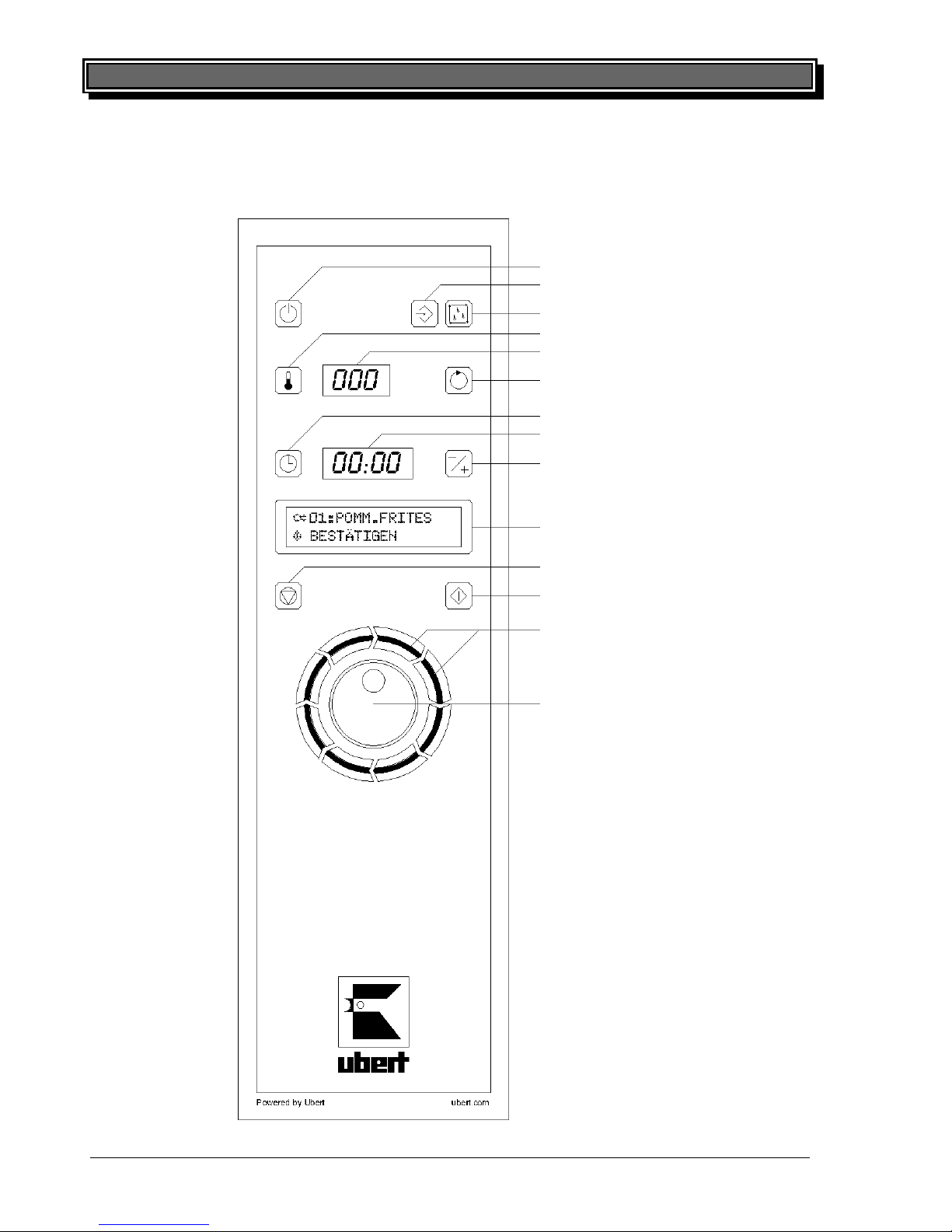
Following you will find an explanation a location of all components and their function to for optimum
use of RoFry
®
.
STANDBY
PROGRAMMING
CLEANING
TEMPERATURE
Temperature display
BASKET ROTATION
TIME
Time display
REFERENCE
Clear type display
STOP
START
Indicator LEDs
ENCODER knob
Page 13
14 Error! Style not defined.
printed: 05/2013 Subject to change! RoFryUserManual.doc
5.2 Control Panel
Following you will find an explanation a location of all components and their function to for optimum
use of RoFry
®
.
STANDBY
PROGRAMMING
CLEANING
TEMPERATURE
Temperature display
BASKET ROTATION
TIME
Time display
REFERENCE
Clear type display
STOP
START
Indicator LEDs
ENCODER knob
Page 14
Error! Style not defined. 15
printed: 05/2013 Subject to change! RoFryUserManual.doc
5.2.1 Function status of keys
To simplify operation of the RoFry, the function keys change colors to show their status.
Key LED off: Key cannot be selected (function is not available).
Key LED green: Key can be selected (function is available).
Key LED red: Key is selected (function is selected and active).
Indicator LEDs red spinning over green: A cooking program is running with basket rotation
Indicator LEDs flashing green: A cooking program is finished
5.2.2 Symbols of clear-type display
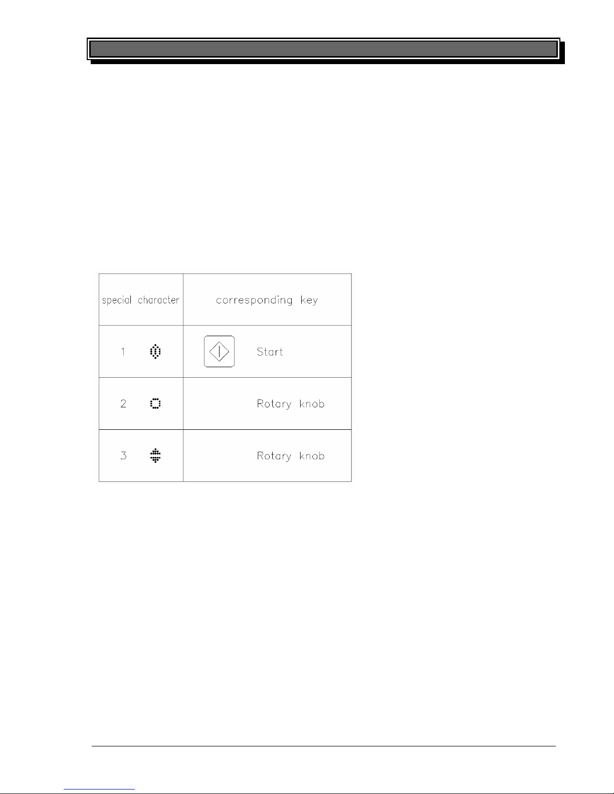
The following special characters (symbols) appear on the clear type display:
16 Error! Style not defined.
printed: 05/2013 Subject to change! RoFryUserManual.doc
5.3 Description of operating elements
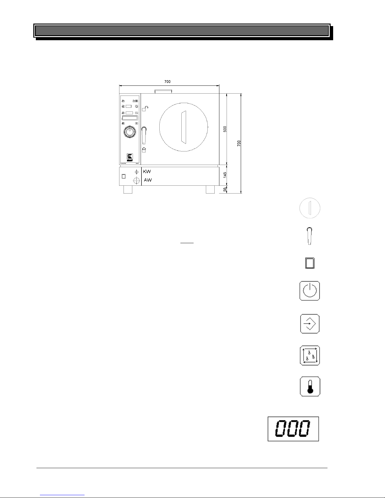
Following you will find the description of switches, keys, knob and displays
5.3.1 Basket handle
Pull out / push in the basket using the basket handle.
5.3.2 Door handle
NOTE: Only open the door using the door handle after the basket has been removed
completely from the equipment! Never use the door handle to carry the RoFry®!
5.3.3 Main switch
By pushing the main switch the device is being turned on or off.
5.3.4 STANDBY
By pushing the STANDBY key RoFry® will be activated (cold standby) and the program
that has been used the last time appears in the clear type display.
5.3.5 PROGRAMMING
By pushing the PROGRAMMING key the programming-mode will be activated and the
operator gets access to the programming-level.
5.3.6 CLEANING
By pushing the CLEANING key the cleaning-mode will be activated and the cleaning-
program that has been used the last time appears in the clear-type display.
5.3.7 TEMPERATURE
By pushing the TEMPERATURE key the set requested temperature of the current phase
appears on the Temperature display. The requested temperature appears as long as the
TEMPERATURE key is pushed.
5.3.8 Temperature display
Display of actual temperature or set temperature.
Page 15
16 Error! Style not defined.
printed: 05/2013 Subject to change! RoFryUserManual.doc
5.3 Description of operating elements
Following you will find the description of switches, keys, knob and displays
5.3.1 Basket handle
Pull out / push in the basket using the basket handle.
5.3.2 Door handle
NOTE: Only open the door using the door handle after
the basket has been removed
completely from the equipment! Never use the door handle to carry the RoFry
®
!
5.3.3 Main switch
By pushing the main switch the device is being turned on or off.
5.3.4 STANDBY
By pushing the STANDBY key RoFry
®
will be activated (cold standby) and the program
that has been used the last time appears in the clear type display.
5.3.5 PROGRAMMING
By pushing the PROGRAMMING key the programming-mode will be activated and the
operator gets access to the programming-level.
5.3.6 CLEANING
By pushing the CLEANING key the cleaning-mode will be activated and the cleaningprogram that has been used the last time appears in the clear-type display.
5.3.7 TEMPERATURE
By pushing the TEMPERATURE key the set requested temperature of the current phase
appears on the Temperature display. The requested temperature appears as long as the
TEMPERATURE key is pushed.
5.3.8 Temperature display
Display of actual temperature or set temperature.
Page 16
Error! Style not defined. 17
printed: 05/2013 Subject to change! RoFryUserManual.doc
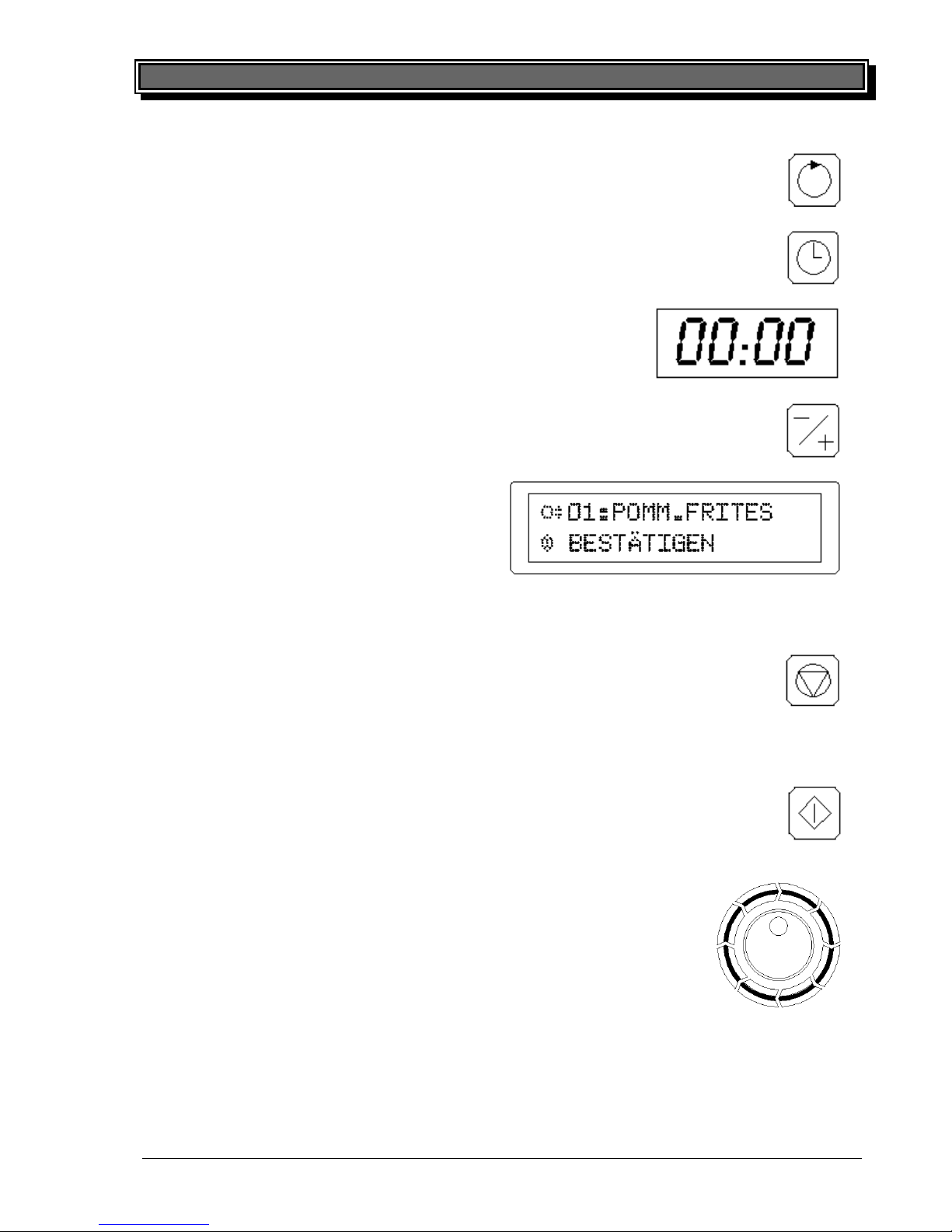
5.3.9 BASKET ROTATION
By pushing the ROTATION key the basket can be turned again after the regular emptying if necessary.
5.3.10 TIME
By pushing the TIME key the set time of the current phase is displayed on the Time
display. The set time appears as long as the TIME key is pushed.
5.3.11 Time display
Display of remaining time, set time and reference time.
5.3.12 REFERENCE
By pushing the REFERENCE key in standby mode, the reference time of the selected
program is shown on the Time display.
5.3.13 Clear type display
In the first line of the Clear type display the current program is shown. The second line shows
the current status of the program or a menudriven demand for further necessary operation
steps.
In the programming-mode the first line of the clear-type display shows the program level and
name. The second line asks for choosing of functions and input of values by the encoder
5.3.14 STOP
Push the STOP key to:
- Interrupt a currently running program.
- Deselect the program during hot standby.
- Quit programming in the programming level and jump back to the cold standby.
- Leave the programming level.
5.3.15 START
Push the START key to:
- Confirm selection of a program during cold standby.
- Start a program during hot standby.
5.3.16 ENCODER
By actuating the ENCODER all programs, menu points, temperatures, times,
basket rotation, automatic functions and volume control can be selected and
adjusted. When the ENCOEDER is turned clockwise the programs and menu
points are displayed numerically on the clear type display In case of turning
anticlockwise this is happening numerically reverse.
18 Error! Style not defined.
printed: 05/2013 Subject to change! RoFryUserManual.doc
5.4 Operation
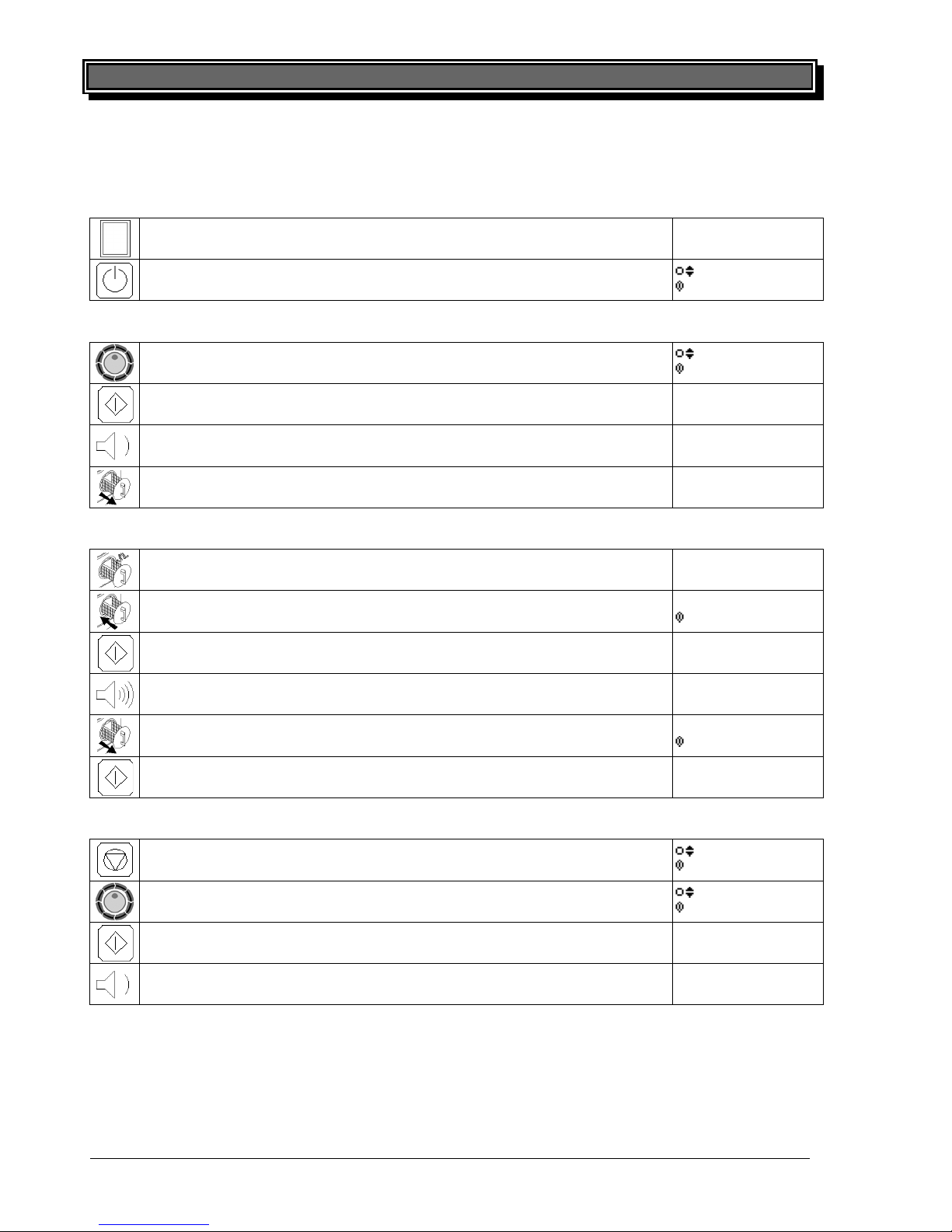
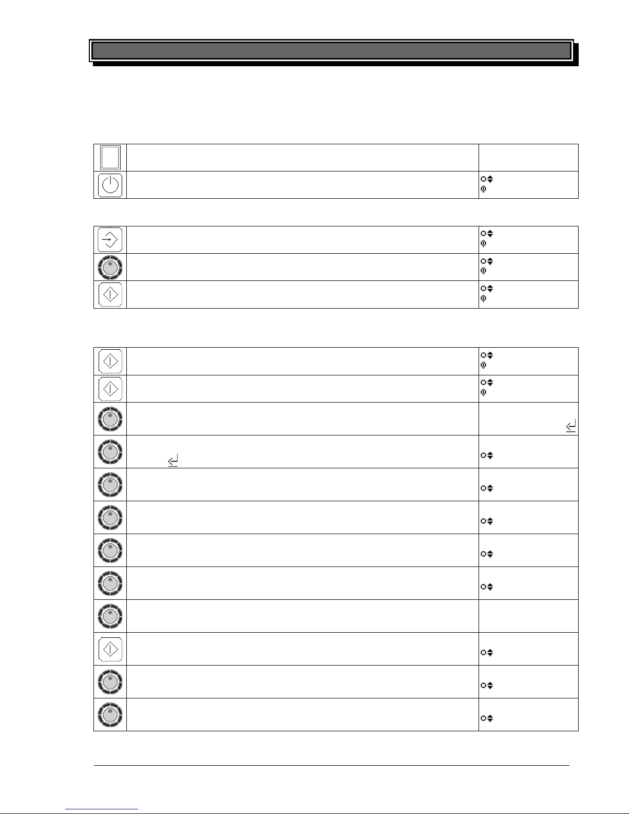
5.4.1 Activate equipment
Press main switch
INITIALIZING
Press STAND-BY key (as soon as it lights up green)
02:CHICK.NUGG.
CONFIRM
5.4.2 Select program
Select desired program by ENCODER
01:CHIPS
CONFIRM
Confirm selected program by START key
01:CHIPS
PREHEAT
Equipment heats up approx. 2-3 min.
01:CHIPS
STAND BY
Afterwards pull out the basket to the end stop
01:CHIPS
STAND BY
5.4.3 Frying
Fill in product
01:CHIPS
STAND BY
Push in the basket
01:CHIPS
START?
Start program by START key (not with AUTOSTART)
01:CHIPS
PROGRAM RUNS
Program runs until signal sounds
01:CHIPS
READY
Pull out the basket to the end stop
01:CHIPS
EMPTY
Empty basket by START key (not with AUTOEMPTY)
01:CHIPS
STAND BY
5.4.4 Switch between programs
Leave current program by STOP key
01:CHIPS
CONFIRM
Select desired program by ENCODER
02:CHICK.NUGG.
CONFIRM
Confirm selected program by START key
02:CHICK.NUGG.
PREHEAT
Equipment heats up a few seconds if necessary (continue with ”Fry-
ing“)
02:CHICK.NUGG.
STAND BY
Page 17
18 Error! Style not defined.
printed: 05/2013 Subject to change! RoFryUserManual.doc
5.4 Operation
5.4.1 Activate equipment
Press main switch
INITIALIZING
Press STAND-BY key (as soon as it lights up green)
02:CHICK.NUGG.
CONFIRM
5.4.2 Select program
Select desired program by ENCODER
01:CHIPS
CONFIRM
Confirm selected program by START key
01:CHIPS
PREHEAT
Equipment heats up approx. 2-3 min.
01:CHIPS
STAND BY
Afterwards pull out the basket to the end stop
01:CHIPS
STAND BY
5.4.3 Frying
Fill in product
01:CHIPS
STAND BY
Push in the basket
01:CHIPS
START?
Start program by START key (not with AUTOSTART)
01:CHIPS
PROGRAM RUNS
Program runs until signal sounds
01:CHIPS
READY
Pull out the basket to the end stop
01:CHIPS
EMPTY
Empty basket by START key (not with AUTOEMPTY)
01:CHIPS
STAND BY
5.4.4 Switch between programs
Leave current program by STOP key
01:CHIPS
CONFIRM
Select desired program by ENCODER
02:CHICK.NUGG.
CONFIRM
Confirm selected program by START key
02:CHICK.NUGG.
PREHEAT
Equipment heats up a few seconds if necessary (continue with ”Frying“)
02:CHICK.NUGG.
STAND BY
Page 18
Error! Style not defined. 19
printed: 05/2013 Subject to change! RoFryUserManual.doc
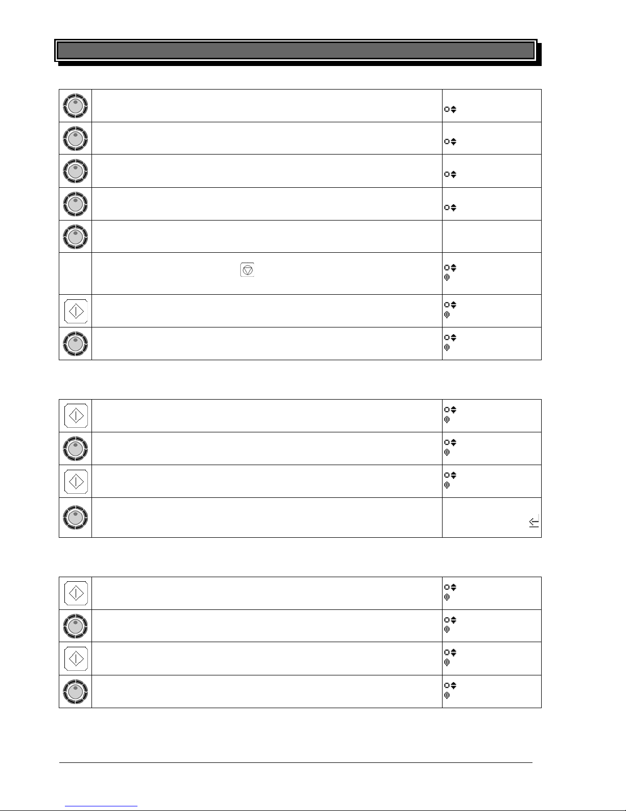
5.5 Programming
5.5.1 Activate equipment
Press main switch
INITIALIZING
Press STAND-BY key (as soon as it lights up green)
02:CHICK.NUGG.
CONFIRM
5.5.2 Enter programming level
Push and hold programming button (at least 3 seconds)
CODE: 127
CONFIRM
Select code “100“ by ENCODER (100 is the factory default and could
have been changed!)
CODE: 100
CONFIRM
Confirm selected code by START key
PROGRAM ROFRY
CONFIRM
5.5.3 Enter new program
Presuming the programming level has already been entered
Confirm“PROGRAM ROFRY“ by START key
NEW PROG:
CONFIRM
Confirm“NEW PROG:“ by START key
08:POMMES FEIN
CONFIRM
Select product name
Confirm by START key
POMMES FEIN
6789_-+/().:<-->
If applicable, edit Product name by cursor, then move most right and
Confirm by START key
08:FRIES
STEAM TEMP.
Adjust the steam temperature shown in the temperature display.
Confirm by START key
08: FRIES
STEAM TIME
Adjust the steam time shown in the time display.
Confirm by START key
08: FRIES
ROASTING TEMP
Adjust the roasting temperature shown in the temperature display.
Confirm by START key
08: FRIES
RÖST ZEIT
Adjust the roasting time shown in the time display.
Confirm by START key
08: FRIES
OPTIONS N
To enter Options change to “OPTIONS Y”
Confirm by START key
08: FRIES
BATCH REFERENCE
Time for Batch Reference is “00:00“ in the time display.
Confirm by START key
08: FRIES
+FACTOR
Adjust +Factor shown in temperature display to “075“ by ENCODER
Confirm by START key
08: FRIES
-FACTOR
Adjust -Factor shown in temperature display to “075“ by ENCODER
Confirm by START key
08: FRIES
AUTOSTART N
20 Error! Style not defined.
printed: 05/2013 Subject to change! RoFryUserManual.doc
Activate AUTOSTART by selecting(“Y“) or deactivate (“N“)
Confirm by START key
08: FRIES
AUTOEMPTY N
Activate AUTOEMPTY by selecting(“Y“) or deactivate (“N“)
Confirm by START key
08: FRIES
BASKET ROT. Y
Activate Basket Rotation (“Y“) or deactivate by selecting (“N“)
Confirm by START key
08: FRIES
ROT. DELAY
Adjust Rotation Delay shown in the Time display
Confirm by START key
08: FRIES
ROT. INTERVAL
Adjust Rotation Interval shown in the Time display
Confirm by START key
08: FRIES
STORE DATA
RoFry is storing the cooking program settings
(NOTE: In case the STOP key is pushed before the message
“STORE DATA” appears, all settings made so far, will get lost.
PROGRAM ROFRY
CONFIRM
To write /change / delete another cooking program:
Confirm“PROGRAM ROFRY“ by START key
09:POMMES FEIN
CONFIRM
To leave the programming level select “EXIT”.
Confirm by START key
EXIT
CONFIRM
5.5.4 Change a program
Presuming the programming level has already been entered
Confirm“PROGRAM ROFRY“ by START key
NEW PROG:
CONFIRM
Select “CHANGE PROG.“
CHANGE PROG.
CONFIRM
Confirm by START key
01:NUGGETS
CONFIRM
Select the cooking program to be changed
Confirm by START key >Refer to the chapter “Enter new pro-
gram“(above) for further steps
NUGGETS
6789_-+/().:<-->
5.5.5 Delete a program
Presuming the programming level has already been entered
Confirm“PROGRAM ROFRY“ by START key
NEW PROG:
CONFIRM
Select “DELTE PROG.“
DELTE PROG.
CONFIRM
Confirm by START key
01:NUGGETS
CONFIRM
Select the cooking program to be deleted
Confirm by START key
PROGRAM ROFRY
CONFIRM
Page 19
20 Error! Style not defined.
printed: 05/2013 Subject to change! RoFryUserManual.doc
Activate AUTOSTART by selecting(“Y“) or deactivate (“N“)
Confirm by START key
08: FRIES
AUTOEMPTY N
Activate AUTOEMPTY by selecting(“Y“) or deactivate (“N“)
Confirm by START key
08: FRIES
BASKET ROT. Y
Activate Basket Rotation (“Y“) or deactivate by selecting (“N“)
Confirm by START key
08: FRIES
ROT. DELAY
Adjust Rotation Delay shown in the Time display
Confirm by START key
08: FRIES
ROT. INTERVAL
Adjust Rotation Interval shown in the Time display
Confirm by START key
08: FRIES
STORE DATA
RoFry is storing the cooking program settings
(NOTE: In case the STOP key is pushed before the message
“STORE DATA” appears, all settings made so far, will get lost.
PROGRAM ROFRY
CONFIRM
To write /change / delete another cooking program:
Confirm“PROGRAM ROFRY“ by START key
09:POMMES FEIN
CONFIRM
To leave the programming level select “EXIT”.
Confirm by START key
EXIT
CONFIRM
5.5.4 Change a program
Presuming the programming level has already been entered
Confirm“PROGRAM ROFRY“ by START key
NEW PROG:
CONFIRM
Select “CHANGE PROG.“
CHANGE PROG.
CONFIRM
Confirm by START key
01:NUGGETS
CONFIRM
Select the cooking program to be changed
Confirm by START key >Refer to the chapter “Enter new program“(above) for further steps
NUGGETS
6789_-+/().:<-->
5.5.5 Delete a program
Presuming the programming level has already been entered
Confirm“PROGRAM ROFRY“ by START key
NEW PROG:
CONFIRM
Select “DELTE PROG.“
DELTE PROG.
CONFIRM
Confirm by START key
01:NUGGETS
CONFIRM
Select the cooking program to be deleted
Confirm by START key
PROGRAM ROFRY
CONFIRM
Page 20
Error! Style not defined. 21
printed: 05/2013 Subject to change! RoFryUserManual.doc
6 Maintenance
Following some advises concerning maintenance, care, trouble shooting and service for RoFry®.
6.1 Cleaning and Care
6.1.1 Safety advices
• Do not use inflammable detergents cleaners. Never use high-pressure, water
pressure- or steam jet- cleaning devices.
• Wear fire-safe, insulated gloves to prevent burnings when touching hot parts.
• Wear acid-proof gloves while cleaning the cold parts to prevent skin irritations.
6.1.2 General recommendations
• The unit has to be cleaned daily.
• Only use cleaners that are appropriate for food (neutral or alkaline detergents),
even if there are plain and persistent residues.
• After cleaning with special cleaners you have to wash all parts with clear water and
dry them afterwards so that there are no residues of the cleaner on these parts.
• It is absolutely necessary to watch out for some fundamental things to keep this
long-lived high-grade-steel-device working:
- always keep the high-grade-steel surface clean.
- watch out that there is always enough fresh air on the surface
- never contact the surface with rusty material
• Never use bleaching or chlorine cleaners.
6.1.3 Detergents
To make the cleaning fast and easy we have integrated some cleaners in our program:
For TV/FC- Version
• RoFry
®
-Cleaner
• RoFry
®
-Descaler
• Stainless steel-cleaner:
You have to spray this from a distance of app. 25 cm on the surface and wipe it off
with a dry cleaning rag. If you want to clean only small parts you have to spray it directly on the cleaning rag and wipe it off this way. With this method it is possible to
clean RoFry
®
easily and without stripes.
For ST- Version:
• RoFry
®
-Spray ‘KOTE’:
By using this spray a film is built up that prevents that any particles of the food,
grease, oil etc. can stick on the surface.
Note! Never use KOTE for the basket and the basketholder.
• Soak-Tank:
This is for cleaning of all removable parts except the fresh air filter.
Page 21
22 Error! Style not defined.
printed: 05/2013 Subject to change! RoFryUserManual.doc
6.1.4 RoFry®-spray ‘KOTE’ (ST-Version)
KOTE creates a film that prevents that sediments of food will bake on the surface of parts. The film
sticks to the parts during the cooking and so there will be no dirt on these parts.
KOTE is tested and licensed for food equipment.
KOTE is not to use with parts which have direct food contact. (e.g.: basket or basketholder).
Using advices:
• Parts to be sprayed are: chamber walls (incl. inside of door), air guide, lamella sheet, fan wheel.
• Before spraying the film on these parts, they have to be cooled down, cleaned and dried.
• Shake the spray thoroughly and spread evenly on the parts. Do not wipe away the film!
• After spraying the parts, RoFry has to be heated up to 230°C and has to maintain this tempera-
ture for about 5 minutes. The film will dry fully for the optimal function.
• To clean the parts, you just take a wet rag and some water. Extreme dirt can be washed away
with a sponge.
6.2 Daily Cleaning
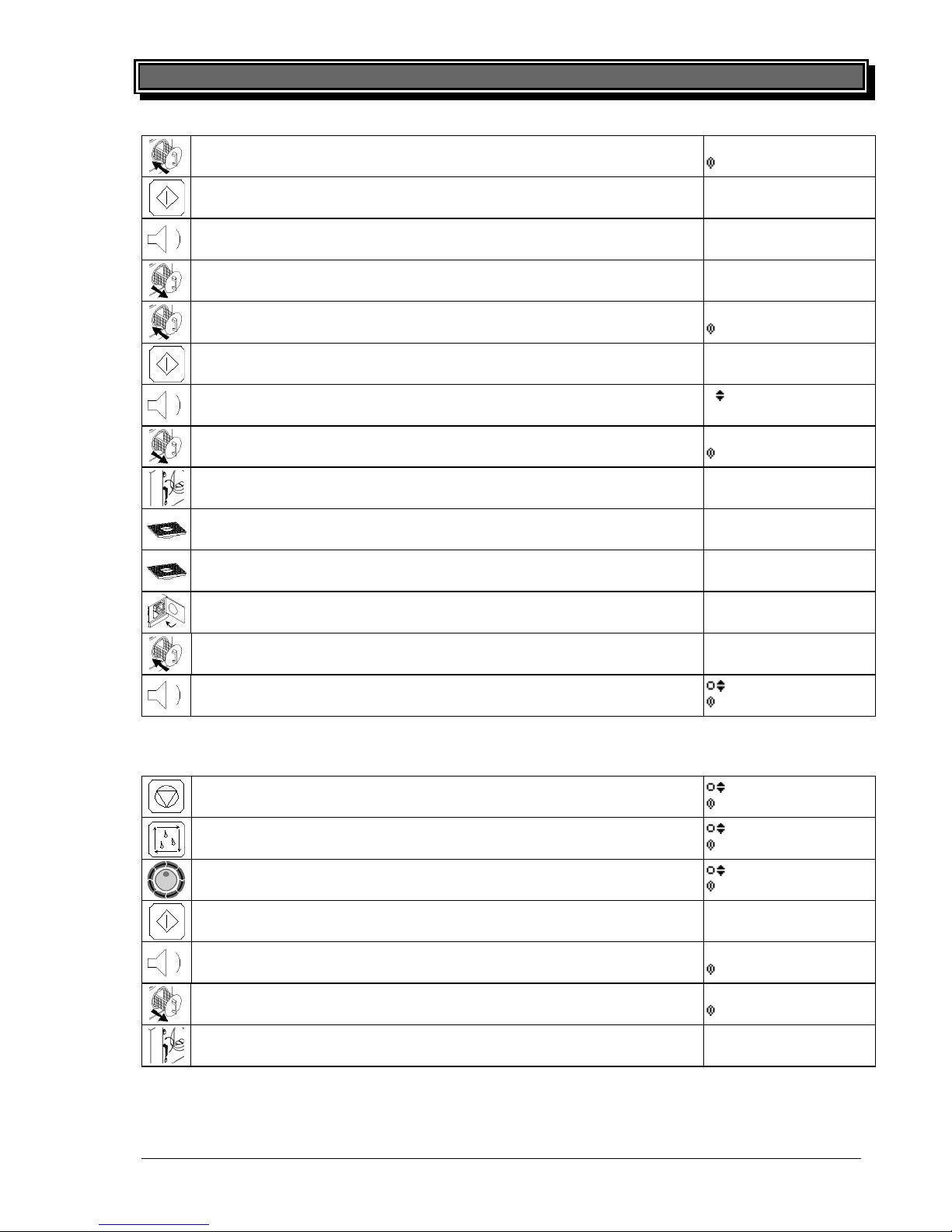
6.2.1 RoFry® with ASC (FC & TV-Version)
The ASC (automatic self cleaning) system of RoFry provides several cleaning programs:
- CLEAN SHORT -> suitable for light dirty conditions only
- CLEAN NORMAL -> for the typical daily cleaning
- DECALCIFY -> to thoroughly remove lime inside the RoFry
- OPEN DOOR -> for the manual daily and for the weekly cleaning
- PUMP OUT -> to pump out any liquid residues remained in the RoFry after an unintended
interruption of a cleaning cycle (eg. circuit breaker had tripped)
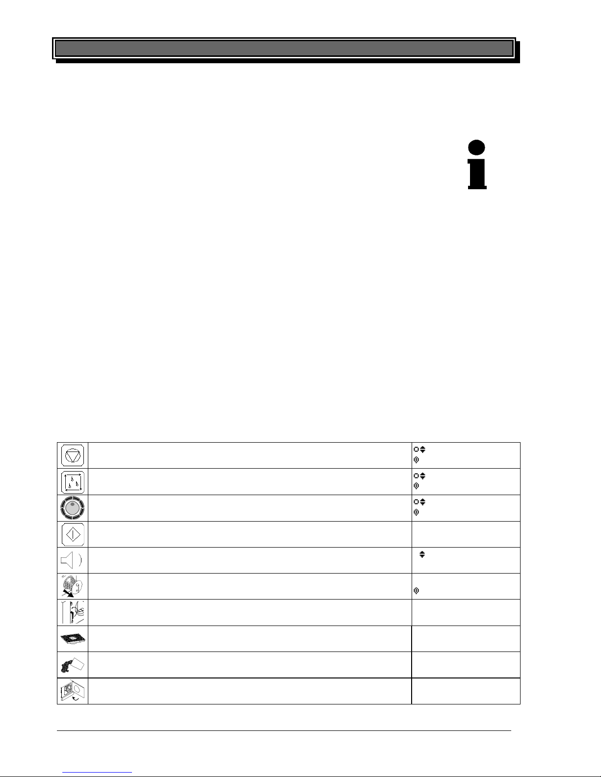
The following procedure explains step by step how to clean RoFry with ASC
Leave current frying-program by STOP key
01:CHIPS
CONFIRM
Enter cleaning mode by CLEANING key
CLEAN SHORT
CONFIRM
Select desired program by ENCODER
CLEAN NORMAL
CONFIRM
Confirm selected program by START key
CLEAN NORMAL
COOL DOWN
RoFry
®
cools down for approx. 15-20 min.
CLEAN NORMAL
REMOVE BASKET
Remove basket completely
CLEAN NORMAL
OPEN THE DOOR
Open door / Remove basket-holder, lamella-sheet, strainer
CLEAN NORMAL
EMPTY STRAINER
Remove crumbs from gaskets and bottom of chamber, empty
strainer
CLEAN NORMAL
EMPTY STRAINER
Insert strainer + lamella sheet, fill in cleaner, insert basket-holder
CLEAN NORMAL
EMPTY STRAINER
Close the door
CLEAN NORMAL
INSERT BASKET
Page 22
Error! Style not defined. 23
printed: 05/2013 Subject to change! RoFryUserManual.doc
Insert basket completely
CLEAN NORMAL
START ?
Start selected program by START key
CLEAN NORMAL
PROGRAM RUNS
Program runs until signal sounds
01:CHIPS
REMOVE BASKET
Remove basket completely, fill in rinser
CLEAN NORMAL
RINSER
Insert basket completely
CLEAN NORMAL
CONTINUE
Continue program by START key
CLEAN NORMAL
PROGRAM RUNS
Program runs until signal sounds
CLEAN NORMAL
REMOVE BASKET
Remove basket completely
CLEAN NORMAL
OPEN THE DOOR
Open door / Remove basket-holder, lamella-sheet, strainer
CLEAN NORMAL
EMPTY STRAINER
Empty strainer / wipe gaskets thoroughly
CLEAN NORMAL
EMPTY STRAINER
Insert strainer, lamella-sheet and basket-holder
CLEAN NORMAL
EMPTY STRAINER
Close the door
CLEAN NORMAL
INSERT BASKET
Insert basket completely
CLEAN NORMAL
DRYING
Program runs off to signal, RoFry
®
jumps back to frying-mode
01:POMM.FRITES
CONFIRM
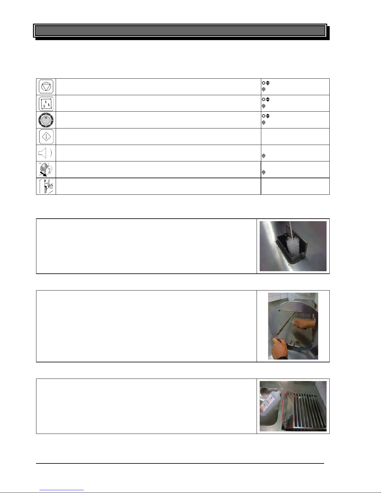
6.2.2 RoFry® without ASC (ST-Version)
The following procedure explains step by step how to clean RoFry without ASC
Leave current frying-program by STOP key
01:CHIPS
CONFIRM
Enter cleaning mode by CLEANING key
01:CLEAN SHORT
START?
Select the OPEN DOOR program by ENCODER
:OPEN DOOR
START?
Confirm selected program by START key
OPEN DOOR
COOL DOWN
RoFry
®
cools down for approx. 15-20 min.
OPEN DOOR
OPEN THE DOOR
Remove basket completely
OPEN DOOR
OPEN THE DOOR
Open the door and switch off RoFry
Remove all interior parts of RoFry and clean them thoroughly.
If applicable, use the RoFry SOAK TANK. Refer to the soak tanks manual for further instructions.
Page 23
24 Error! Style not defined.
printed: 05/2013 Subject to change! RoFryUserManual.doc
6.3 Weekly Cleaning
Beside the Daily cleaning the following items need some special care on a weekly basis:
Leave current frying-program by STOP key
01:CHIPS
CONFIRM
Enter cleaning mode by CLEANING key
01:CLEAN SHORT
START?
Select the OPEN DOOR program by ENCODER
:OPEN DOOR
START?
Confirm selected program by START key
OPEN DOOR
COOL DOWN
RoFry
®
cools down for approx. 15-20 min.
OPEN DOOR
OPEN THE DOOR
Remove basket completely
OPEN DOOR
OPEN THE DOOR
Open the door and switch off RoFry
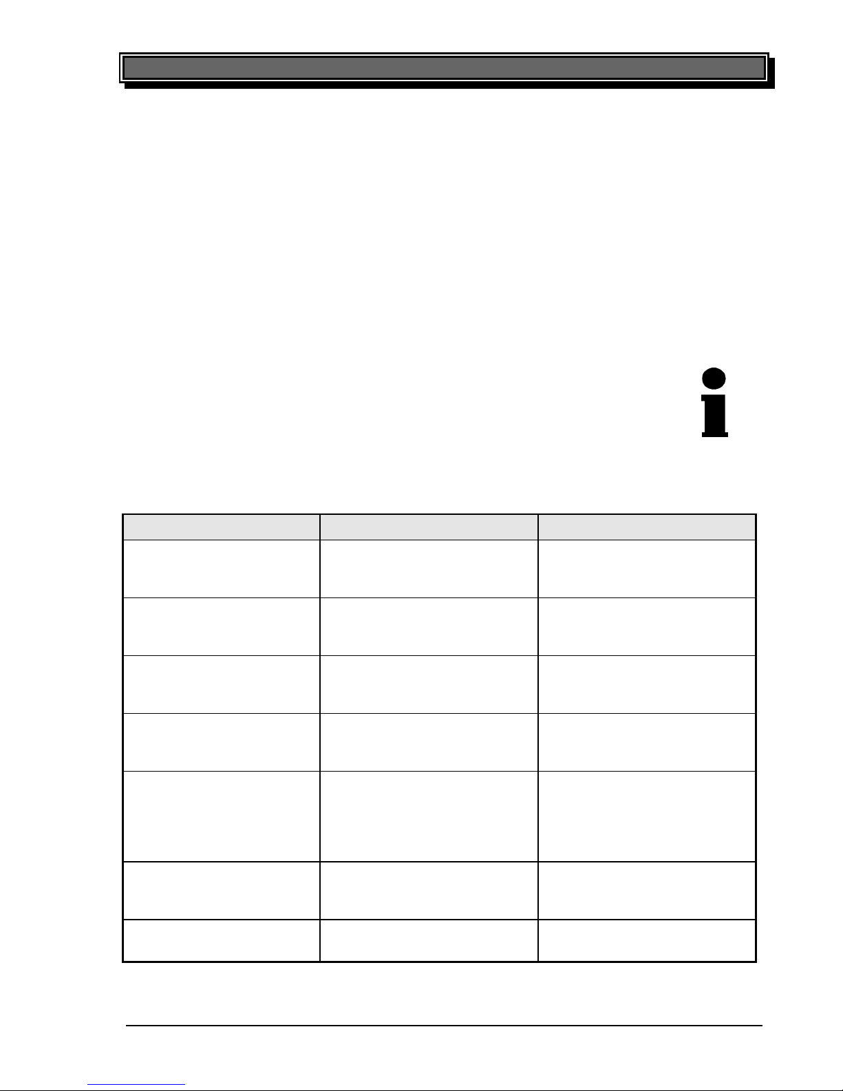
6.3.1 Flap
Clean the area around the flap as well as the air intake and exhaust channel
thoroughly.
6.3.2 Sliders
Clean the groove in both sliders of the basket holder with a flat screwdriver
thoroughly to ensure easy sliding of the basket.
6.3.3 Particle separator (lamella sheet)
Use the lime remover to thoroughly decalcify the bottom side of the lamella
sheet.
Page 24
Error! Style not defined. 25
printed: 05/2013 Subject to change! RoFryUserManual.doc
6.4 Trouble-Shooting
If your RoFry® does not work satisfactorily we would like to give a first help with the following checklist. Only after checking these points you should contact:
a) Your responsible service partner
or
b) Directly the company: UBERT GASTROTECHNIK GmbH
Werk II Gewerbegebiet Nord
Vennekenweg 17
46348 Raesfeld
Tel.:(49) 02865 / 602-226
Service-Tel.:0172 / 2 82 86 31
Fax:(49) 02865 / 602-102 (or -103)
Only the
se two companies are allowed to carry out service work and replacement of
defect parts. If you do not observe this note or in case of manipulation of a third party
any claims for guarantee will become invalid!
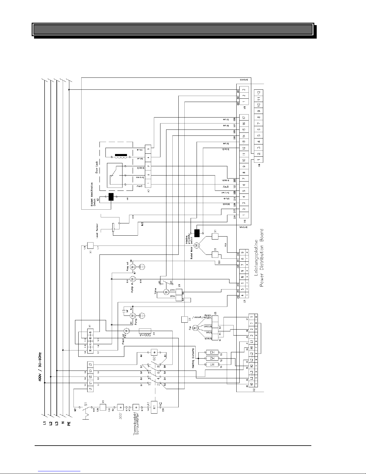
6.4.1 Malfunction check list
In case you encounter problems in reaching the desired product quality, please check the programming parameter following this checklist
problem possible cause remedy
food does not become crispy frying time too short
temperature too low
steam-time too long
extend processing time
increase temperature
shorten steam-time
food does not become crispy
even after changing the parameters
fan wheel does not turn clockwise
control sense has to be changed
(Service)
food becomes too crispy frying time too long
temperature too high
steam-time too short
shorten frying time
lower temperature
extend steam-time
food becomes too crispy
even after changing the parameters
malfunction of valves call service
parameters for average
amount are programmed
correctly but the device does
not recognize different
amounts
correction factors are not
adapted correctly
adapt correction factors
error waste water waste water hose bent
waste water hose clogged
waste water pump defective
check waste water hose
clean waste water hose
inform service company
leakage at basket- and doorgasket
basket- and door- gasket defective or perished
change gaskets following service
advice
Page 25
26 Error! Style not defined.
printed: 05/2013 Subject to change! RoFryUserManual.doc
6.5 Wiring Diagram
6.5.1 RF-300/330/360-ST/TV/FC 400V / 50-60Hz / 3Ph with N
Page 26
Error! Style not defined. 27
printed: 05/2013 Subject to change! RoFryUserManual.doc
6.5.2 RF-300/330/360-ST/TV/FC 208V / 50-60Hz / 3Ph without N
Page 27
28 Error! Style not defined.
printed: 05/2013 Subject to change! RoFryUserManual.doc
6.6 Replacement of gaskets:
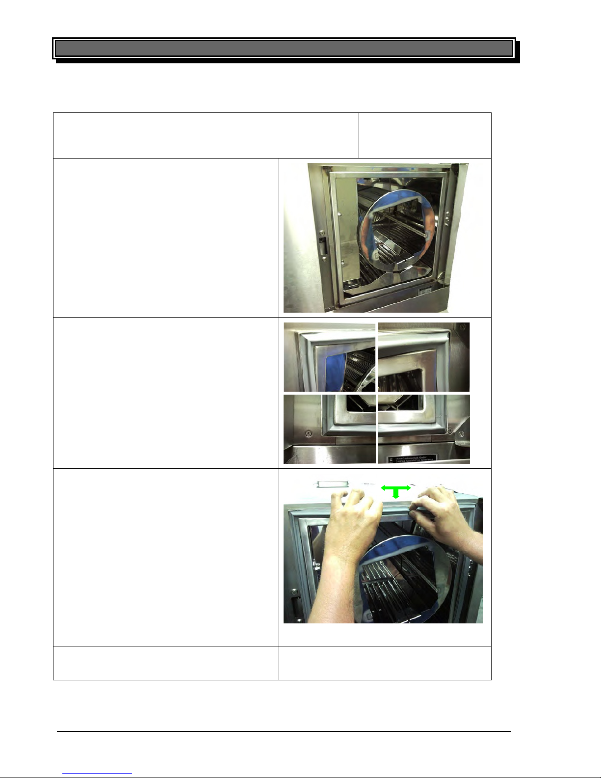
1. Select the program „OPEN DOOR“, while in Cleaning mode.
The unit cools down below 50°C; remove the basket and then
open the door. Switch off the RoFry
®
at the main switch.
OPEN DOOR
START?
2. Remove the old gasket by pulling it out and
clean the notch of the seal; remove grease
and other residues.
3. Assemble in the new seal. Start with the 4
corners.
4. Push the seal into the notch. Start in the
middle of each side and work your way to
the corners. Make sure neither to stretch nor
to forge the seal.
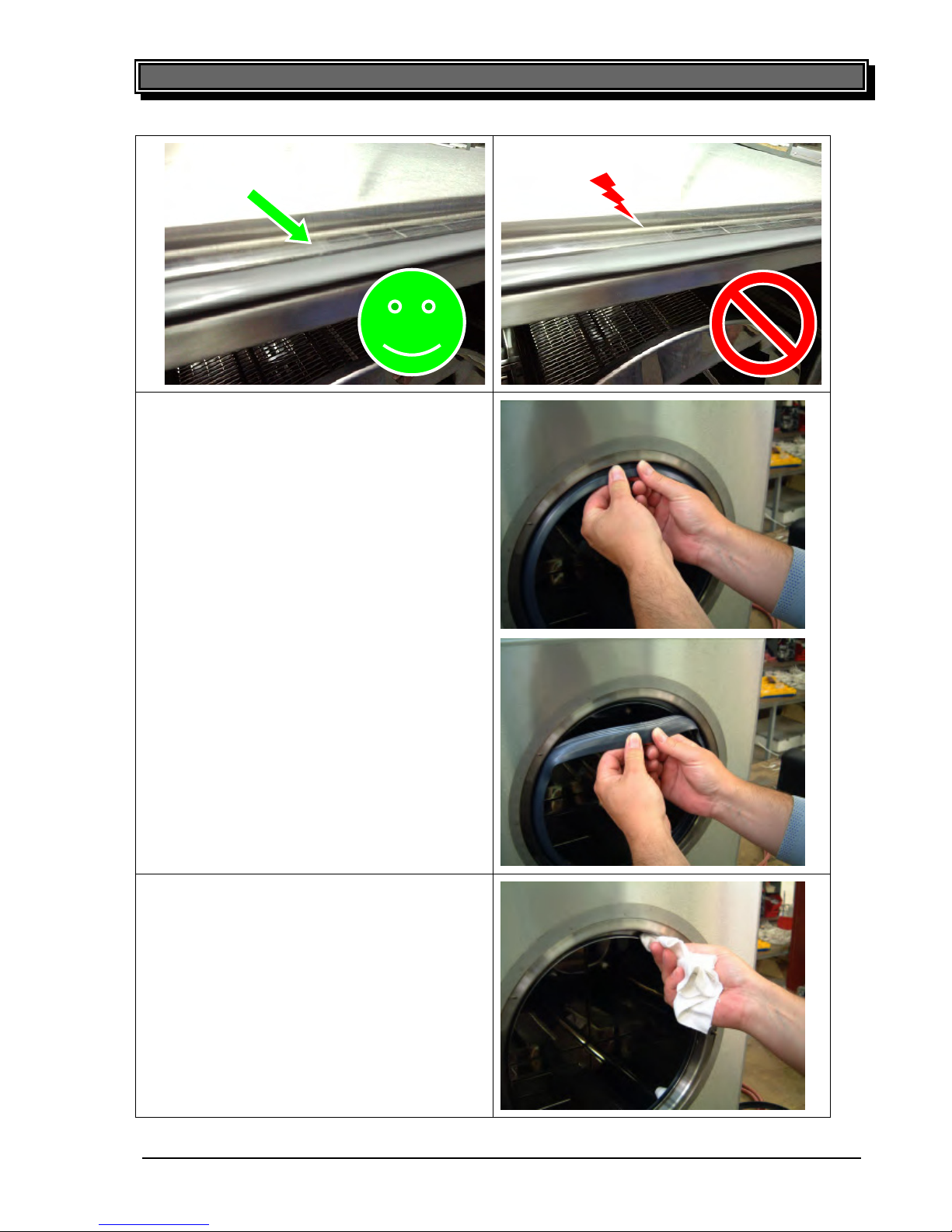
5. Finally check proper placement of the seal in
the notch!
Page 28
Error! Style not defined. 29
printed: 05/2013 Subject to change! RoFryUserManual.doc
6. Insert lamella sheet and basketholder again.
Close the door. Remove the old basket gasket by pulling it out.
7. Clean the notch of the seal; remove grease
and other residues.
30 Error! Style not defined.
printed: 05/2013 Subject to change! RoFryUserManual.doc
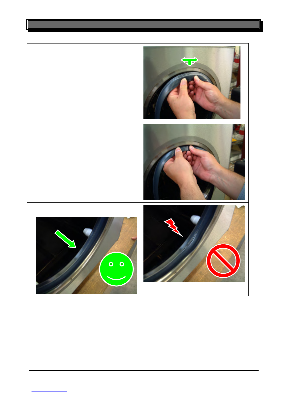
8. Put in the new seal. Place the splice of the
seal in the middle of the upper notch.
9. Push the seal into the notch. Make sure nei-
ther to stretch nor to forge the seal.
10. Finally check proper placement of the seal
in the notch!
Page 29
30 Error! Style not defined.
printed: 05/2013 Subject to change! RoFryUserManual.doc
8. Put in the new seal. Place the splice of the
seal in the middle of the upper notch.
9. Push the seal into the notch. Make sure neither to stretch nor to forge the seal.
10. Finally check proper placement of the seal
in the notch!
Page 30
Error! Style not defined. 31
printed: 05/2013 Subject to change! RoFryUserManual.doc
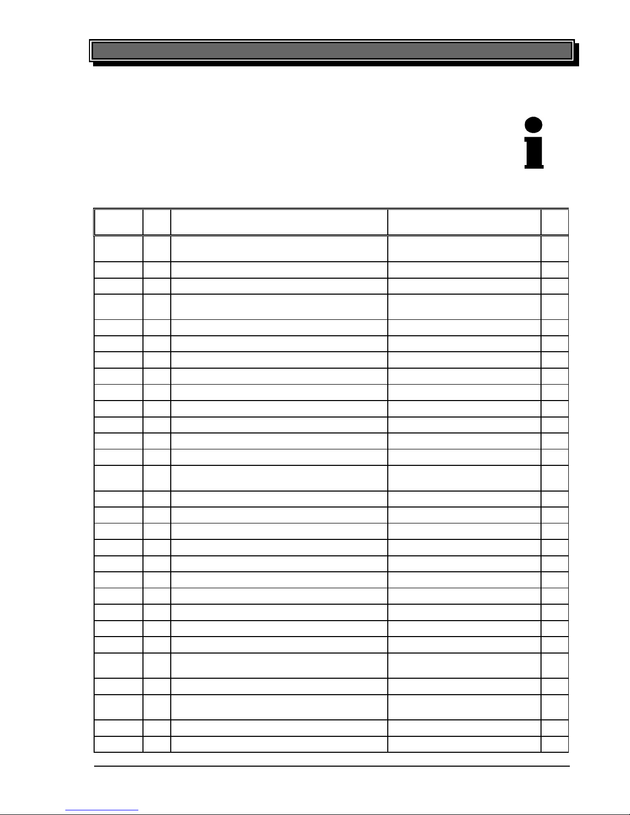
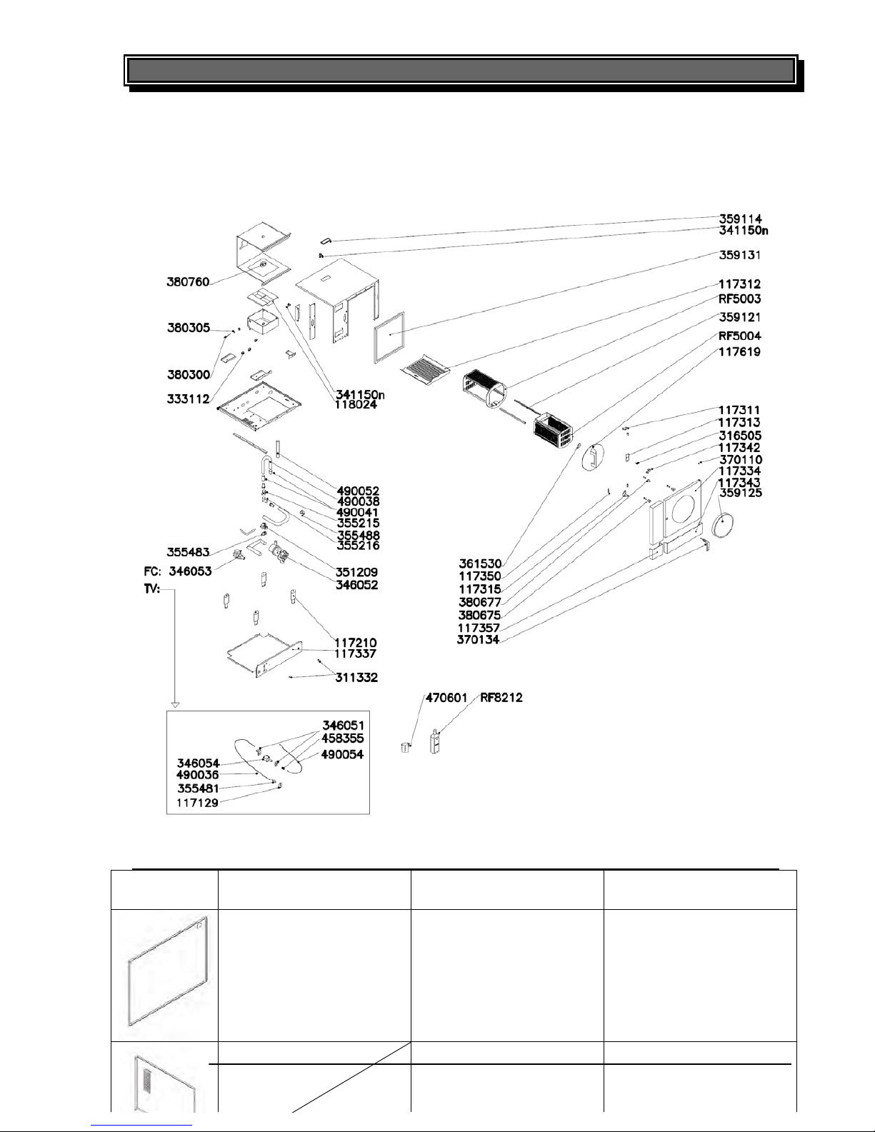
6.7 Spare Parts
Defect parts are to be replaced only by original spare parts of UBERT
GASTROTECHNIK GMBH; the replacement is to be carried out only by their service
personnel or by your authorized Serv
ice companies. If you do not observe this note or
in case of manipulation of a third party any claims for guarantee will become invalid!
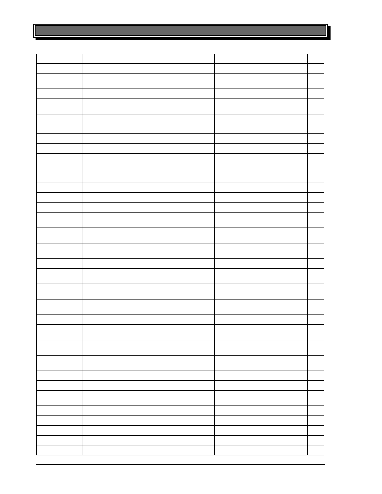
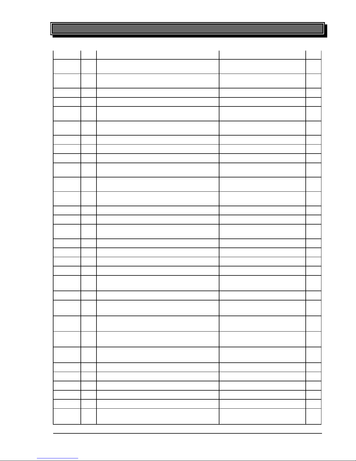
6.7.1 Spare part list
Me
nge
Bezeichnung Name VT
117051 1 Deckel Zu- und Abluftkanal Flap for air intake and exhaust
channel
117129 1 Reduzierscheibe Assembly plate
117210 4 RoFry Stellfuß Leg assy RoFry
117241 1 Gegenflansch für Heizkörper RoFry counter flance for heating ele-
ment
117311 1 Türscharnier oben RoFry Doorhinge top
117312 1 Lamellenblech Particle separator
117313 1 Montageblech Tür Servicepanel door
117315 1 Türscharnier unten RoFry Doorhinge bottom
117334 1 Tür Door
117342 1 Schalterwippe für Korberkennung RF Linkage basket switch
117343 1 Auffangwanne unter Tür Drip tray
117350 1 Lasche für Türverschluß Lock plate for door lock
117357 1 Abdeckung neben Auffangwanne Front cover bottom left
117360 1 Abschirmung Korbmotor für Nährungsschal-
ter
Heat protection for proximity
switch
117395 1 Bedienblende RF-300 Front cover RF-300
117396 2 Seitenblende RF-300 Side cover RF-300
117397 1 Rückwand RF-300 Rear cover RF-300
117403 1 Frontblende RF-330 / RF-360 Front cover RF-330 / RF360
117431 1 Bedienblende RF-330 Front cover RF-330
117432 1 Seitenblende RF-330 Side cover RF-330
117433 1 Rückwand RF-360 / RF-330 Rear cover RF-360 / RF-330
117442 1 Bedienblende RF-360 Front cover RF-360
117443 1 Seitenblende RF-360 Side cover RF-330
117619 1 Korbblende kompl RoFry Frontplate for basket
118022 1 Gegenflansch für Garraumlüfter und Korb-
motor
counter flance for fan and bas-
ketmotor
118024 1 Filtersieb kompl. Metal filter
311332 4 Flachkopfschraube mit Schlitz und Ansatz
M5*2,5*7 A2
slotted pan-head screw
M5*2,5*7 A2
316502 1 Feder, Zug 1.4310 0,63*5,0*50 mm Tension spring
316505 2 Feder, Druck, DIN 9025 verzinkt Compression spring
Page 31
32 Error! Style not defined.
printed: 05/2013 Subject to change! RoFryUserManual.doc
d=1,0*11*35 mm RoFry
333112 4 Kabel Tülle 46*32 RoFry Cable grommet 46*32
333302 4 Kabel, Porzellanklemme, 2,5mm2, 2-polig,
mit Loch
terminal block, ceramic
333305 14 Wago, Klemmblock, 10qmm Wago terminal block 10mm²
333306 2 Wago Endwinkel für TS35 Sideblock (field-/main terminal
block)
333307 5 Wago Brücken Bridge for terminal block
333308 5 Wago Abschottung Separator for terminal block
335092 1 Sicherungsklemme Fuse holder 5x20
335095 1 Feinsicherung 5x20 - 0.5 A träge fuse 5x20 - 0.5 A träge
340814 1 Drehgeber UUS1-2 Encoder for UUS01
340819 1 Summer, Miniartur 5-12V Buzzer 5-12V
340821 1 Bedienteil CPU - UUS02 RT-CC / ROFRY computer control unit UUSO2
340822 1 Leistungsteil - UUS02 RT-CC / ROFRY Powerunit for 340821 UUS02
341122 1 Induktiver Näherungsschalter Inductive proximity switch
341150 2 Microschalter - Türkontakt/Korbkontakt door switch (RHD)
341152 1 Schalter/Hauptschalter RoFry Europa Ver-
sion
Main Switch
342220 1 Microthermschalter, 60C R-20 C-279/C 370;
Schliesser
Temperature switch (freshair-
fan)
342224 1 Sicherheitstemperaturbegrenzer 300° Au-
schalttemp.
High Limit Switch 300°C
342237 1 Garraumfühler PT100 inkl. Verschraubung Temperature probe PT100
342239 1 Klemm-Verschraubung M8 mit Gegenmut-
ter für 342237u.342245
Screw joint for temperature
probe 342237&342245
342412 1 Schütz 26A 220-240V 50/60Hz Contactor 26A 220-240V
50/60Hz
343180 1 RHK RoFry Ausführung 16,335 kw heating element RoFry 15,0
kw, 230V
344115 1 Rändelmutter A2 DIN 467 M6 Knurled nut
344118 1 Querstromgebläse RoFry Radial fan with thermostat
switch
344133 1 Garraumlüfter (Heißluftgebläse) RoFry N,
UL Version
Fan (oven chamber)
346051 2 Befestigung für Frischwasserpumpe Mounting bracket for fresh
water pump
346052 1 Umwälzpumpe Typ CP50-125 Circulation Pump
346053 1 Entleerungspumpe Drain Pump
346054 1 Frischwasserpumpe / Schwingkolbenpumpe Fresh-water pump for TV-
Version
351209 1 Magnetventil RoFry Magnetic valve
355215 1 Rohrbelüfter 3/4"Fx3/4"F aerator 3/4"Fx3/4"F
355216 1 Winkelstück 90° 3/4"Mx3/4"F Pipe bend 90° 3/4"Mx3/4"F
355481 1 Kupplung, weiß Frischwasserzufuhr Clutch fresh-water-supply
355483 1 Kupplung, grau Brauchwasserabfluß Clutch waste-water-outlet
Page 32
Error! Style not defined. 33
printed: 05/2013 Subject to change! RoFryUserManual.doc
355488 1 Stecker mit Winkelschlauchtülle Plug waste-water-outlet, angle
359114 345
mm
Dichtung für Luftkanal am Gehäuse seal for air conduit
359117 1 Flachdichtung für Zu -
Abluftklappe schwarz,
Silikon, geschäumt
gasket (intake/ exhaust) X
359118 1 Wellendichtung PTFE 22*35*7 ohne O-Ring Shaft seal PTFE X
359120 1 V-Ring, Viton V-Ring X
359121 2 Gleitschienen Korbführung PTFE/Glas Sliding rails (basket)
PTFE/Glass
X
359123 1 Dichtung für ROFRY Heizkörperflansch gasket RoFry heating element
flange
359125 1 Korbdichtung als Ring verklebt 920mm lang gasket (basket) L = 920 mm X
359126 2 Carbondichtung Carbon seal for main fan X
359128 1 Wellendichtung BA-PTFE 20*35*7 Shaft seal PTFE X
359131 1 Garraumdichtung eckig RoFry Door gasket with sharp cor-
ners RoFry
X
361301 1 Knebel, ohne Referenzpunkt RT507 /
RT505
knob without reference point
361303 1 Deckel mit Fingermulde für Knebel
RT507/RT505
cab with finger basin
361530 1 Führungsbuchse für Korbblende ROFRY Bearing for Basket front-shield X
370110 1 Abdeckkappen für Muttern M6 schwarz covering cap
370134 1 RoFry Türgriff, Dreh-Spann-Verschluß Door lock, compression for
RoFry
380104 1 Motor Korbantrieb Motor basketdrive
380123 1 Klappenstellmotor Flap motor
380300 1 Elektrode für Niveauregulierung Electrode for Level control
380305 2 Dichtung Cu (Kupfer) DIN 7603 Seal copper
380607 1 Lager Flansch mit Einsatz Hochtempe-
ratur
Bearing for use with motor
basketdrive 380104
380615 1 Flansch für Lüftermotor ROFRY Flange for fan motor
380675 2 Gleitauflage Korbhalter mit Kragen Basketholder bearingroll
RoFry with collar
380676 4 Abstandsbolzen Edelstahl, für Lüftermo-
tor RoFry
Bolt for fan-motor
380677 1 Gleitauflage Korbhalter ohne Kragen Basketholder bearingroll
RoFry without collar
380760 1 Verteilerteller water spray system apertu-
re
419001 1 Scheibe Dekor RoFry Decor panel glass RoFry
419012 1 Bedienpaneel Scheibe RoFry Operator panel glass RoFry
458355 1 Schlauchtülle 1^/8"x1/8" 1845 Ms bk Hose nozzle
470601 1 Messbecher ROFRY, 200 ml dosing cup
490036 1 Schlauch Silikon transp. gem. FDA Silicone-hose transparent
490038 1 Schlauch mit integrierten Endstücken
Ø19mm (Innen)
Hose incl. end fittings
34 Error! Style not defined.
printed: 05/2013 Subject to change! RoFryUserManual.doc
490041 1 Endstück für Schlauch 21mm
End fitting for hose
490052
1
Form-Schlauch 35*4,5 (Innen Ø * Wan-
dung)
Tube 90° angled
490054 1 Schlauch Silikon transparent
Silicon tube transparent
RF5003 1 Korbhalter kompl. für RoFry
Basketholder assy RoFry
RF5004 1 Korb kompl RoFry
Basket assy RoFry
RF8212
1
RoFry Dosierflasche 1Liter (ohne Inhalt)
für Entkalker M
RoFry Lime Remover M
dose-bottle 1liter (empty)
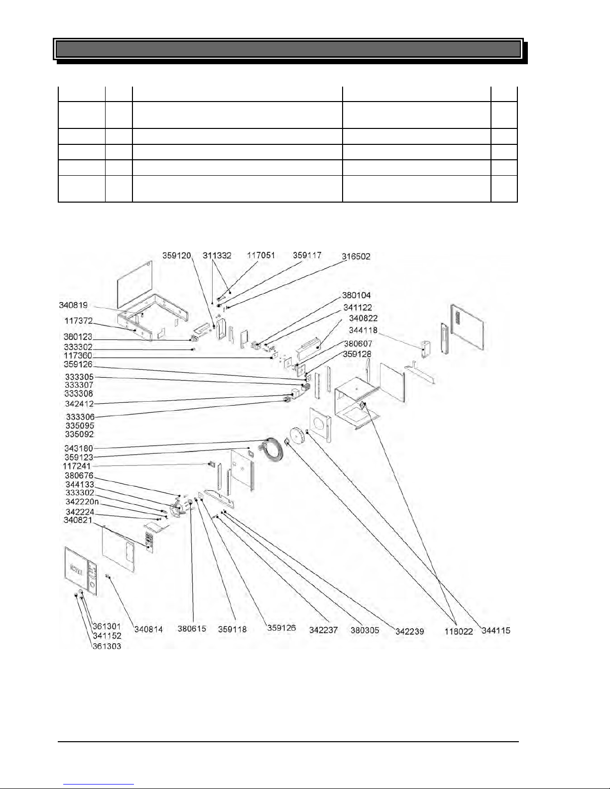
6.7.2 Exploded view
Page 33
34 Error! Style not defined.
printed: 05/2013 Subject to change! RoFryUserManual.doc
490041 1 Endstück für Schlauch 21mm End fitting for hose
490052 1 Form-Schlauch 35*4,5 (Innen Ø * Wan-
dung)
Tube 90° angled
490054 1 Schlauch Silikon transparent Silicon tube transparent
RF5003 1 Korbhalter kompl. für RoFry Basketholder assy RoFry
RF5004 1 Korb kompl RoFry Basket assy RoFry
RF8212 1 RoFry Dosierflasche 1Liter (ohne Inhalt)
für Entkalker M
RoFry Lime Remover M
dose-bottle 1liter (empty)
6.7.2 Exploded view
Page 34
Error! Style not defined. 35
printed: 05/2013 Subject to change! RoFryUserManual.doc
RF-300 RF-330 RF-360
117397
Rückwand RF-300
Rear cover RF-300
117433
Rückwand RF-360 / RF-
330
Rear cover RF-360 / RF-
330
117433
Rückwand RF-360 / RF-
330
Rear cover RF-360 / RF-
330
117432
Seitenblende RF-330
Side cover RF-330
117443
Seitenblende RF-360
Side cover RF-330
36 Error! Style not defined.
printed: 05/2013 Subject to change! RoFryUserManual.doc
6.8 Accessories
The following accessories are available on request:
• Spare basketholder, complete Part. No.: RF 5003
• Spare basket, complete Part. No.: RF 5004
• RoFry
®
-cleaner Part. No.: RF 8200
25kg-Container
• RoFry
®
-lime remover Part. No.: RF 8210
5l-Canister
• Refill basket Part. No.: RF 5010
• Scoop Part. No.: RF 5011
• French-fries-portioner Part. No.: RF 5012
• French-fries-bag rest Part. No.: RF 5013
• Store shelf Part. No.: RF 5015
• RoFry
®
-warming basin 230V / 2,0kW / 50-60Hz / 1Ph/ N Part. No.: RF 7100
• Intermediate shelf for warming basin Part. No.: RF 7110
• RoFry
®
-protection gloves Part. No.: RF 8015
Accessories for standard version RF-###-ST:
• RoFry
®
-spray Art. Nr: RF 8000
• RoFry
®
-KOTE-sprayer Art. Nr: RF 8010
• Soaking tank 230V / 2,0kW / 50/60Hz / 1Ph/ N Art. Nr: RF 8030
• Soda 24kg-unit Art. Nr: RF 8045
Page 35

36 Error! Style not defined.
printed: 05/2013 Subject to change! RoFryUserManual.doc
6.8 Accessories
The following accessories are available on request:
• Spare basketholder, complete Part. No.: RF 5003
• Spare basket, complete Part. No.: RF 5004
• RoFry
®
-cleaner Part. No.: RF 8200
25kg-Container
• RoFry
®
-lime remover Part. No.: RF 8210
5l-Canister
• Refill basket Part. No.: RF 5010
• Scoop Part. No.: RF 5011
• French-fries-portioner Part. No.: RF 5012
• French-fries-bag rest Part. No.: RF 5013
• Store shelf Part. No.: RF 5015
• RoFry
®
-warming basin 230V / 2,0kW / 50-60Hz / 1Ph/ N Part. No.: RF 7100
• Intermediate shelf for warming basin Part. No.: RF 7110
• RoFry
®
-protection gloves Part. No.: RF 8015
Accessories for standard version RF-###-ST:
• RoFry
®
-spray Art. Nr: RF 8000
• RoFry
®
-KOTE-sprayer Art. Nr: RF 8010
• Soaking tank 230V / 2,0kW / 50/60Hz / 1Ph/ N Art. Nr: RF 8030
• Soda 24kg-unit Art. Nr: RF 8045
Page 36

Copyright Information
Copyright © 2013 Brice Australia Pty. Ltd.
This document may not be reproduced, in whole or in part, by any means without the prior express written permission of the copyright
owner.
Brice and the BRICE logotype are trademarks of Brice Australia Pty. Ltd.
Printed in Australia
BA179 Fornochef 5/13
 Loading...