

Page 1
Installation & Operation Manual
Important Information ............................................2
Safety Information .................................................3
Component Identication ......................................3
Specications ........................................................4
Electrical Requirements ........................................4
Document # 101522 0608 REV A ER 784
Installation .............................................................5
Operation ..............................................................8
Table Adjustments ............................................... 11
Maintenance ........................................................19
Limited Warranty .................................................19
Page 2
IMPORTANT INFORMATION
General
The AssistPRO is designed to provide positioning and
support of patients during general examinations con-
ducted by qualied medical professionals. Read and
understand all operating instructions, safety information,
and maintenance requirements contained in this manual
prior to operating the table. Become familiar with all of
the table functions before using it with a patient.
The AssistPRO is primarily used in examination rooms
for general examinations and minor procedures. The
wide variety of positions, adjustable legrest, adjustable
headrest, stirrups, and treatment pan, create a safe and
convenient patient positioning table.
Controlled via the hand pendant or foot control, four powered motions easily adjust the table into a wide variety
of positions. The table ascends to 40” high, and can be
lowered to 19” (thereby providing easier wheelchair transfer). The seating surface can be tilted from a horizontal
position to an angled position of up to 30º. The backrest
can be adjusted from a at position to an 85º angle for
seating. Finally, the legrest can be adjusted from a vertical position for seating, to a horizontal position for laying.
Remember to read through the entire manual. The fea-
tures briey mentioned are just an introduction into the
capabilities provided by the AssistPro. This table was spe-
cically engineered to be the most accessible and safest
table on the market. Multi-density upholstery, push-only
actuators, and numerous on/off switches are just a few
of the many touches that make the AssistPRO the best
procedure table for every ofce.
Service
If you require assistance with the installation or operation of your
AssistPRO,
1-800-558-8777. Our trained staff will assist you in attempting to
correct the problem directly over the phone. If service is required,
a factory authorized technician will be sent to your location.
Please ll in the following information for use when calling the
Brewer Company or your distributor with questions regarding
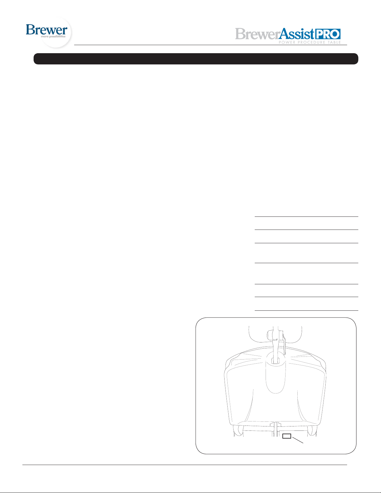
your unit. See Figure 1 for model and serial number location.
Date of Purchase
Serial Number
Model Number
call the Brewer Customer Service Department at
The AssistPRO is also capable of storing four preferred
positions ino the tables memory. Utilizing an intuitive two
step programming method, the user can recall any programmed position with the touch of a button. See page 14
for complete programming instructions.
In addition to the electronically controlled positions noted
above, several manual adjustments are available:
1. The legrest can be manually adjusted from a sitting to
a kneeling position.
2. With the table in the horizontal position, the legrest
can be extended an additional 5” for tall patients.
3. Stirrups may be manually extended and positioned
anywhere within the lateral range of travel.
4. A removable treatment pan is housed underneath the
front of the seat for easy access. Simply pull the tray
out for use during examinations.
5. A three point pivot system allows the user to adjust
the angle and position of the headrest.
6. The backrest incorporates a self-storing paper roll.
Authorized
Dealer Name
Dealer
Phone Number
Dealer Address
The table is designed to accommodate a maximum
patient weight of 450 lbs.
Document # 101522 0608 REV A ER 784 2
Model &
Serial Number
Figure 1. Model and Serial Number Location
Page 3
SAFETY INFORMATION
Safety Information
The primary concern of The Brewer Company is that the
equipment is operated and maintained with the safety of
the patient and healthcare staff in mind. To ensure safe
and reliable operation:
• Read and understand all instructions in this manual
before attempting to install or operate the unit.
• Ensure that appropriate personnel are informed on
the manual contents. This is the responsibility of the
purchaser.
• Ensure that this manual is located near the table, or if
possible permanently afxed to the table.
COMPONENT IDENTIFICATION
Failure to follow instructions with this symbol
could result in serious personal injury and/or damage
to the unit.
DANGER indicates an imminently hazardous
situation which, if not avoided, will result in death
or serious injury.
WARNING indicates a potentially hazardous
situation which, if not avoided, could result in death
or serous injury.
CAUTION indicates an imminently or poten-
tial hazardous situation which, if not avoided, may
result in serious injury and/or equipment damage.
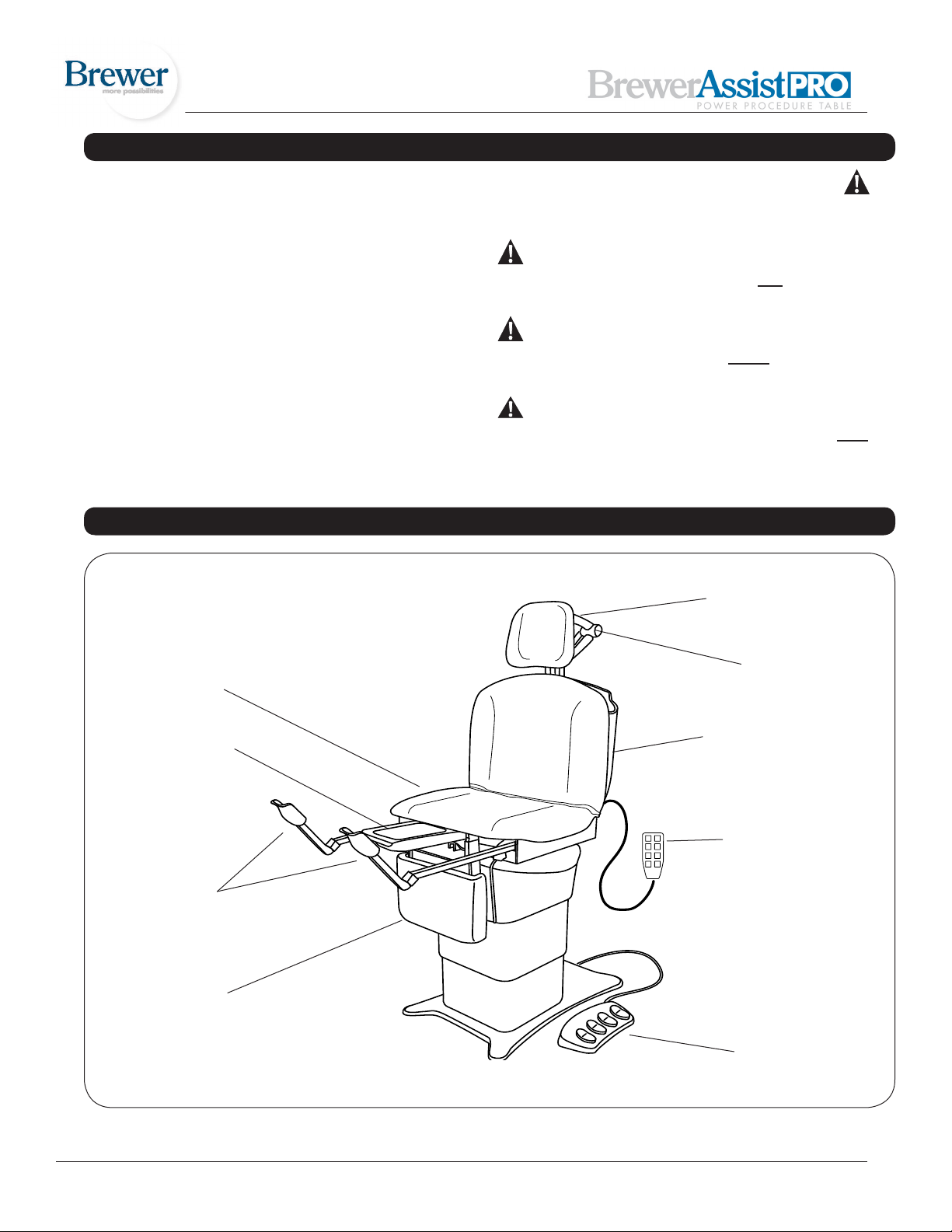
Headrest (adjustable)
Seat
(adjustable angle)
Treatment
Pan
Stirrups
Leg Section
(adjustable angle)
Headrest Linkage
Assembly
Backrest
(adjustable angle)
Programmable
Hand Pendant
Programmable
Foot Control
Figure 2. Component Overview
Document # 101522 0608 REV A ER 784 3
Page 4
SPECIFICATIONS
Weight of Table .....................................................550 lbs.
Load Rating (maximum):
Seat/Back .............................................................450 lbs.
Legrest (Flat & Kneeling) ......................................450 lbs.
Headrest ...............................................................100 lbs.
Back Section Range ............... 0° (horizontal) to +85° ± 5°
Table Top Height Range ...........19 ± 0.5 in. to 40 ± 1.0 in.
Leg Section Range ............0° (horizontal) to 90° (vertical)
Table Top
Tilt Range ................ 0° (horizontal) to +30° ± 5° (foot up)
Dimensions:
Upholstered Headrest..................13 in. wide x 11 in. high
Upholstered Top ....................28.0 in. wide x 44.5 in. long
Upholstered
Leg Rest ....…………………16.5 in. wide x 11.25 in. high
Overall Length ..................................................69 in. long
With Headrest/
Footrest Extended ............................................90 in. long
Electrical Requirements
..................115 VAC nominal, 60 HZ, 5.8 amps maximum
Duty Cycle (10%)
................. 2 minutes on / 18 minutes off (motor run time)
Power Cord.......................................................................
............ Extends 70 in. (Minimum) from table. 18 AWG / 3
............. conductor, SJT grey jacketed junior hard service
............with hospital plug
Type of protection against electrical shock …….. Class 1
.......................................................................... Grounded
Type of protection
against electrical shock …….. .................. B applied parts
Type of protection against ingress of water……. Ordinary
Type of protection against ingress of water for foot control..IPX1
Can accept paper rolls of
....................................................................18 in. x 3.0 in.
....................................................................21 in. x 3.0 in.
Certications* .................................UL6060-1; UL2601-1;
..........................IEC60601-1; CAN-CSA C22.2 No. 601.1
Transport and Storage Conditions:
Temperature Range......................................-20º to 150º F
Relative Humidity...........................................10% to 90%
Operating Conditions:
Temperature Range ........................................ 65° to 85°F
Relative Humidity...........................................10% to 90%
ELECTRICAL REQUIREMENTS
WARNING
When performing a cauterization or similar treatment, the patient must be insulated from the metal
portions of the table by nonconductive material.
Failure to do so may result in electrical shock or
burns to the patient.
WARNING
Use 115 VAC, 60 Hz alternating current only. Failure
to do so may result in electrical shock to personnel
and will result in damage to the table.
WARNING
Do not use this table in an explosive or oxygenenriched atmosphere. Failure to do so may result
in serious personnel injury or death.
* ETL classied in the United States and Canada
per the following standards.
CAUTION
Do not use any power supply other than that
listed on the rating label (Figure 1). Failure to do
so may result in serious injury and/or equipment
damage.
CAUTION
This product has been evaluated with respect to
electrical shock, re, and mechanical hazards only
in accordance with UL60601-1; IEC60601-1;
UL2601-1; CAN/CSA C22.2 No. 601.1
Document # 101522 0608 REV A ER 784 4
Page 5
INSTALLATION
Overview
Perform the following sequence in order when setting up
the table:
- Uncrating
- Leveling the Base
- Installing the Foot Control & Hand Pendant
Uncrating
NOTE: Inspect all boxes and contents for damage. Report any damage to the carrier immediately.
CAUTION
To avoid damaging the table’s upholstery or painted surfaces, DO NOT use a knife or other sharp
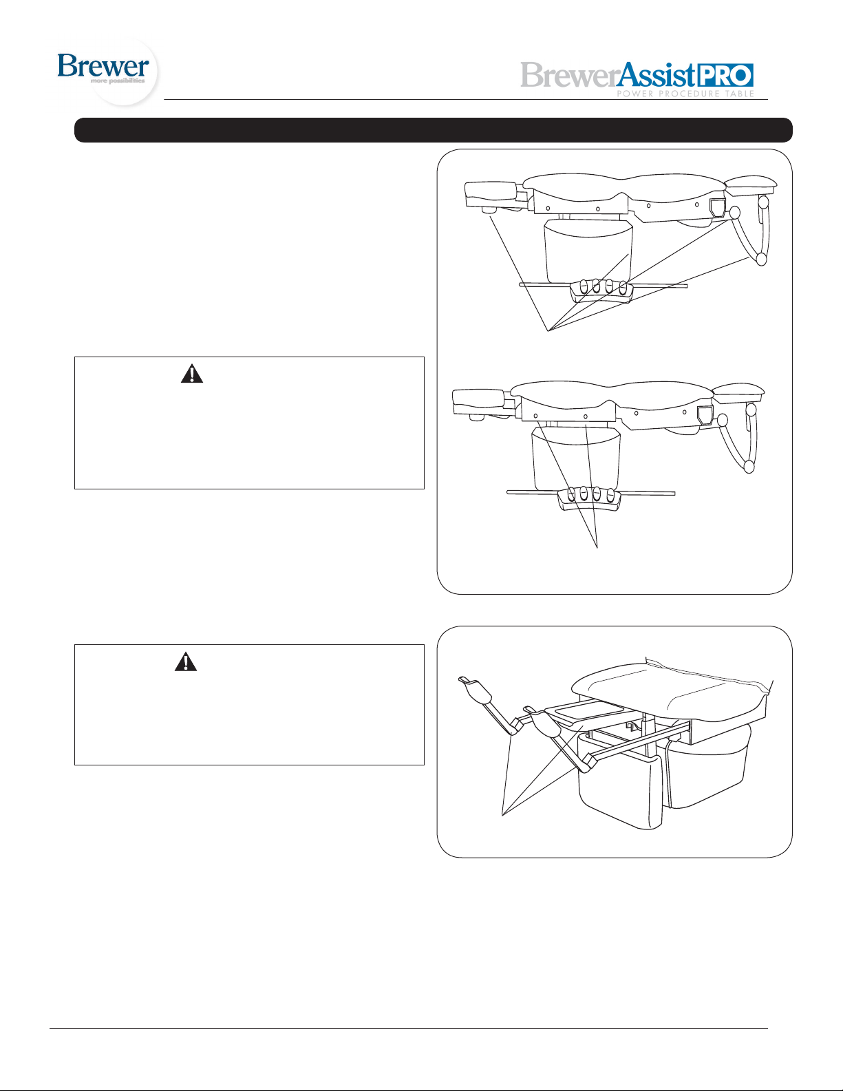
object to open the packaging. Also, to avoid damaging the table lift only at points indicated in Figure
3. Do not lift at other points as indicated in Figures
3 and 4.
1. Using a 1/2” open-end wrench, or socket, unbolt the
table from the wooden shipping skid by removing the
four bolts located underneath the table’s base; two on
each side.
2. Remove the table from the shipping skid by sliding it
off the front of the skid. Be sure to lift at the correct
points as indicated in Figure 3. Position the table in
the desired room location.
DO NOT lift at these points!
Lift table at these points
Figure 3. Table Lift Points
WARNING
The table weighs approximately 550 lbs. Two or
more people should assist in removing the table
from the shipping skid. Also, use proper lifting
techniques when lifting. Failure to do so could
result in serious injury.
3. Remove packing tape from stirrups (Figure 4). Pull
out treatment pan slide and remove packing tape
from the treatment pan assembly components. Return treatment pan slide to its stowed position.
4. The electrical rating for this unit is 115 VAC, 60 Hz,
5.8 amps. The three-pronged grounding plug on the
table power cord must be plugged into a matching
three-pronged, grounded, non-isolated, correctly
polarized 115 VAC receptacle.
Document # 101522 0608 REV A ER 784 5
Do Not Lift
Figure 4. Stirrups and Treatment Pan
Page 6
INSTALLATION (CONTINUED)
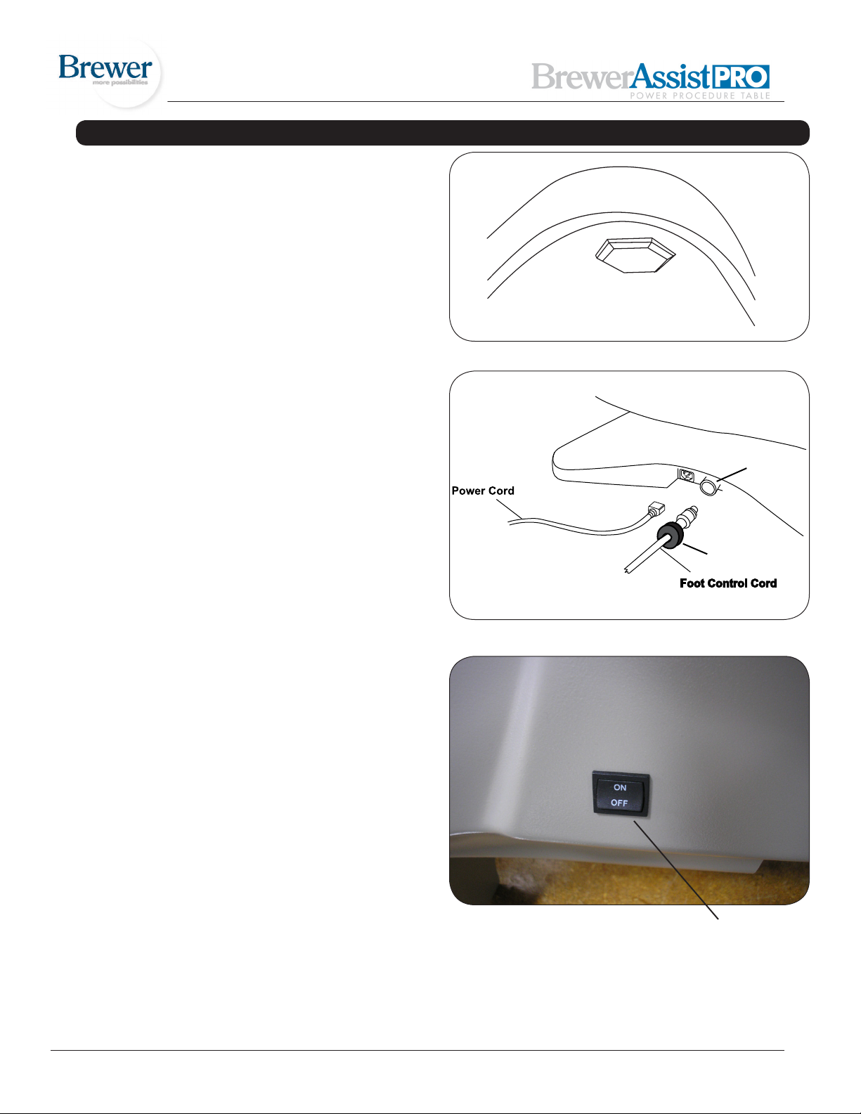
Locking Collar
Receptacle
Leveling the Table
A leveling screw pad (Figure 5) is located in six places
under the table’s base. Adjust the six leveling pads to
achieve a solid, level installation.
Installing the Power Cord
1. Remove the power cord from the shipping box.
2. Insert the plug end of the power cord into the receptacle on the table (Figure 6). Make sure the plug end
shape is correctly oriented to the receptacle shape.
Installing the Foot Control
1. Remove the foot control from the shipping box.
Figure 5. Leveling Screw Pad (located under table)
2. Insert the end of the cord into the foot control receptacle on the table (Figure 6). Make sure the tab on the
cord plug is aligned with the groove in the receptacle,
and the plug is fully seated.
3. Thread the locking collar onto the receptacle
4. Make sure the on/off switch located on the backrest
shroud is turned to the “on” position. See gure 7.
5. Make sure both Safety On/Off Switches are on (lighted).
See gure 9.
6. Test the foot control for operation.
Figure 6. Power Cord & Foot Control Cord Receptacles
Figure 7
Foot Control/Hand
Pendant On/Off
switch
Document # 101522 0608 REV A ER 784 6
Page 7
INSTALLATION (CONTINUED)
Installing the Hand Pendant
1. Remove the hand pendant from the shipping bag
2. Insert the plug end of the cord into the hand pendant
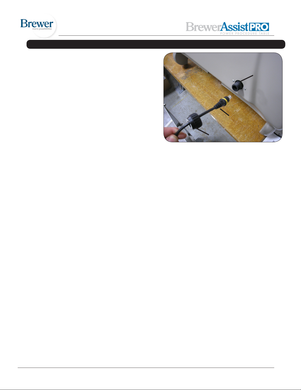
receptacle on the backrest shroud. See gure 8.
3. Make sure the tab on the cord plug is aligned with the
groove in the receptacle and plug is fully seated
Receptacle
4. Thread the locking collar onto the receptacle
5. Test the hand pendant for operation
Hand
Pendant
Cord
Locking
Collar
Figure 8
Document # 101522 0608 REV A ER 784 7
Page 8
OPERATION
General
WARNING
If the table malfunctions, immediately remove your
hand or foot from the controls, unplug the power
cord from the electrical receptacle, and assist the
patient from the table. If table continues to malfunction, call for service. Do not attempt to repair
table yourself.
WARNING
Before initiating power, keep personnel and equipment clear of the table movement to avoid personal
injury or equipment damage.
NOTE: For optimum table performance, allow the table to
reach room temperature before operating.
NOTE: The table is not designed for continuous operation. If the table is operated continuously causing the
control to exceed its allowable operating temperature, the
table will go into a reduced speed mode. If normal operation ceases, do not attempt to operate the table. Allow the
table to cool for 10-15 minutes before attempting to use
again.
NOTE: If operation does not resume after a cooling
period of one hour, contact your dealer or an authorized
service center for repair.
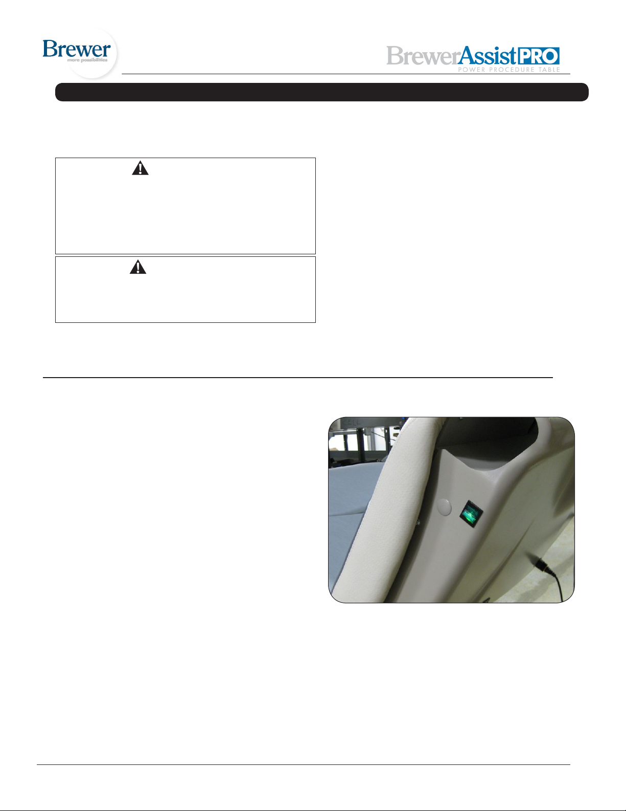
Safety On/Off switches
1. The table is equipped with two On/Off switches that disrupt the main power to the table.
2. The switches are located on the upper left and right hand
sides of the backrest shroud. See gure 9.
3. In the “On” position the switch is lighted green.
Both switches must be in the On, lighted position for the
table to operate.
Figure 9
Document # 101522 0608 REV A ER 784 8
Page 9
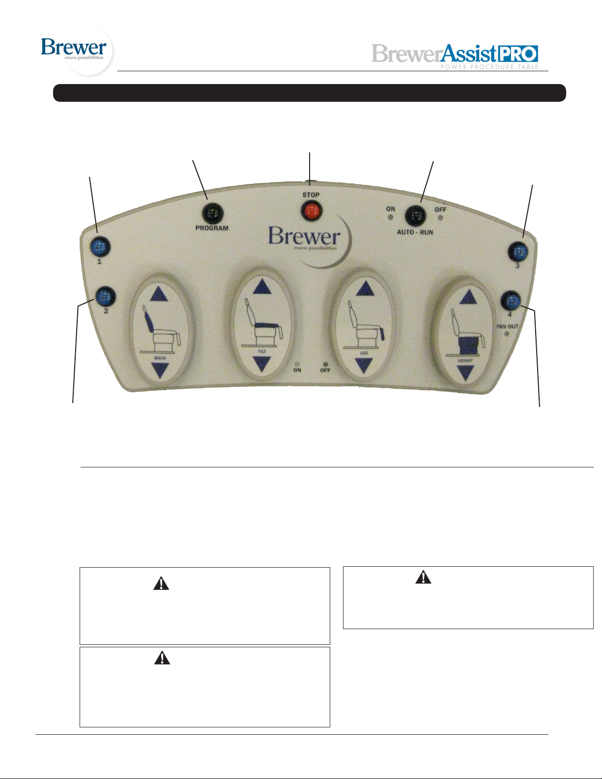
OPERATION (CONTINUED)
Program
Recall #1
Program
Recall #2
Back
Up
Back
Down
Program
Set
Tilt
Up
Tilt
Down
Stop
Leg
Up
Leg
Down
Program Recall
Mode
Table
Up
Table
Down
Program
Recall #3
Program
Recall #4
Figure 10
Controls
1. See gure 10 for the pedal and button identications on
the foot control
2. See gure 11 for the button identications on the hand
pendant
CAUTION
The foot control and hand pendant are moisture
resistant and run on low voltage. To avoid temporary or permanent damage to the controls, do not
immerse in water or liquids.
CAUTION
Keep foreign objects away from controls. To avoid
accidental operation, be sure the controls are NOT
positioned below the legrest or headrest linkage.
Failure to do so could result in unwanted motion
and possible damage to the table.
WARNING
Keep personnel and equipment clear of table before initiating movement to avoid personal injury
or damage to the equipment.
NOTE: Each control function will automatically stop moving when either the UP or DOWN travel limit is reached.
If the button is pressed with travel at its limit, the actuator will not run. Sensors prevent the actuator motor from
operating when travel limit has been reached, preventing
wear of the actuator.
Document # 101522 0608 REV A ER 784 9
Page 10
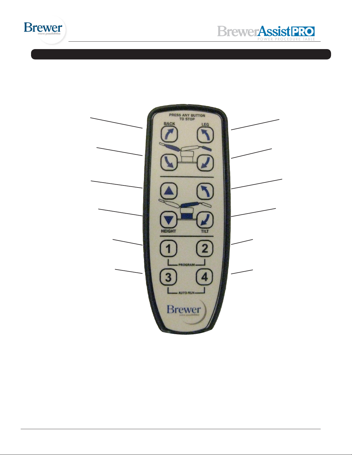
OPERATION (CONTINUED)
Back Up
Back Down
Table Up
Table Down
Program Recall #1
Program Recall #3
Leg Up
Leg Down
TiltUp
Tilt Down
Program Recall #2
Program Recall #4
Document # 101522 0608 REV A ER 784 10
Figure 11
Page 11
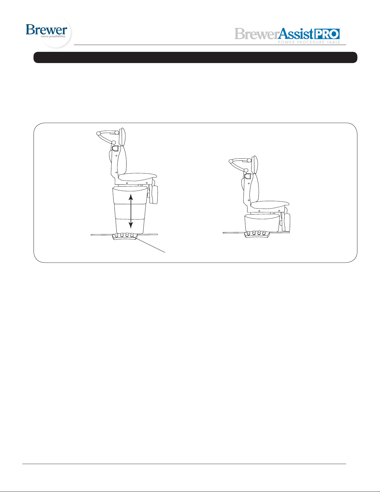
TABLE ADJUSTMENTS
Table Height (Figure 12)
The table top can be adjusted to any height between 19”
to 40”.
1. To raise the table, depress and hold the Table/Up
function until the desired height is achieved.
2. To lower the table, depress and hold the Table/Down
function until the desired height is achieved.
Table Height Control
Figure 12. Table Height Positioning
Document # 101522 0608 REV A ER 784 11
Page 12
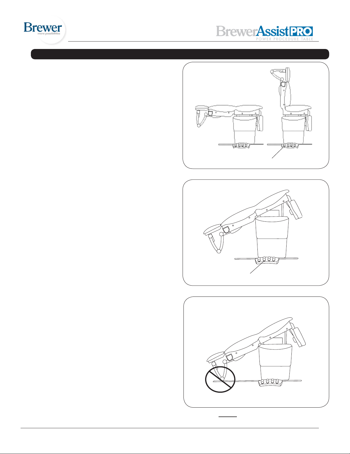
TABLE ADJUSTMENTS (CONTINUED)
Back Positions (Figure 13)
The back can be adjusted to any angle between horizontal and 85°.
1. To adjust the back from a chair (upright) position to a
horizontal position, depress and hold the Back/Down
function until the desired angle is achieved.
2. To adjust the backrest from a horizontal position to a
chair (upright) position, depress and hold the Back/Up
function until the desired angle is achieved.
NOTE: The back is controlled by an actuator that raises
the back when activated. When lowered, the actuator
retracts and gravity causes the back to lower.
Tilt Function (Figure 14)
The table top can be tilted to any angle between
horizontal and +30° (foot end of table raised).
1. To tilt the foot end of the table upward, depress and
hold the Tilt/Up function until the desired angle is
achieved.
Backrest Position Control
Figure 13. Adjusting Backrest
2. To tilt the foot end of the table downward, depress
and hold the Tilt/Down function until the desired angle
is achieved.
NOTE: The headrest linkage may contact the oor or other
object when the table is tilted (Figure 15). If this occurs,
raise the table, reduce the amount of tilt, or raise the back.
Tilt Function Control
Figure 14. Tilt Function
Document # 101522 0608 REV A ER 784 12
Figure 15. Do Not Allow Headrest to Contact Objects
Page 13
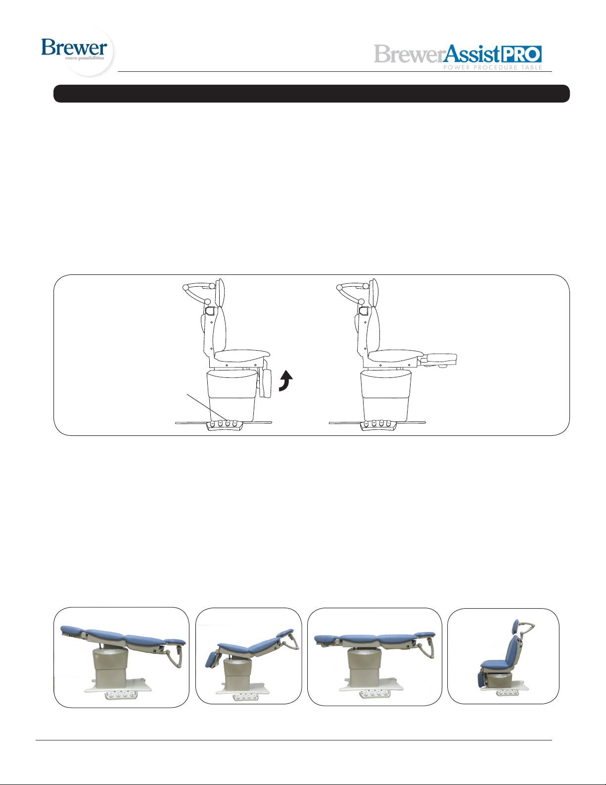
TABLE ADJUSTMENTS (CONTINUED)
Legrest Positions (Figure 16)
The legrest can be adjusted from a horizontal position to
a vertical position.
1. To adjust the legrest from a vertical position to a
horizontal position, depress and hold the Legrest/Up
function until the desired angle is achieved.
2. To adjust the legrest from a horizontal position to a
vertical position, depress and hold the Legrest/Down
function until the desired angle is achieved.
NOTE: A safety switch inhibits upward movement of the
legrest when the treatment pan tray is extend-
Legrest Position Control
ed preventing the legrest from contacting the treatment
pan tray. If the legrest is inoperable, check to ensure
that the treatment pan tray is in its fully stowed position
(inward). *When the treatment pan tray is extended, a
light on the foot control labeled “Pan Out” is illuminated.
The legrest will not rise. Depressing the legrest up function will cause the light to blink and a double beep alarm
to sound.
NOTE: The legrest mechanism is controlled by an
actuator that raises the legrest when activated. When
lowered, the actuator retracts and gravity causes the
legrest to lower.
Figure 16. Legrest Positions
Using the Program Feature
1. The table can be programmed using the hand pendant or the foot control. Up to four different positions
can be programmed.
2. The table is already programmed from the factory with
four preset positions. See gure 17 below.
3. Refer to gure 10. The mode in which the pre-pro-
grammed positions are recalled can be set by the
end user. The black “Program Recall Mode” button is
used to set the recall motion to “Auto Run” or “Con-
Position 1 Position 2 Position 3 Position 4
Figure 17
tinuous Touch”. In the “Auto Run” mode, a single
instantaneous touch of a blue Program Recall
button will recall that position. In the “Continuous
Touch” mode, the blue Program Recall button must
be held down continuously until the table reaches
the programmed position.
4. To set the program mode, depress the black “Program Recall Mode” button on the foot control for (5)
ve seconds, until (2) beeps are heard. A light
(Continued...)
Document # 101522 0608 REV A ER 784 13
Page 14

TABLE ADJUSTMENTS (CONTINUED)
on the foot control will indicate if the “Auto-Run” mode
is on or off. To set the program mode using the hand
pendant, simultaneously depress the program recall
number “3” and number “4” buttons for ve seconds
until two beeps are heard.
Programming the Table with the
Foot Control
1. Using the foot control pedals, move the table to the
desired position. (see gure 10) Tap the black “Program Set” button. The four blue “Program Recall”
buttons will ash. Tap one of the blue buttons to store
the position. The blue light will stay lit for that position
and two beeps will sound.
Note: The blue lights will ash for three seconds, after
which the program set mode is discontinued.
2. Move the table to a new position and repeat step 1 to
store up to three additional positions.
3. Any of the four stored positions can be re-pro
grammed by following the steps above.
Note: if the treatment pan tray is out, the position
recall will not work if the pre-set position requires the
legrest to move upward.
5. When the table is moving in the auto run mode, motion
of the table can be stopped by:
a. Tapping the “Stop” button on the foot control.
b. Tapping any pedal or button on the foot control.
c. Depressing any button on the hand pendant
Note: For emergency situations, the table can be turned
off using either of the two lighted switches located
at the top of the backrest. See gure 9.
Programming the Table with the
Hand Pendant
1. Move the table to the desired position. Simultaneously depress the number “1” and the number “2” “Pro-
gram Recall” buttons. (see gure 11) Release the two
buttons. Depress one of the four “Program Recall”
buttons to store the position. Two beeps will sound.
Note: The Program Set Mode will remain active for
three seconds after simultaneously depressing the
number “1” and the number “2” “Program Recall” buttons.
2. Move the table to a new position and repeat step 1 to
store up to three additional positions.
3. Any of the four stored positions can be re-pro
grammed by following the steps above.
Note: if the treatment pan tray is out, the position
recall will not work if the pre-set position requires the
legrest to move upward.
Safety
The table has a built in safety feature which helps avoid injury to the patient or physician when recalling a pro-
grammed position in the “Auto-Run” mode:
1. The table will stop moving downward once the legrest (in the stowed position) reaches a height of four inches
off the ground
2. The legrest will stop one inch from the lift column shrouding.
3. The pelvic tilt will stop after moving to 10 degrees
Document # 101522 0608 REV A ER 784 14
Page 15
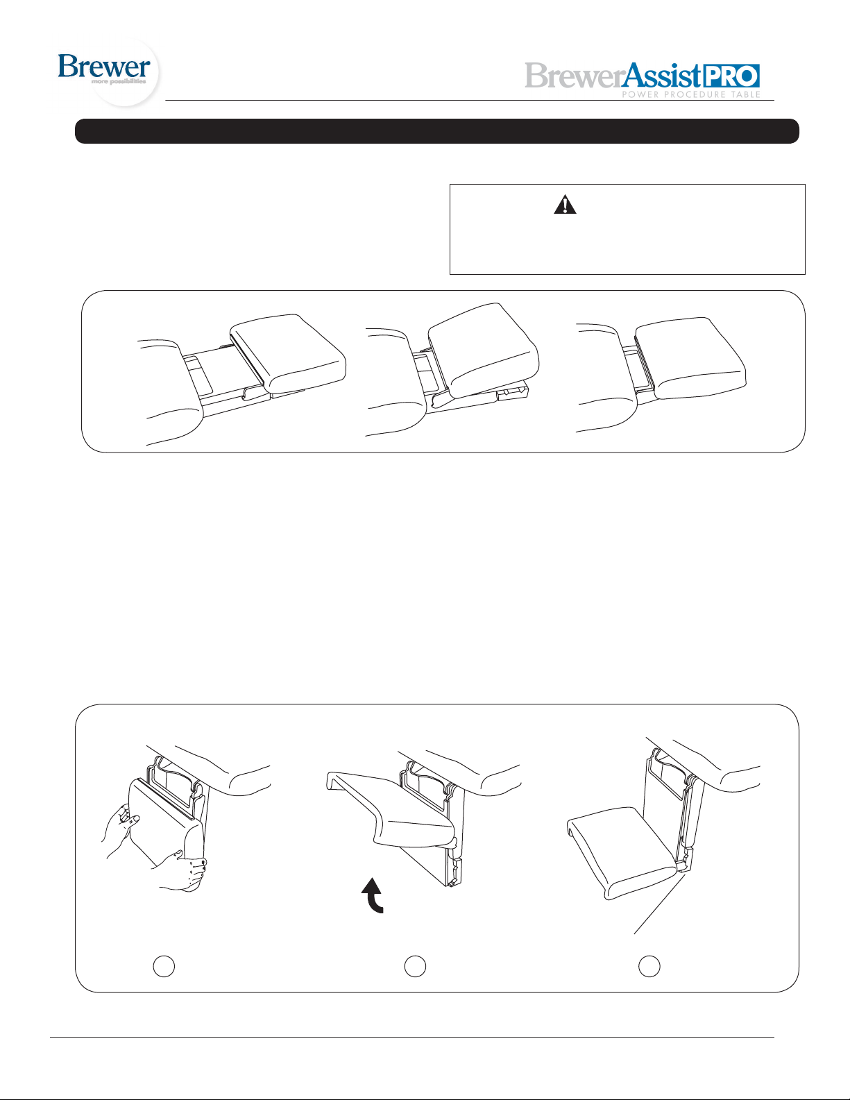
TABLE ADJUSTMENTS (CONTINUED)
Legrest Extension (Figure 18)
In the horizontal position, the legrest can be extended 5”
to increase the overall length of the table.
Lift up on the legrest and pull outward to extend the
legrest. To return the legrest to the shortest position, lift
up on the legrest and push fully inward.
Figure 18. Legrest Extension
CAUTION
To prevent damage to the unit, the legrest must be
returned to the shortest position prior to lowering
the legrest to the vertical position.
Legrest Kneeling Position (Figure 19)
The legrest can be rotated to a kneeling position.
1. Grasp the legrest cushion on both sides.
2. Rotate the cushion upward until rotation stops.
3. Slide the legrest downward and rotate the cushion
downward to engage the stop. Two height positions
are provided.
Lift up over-center
NOTE: Make sure the legrest cushion is full engaged with
the stops on both sides. When properly engaged, the
legrest cushion is parallel to the ground.
Cam positioned in slot
1 2
Figure 19. Legrest Kneeling Position
Document # 101522 0608 REV A ER 784 15
3
Page 16
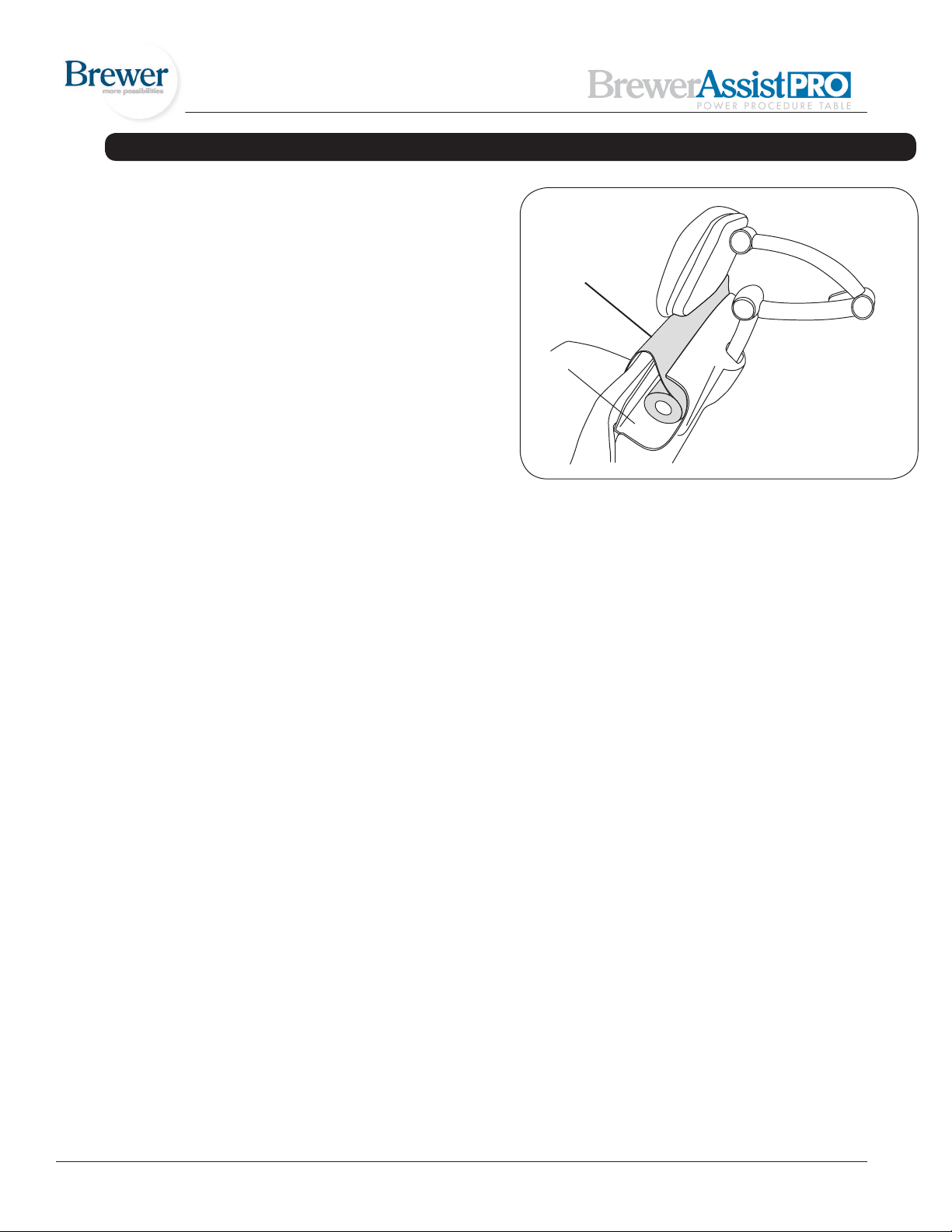
TABLE ADJUSTMENTS (CONTINUED)
Paper Roll (Figure 20)
To change a paper roll, insert the paper through the slot
in the backrest shrouding and set the paper roll in the
holder.
Paper
Slot
Figure 20. Paper Roll
Document # 101522 0608 REV A ER 784 16
Page 17
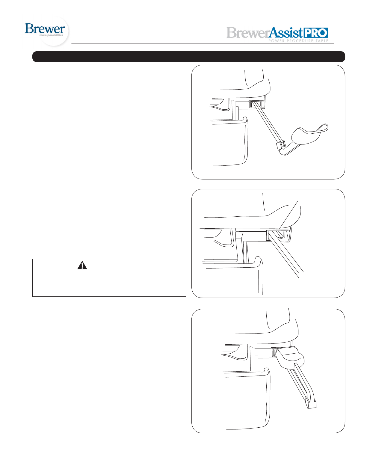
TABLE ADJUSTMENTS (CONTINUED)
Stirrups
Operating the StirrupS (Figure 21)
1. To operate the stirrups, grasp end of stirrup and pull
straight out of the table. Lift up slightly while sliding
the stirrup out.
NOTE: Do not apply any downward pressure when pulling stirrup from table or it may be difcult to move. This
is normal and is part of the stirrup friction locking mechanism
2. Unfold stirrup upward to the fully open position.
3. Adjust the stirrup to the desired length by sliding it in
or out.
Stirrup LateraL adjuStment (Figure 22)
Pull Stirrup out, then unfold
Figure 21. Operating the Stirrups
1. Lift end of stirrup and then rotate outward to
desired position.
2. When the desired position is achieved, lower the stirrup to engage the lateral locking mechanism.
3. Check that lateral locking mechanism is engaged by
attempting to rotate stirrup assembly without lifting on
the stirrup end.
WARNING
Failure to engage the lateral locking mechanism
could allow patient to lose balance resulting in
personal injury to patient.
StOring the StirrupS (Figure 23)
1. To store the stirrups in the table, grasp end of stirrup
and pull straight out to its full extension.
2. Fold stirrup down against bar, then rotate it to the
inner most lateral position and slide it back into the
stowed position.
Lateral Locking Mechanism
Figure 22. Stirrup Lateral Adjustment
Document # 101522 0608 REV A ER 784 17
Figure 23. Storing the Stirrups
Page 18
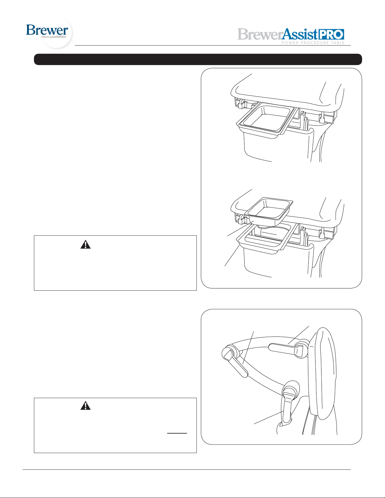
TABLE ADJUSTMENTS (CONTINUED)
Treatment Pan (Figure 24)
NOTE: A safety switch prevents upward motion of the
legrest when the treatment pan tray is extended. This prevents the legrest from contacting the treatment pan tray. If
the legrest upward motion is inoperable, check to ensure
that the treatment pan tray is in its fully stowed position
(inward). A light clicking sound will be heard just before
the treatment pan reaches its fully stowed position.
1. To expose the treatment pan for use, grasp the tray
handle and pull until tray is fully extended (Figure 24).
2. The pan can be easily removed for cleaning with
the tray fully extended. Fully seat pan into tray when
clean.
3. Push the tray handle as far in as it will go to fully stow
the treatment pan after use. A light clicking sound will
be heard just before the pan reaches its fully stowed
position.
Headrest Positions (Figure 25)
WARNING
Make sure headrest is securely locked into position
before use. Failure to have the three handles correctly locked could result in headrest falling during
a procedure which could result in serious personal
injury.
1. To move the headrest, rotate the three handles to
their open position. Move the headrest to its desired
location. Rotate the 3 handles to their locked position
as shown in Figure 25.
2. Each section of the headrest can be adjusted independently by rotating the handle to the open position,
moving the desired section, and then rotating the
handle to the closed position.
Treatment
Pan
Tray
Figure 24. Treatment Pan
Upper Handle
(Locked)
Headrest Handle
(Locked)
NOTE: Make sure all three handles are locked. A handle
is locked correctly when it is pushed past center and
the force of the clamping action pulls the handle into the
locked position and holds it there.
WARNING
If any of the handles fails to lock properly, the
headrest assembly could fall during a procedure.
This could cause severe injury to a patient. Do not
attempt to repair the headrest assembly yourself;
call for service.
Document # 101522 0608 REV A ER 784 18
Lower Handle
(Locked)
Figure 25. Headrest Handles
Page 19
MAINTENANCE
Preventative Maintenance
CAUTION
Failure to perform periodic inspections of the
table could result in personal injury or equipment
damage.
• Periodically inspect the electrical cord to ensure it is
free of cuts or damage.
• Inspect the mechanical functions to ensure satisfactory operation.
• Check fasteners to make sure they are present and
tightened securely.
• Lubricate moving parts (such as back, tilt, and legrest
hinges) with a light machine oil.
• Have your authorized dealer inspect your table every
6 months.
LIMITED WARRANTY
The Brewer Company
GENERAL TERMS AND CONDITIONS
Table Care
CAUTION
The upholstery material is resistant to most medicinal type stains, but may be damaged by solvents
and dyes. Remove any spilled uids from the upholstery immediately.
Clean the table weekly, wiping the painted metal and
plastic surfaces with a clean, soft cloth. If desired, mild
cleaners may be used.
Warranty: The Brewer Company warrants its AssistPRO programmable power table to be free from defects in parts and workmanship under normal use and service for a period of three (3) years from date of shipment. The Brewer Company will not be
responsible for any Product failure due to abuse, misuse, modication or improper use or for any use which exceeds the published
capacity of the Product. Products returned by prepaid freight for inspection and found defective will, at the option of The Brewer
Company, be repaired or replaced at no charge, but no claim for outside labor or other charges will be allowed. Products must
not be returned without proper written authorization from The Brewer Company. Requests for authorization must be in writing and
accompanied by the original purchase order, The Brewer Company invoice number and a copy of the invoice for the Product. THIS
WARRANTY IS EXCLUSIVE AND IN LIEU OF ALL OTHER WARRANTIES AND REMEDIES WHATSOEVER, INCLUDING BUT
NOT LIMITED TO IMPLIED WARRANTIES OF MERCHANTABILITY AND/OR FITNESS FOR A PARTICULAR PURPOSE. NO
AGENT, EMPLOYEE, OR REPRESENTATIVE OF THE BREWER COMPANY HAS ANY AUTHORITY TO MAKE ANY AFFERMATION, REPRESENTATION, OR WARRANTY NOT SET FORTH IN THESE TERMS AND CONDITIONS CONCERNING ANY
PRODUCTS OF THE BREWER COMPANY. THE BREWER COMPANY SHALL HAVE NO LIABILITY WHATSOEVER FOR DAMAGES CAUSED BY TRANSPORTATION, ACCIDENTS, FIRE, UNAUTHORIZED ALTERATION, OR NORMAL WEAR OR ABUSE,
NOR SHALL THE BREWER COMPANY HAVE ANY LIABILITY WHATSOEVER FOR ANY INCIDENTAL OR CONSEQUENTIAL
DAMAGES, including without limitation, lost prots or any such damages arising from (a) the design, manufacture, sale, delivery,
installation, repair, operation or use of products of The Brewer Company or any part thereof, (b) any actual or alleged failure or defect in products of The Brewer company or any part thereof, or (c ) any actual or alleged breach or non-performance by The Brewer
Company of this limited warranty.
Freight Claims: Upon receipt, merchandise should be carefully examined to ascertain that proper amount has been received in
good condition. Any claim for shortage or damage must be made with delivering carrier within ve (5) days from receipt of goods.
We do not assume any responsibility for loss or damage in transit, and compensation for such loss must be obtained from the carrier
Document # 101522 0608 REV A ER 784 19
 Loading...