

Page 1
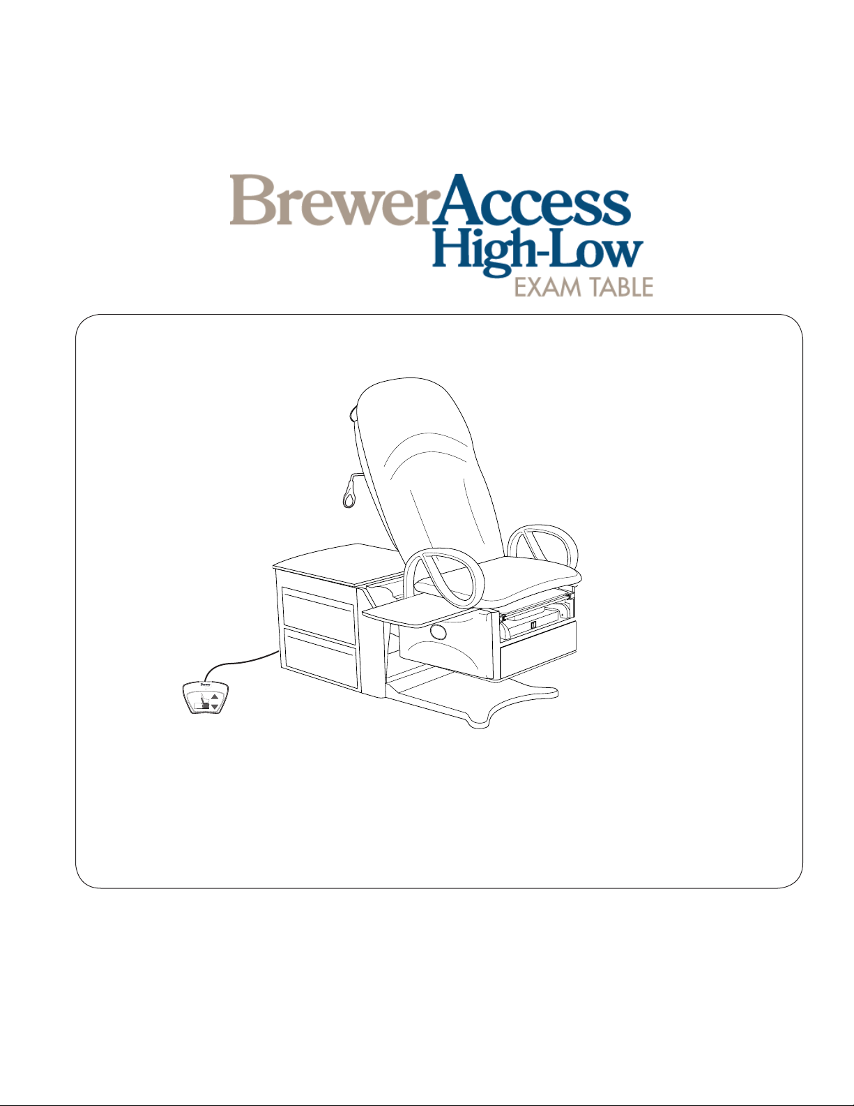
Installation & Operation Manual
Br
e
wer
Important Information ............................................2
Safety Information .................................................3
Component Identication ......................................3
Specications ........................................................4
Electrical Requirements ........................................4
Installation .............................................................5
The Brewer Company, LLC
N88 W13901 Main Street, Suite 100
Menomonee Falls, WI 53051
P 1.888.Brewer.1
Document # 100452 RevL 1 Printed in USA © 2013
F 262.251.2332
www.brewercompany.com
Operation ..............................................................8
Table Adjustments ...............................................15
Maintenance ........................................................17
Troubleshooting ................................................... 18
Options, Accessories & Common Service Parts..24
Limited Warranty .................................................25
Page 2
IMPORTANT INFORMATION
General
The Brewer Access High-Low Exam Table Model 6000
Series is designed to provide positioning and support of
patients during general examinations conducted by qualied medical professionals. Read and understand all operating instructions, safety information, and maintenance
requirements contained in this manual prior to operating
the table. Become familiar with all of the table functions
before using it with a patient.
The Brewer Access High-Low Exam Table is primarily
used in examination rooms for general examinations and
minor procedures. The wide variety of positions provided
by one or two powered motions, slide-out leg support,
slide-out leg extension, stirrups and treatment pan, create
a safe and convenient patient positioning table for most
examinations and procedures performed in the doctor’s
ofce.
The table is easily adjusted to a wide variety of positions
using the convenient foot control provided with the table.
The table height can be adjusted from 19” to 37”. The
table seating surface on models 6001, 6501, and 6801
can be moved from the normal horizontal position to an
angle of 5°. The backrest can be adjusted from a at lying down position, to an 80° angle for seating.
Service
If you require assistance with the installation or operation
of your Brewer table, call the Brewer Customer Service
Department at (1-888-Brewer1). Our trained staff will
attempt to assist you in correcting the problem directly
over the phone. If service is required, a factory authorized
technician will be sent to your location.
Please ll in the following information for use when calling
the Brewer Company or your distributor with questions
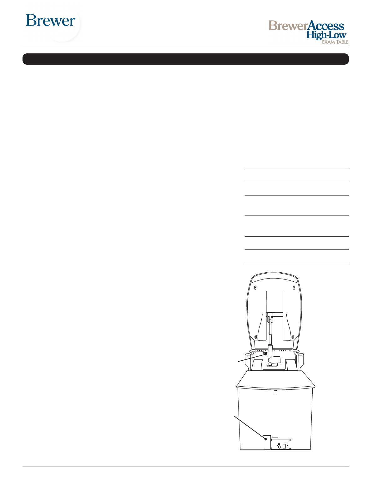
regarding your unit. See Figure 1 for model and serial
number location.
Date of Purchase
Serial Number
Model Number
Authorized
Dealer Name
Dealer
Phone Number
Dealer Address
In addition to the electronically controlled positions noted
above, several manual adjustments are available:
• The leg support can be extended 14” for the patient
prone position. If more length is needed, the leg extension can be pulled out to provide an additional 6”.
• Stirrups may be manually extended through innite
positions and four lateral positions.
• A removable treatment pan is built-in underneath the
leg extension for use during examinations.
• Grab bars attached to each side of the table may be
rotated out of position or removed for improved access to the patient.
• A pass through work surface, stored under the seat,
may be pulled out from either side of the table.
• Storage drawers at the front and side of the table may
be used for supplies. The pass through side drawers
may be pulled out from either side of the table.
• A storage cover at the rear of the table can be lifted to
store paper rolls.
Models 6000, 6001, 6500 and 6501 are designed to
accommodate a maximum patient weight of 450 lbs.
Models 6800 and 6801 are designed to accommodate
a maximum patient weight of 700 lbs.
Serial Number
Model Number
Figure 1. Model and Serial Number Location
Document # 100452 RevL 2 Printed in USA © 2013
Page 3
Br
e
wer
SAFETY INFORMATION
Safety Information
The primary concern of The Brewer Company is that the
equipment is operated and maintained with the safety of
the patient and healthcare staff in mind. To ensure safe
and reliable operation:
• Read and understand all instructions in this manual
before attempting to install or operate the unit.
• Ensure that appropriate personnel are informed on
the manual contents. This is the responsibility of the
purchaser.
• Ensure that this manual is located near the table, or if
possible permanently afxed to the table.
COMPONENT IDENTIFICATION
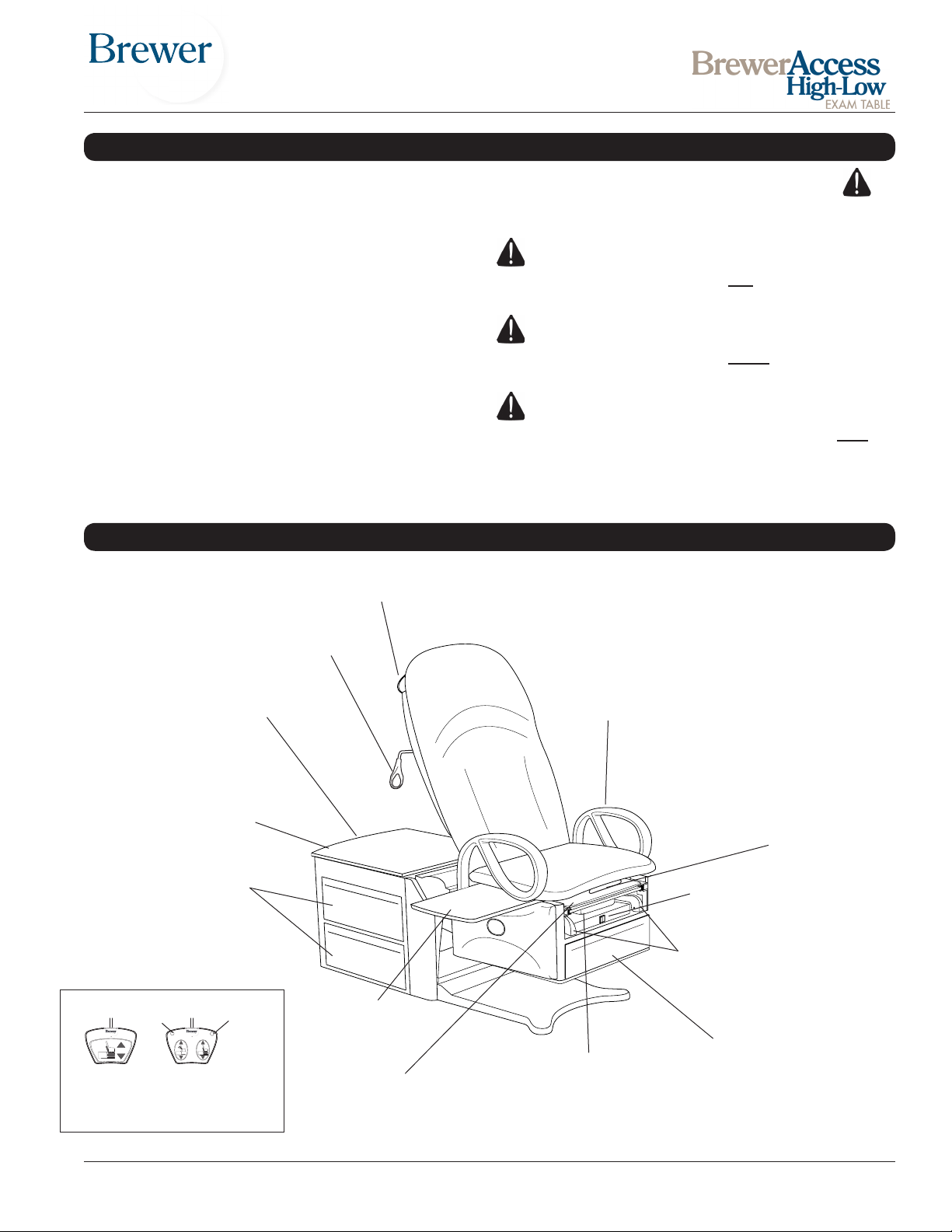
Paper Roll Holder
Failure to follow instructions with this symbol
could result in serious personal injury and/or damage
to the unit.
DANGER indicates an imminently hazardous
situation which, if not avoided, will result in death or
serious injury.
WARNING indicates a potentially hazardous
situation which, if not avoided, could result in death
or serious injury.
CAUTION indicates an imminently or poten-
tial hazardous situation which, if not avoided, may
result in serious injury and/or equipment damage.
Back Release Handle
(Models 6000/6001)
Safety On/Off Switch
(located on back of cabinet)
Paper Storage
Compartment Lid
Pass Through
Drawers
Stop
STOP
Model
6000/6001
Document # 100452 RevL 3 Printed in USA © 2013
Model
6500/6501
6800/6801
Foot Controls
To Chair
RETURN
TO CHAIR
Return
Pass Through
Work Surface
- Slide-out Leg Support
- Slide-out Leg Extension
Figure 2. Component Overview
(located under Leg Support Pad)
Grab Bar
Pelvic Tilt Bar
Drawer Warmer Switch
(Models 6001, 6501 & 6801 only)
Stirrups
Front Drawer
Treatment Pan
Page 4
SPECIFICATIONS
Weight of Table (Models 6000, 6001, 6500 & 6501) .. 395 lbs.
Weight of Table (Model 6800) .................................. 423 lbs
Weight of Table (Model 6801) .................................. 432 lbs
Load Rating (maximum):
- Seat/Back 6800/6801 .......................................... 700 lbs.
- Seat/Back 6000/6001/6500/6501 ........................ 450 lbs.
- Leg Support .......................................................... 50 lbs.
- Leg Extension ....................................................... 50 lbs.
- Pass Through Work Surface ................................. 15 lbs.
- Grab Bars ............................................................ 100 lbs.
Back Section Range .................0° (horizontal) to +80° ± 5°
Table Top Height Range .............18 ± 0.5 in. to 37 ± 1.0 in.
Pelvic Tilt Range
(Models 6001/6501/6801 Only) ....0° (horizontal) to 5° (up)
Upholstery Dimensions:
Upholstered Top ........................ 28.0 in. wide x 60 in. long
Upholstered Leg Support……15.25 in. long x 18.5 in. wide
Upholstered Leg Extension…....6.0 in. long x 15.5 in. wide
Overall Length ................................................... 60 in. long
With Leg Support Extended............................... 72 in. long
With Leg Extension Extended ........................... 78 in. long
Electrical Requirement
6000/6500/6800 ........115 VAC nominal, 60 HZ, 5.8 amps max.
6001 .........................115 VAC nominal, 60 HZ, 6.3 amps max.
6001/6501/6801 W/Outlet ...115 VAC nominal, 60 HZ, 9.3 amps
max.
Fuse Rating:
Control Box Fuse Rating, 120V Models ............ 250V/2.5A
Option/Warmer Fuse Rating .............................. 250V/1.0A
Option/Warmer & Outlet Fuse Rating ................ 250V/3.0A
Duty Cycle (10%)
.................... 2 minutes on / 18 minutes off (motor run time)
Power Cord............... Extends 70 in. (Minimum) from table.
120V Models: 18 AWG / 3 conductor, SJT grey jacketed
junior hard service with hospital plug or detachable
power cord.
Type of protection
against electrical shock
Model 6000, 6500 and 6800 ........ Class 2 Double Insulated
Models 6001, 6501 and 6801 ................. Class 1 Grounded
Type of protection
against electrical shock ............................... B applied parts
Type of protection against ingress of water……. Ordinary
Can accept paper rolls of 18 in. x 3.0 in.
.................................................................. or 21 in. x 3.0 in.
Certications* .............................. UL60601-1; IEC60601-1;
..................................................CAN-CSA C22.2 No. 601.1
Operating Conditions:
Temperature Range ........................................... 65° to 85°F
Relative Humidity..............................................10% to 90%
Transportation and Storage
Temperature .................................................-20°F to 150°F
Humidity............................................................10% to 90%
* UL classied in the United States and Canada
per the standards listed above.
ELECTRICAL REQUIREMENTS
WARNING
When performing a cauterization or similar treatment, the patient must be insulated from the metal
portions of the table by non-conductive material.
Failure to do so may result in electrical shock or
burns to the patient.
Do not use any power supply other than that
listed on the rating label (Figure 1). Failure to do
so may result in serious injury and/or equipment
damage.
CAUTION
CAUTION
WARNING
Use 115 VAC, 60 Hz as noted on the rating label.
Failure to do so may result in electrical shock to
personnel and will result in damage to the table.
WARNING
Do not use this table in an explosive or oxygenenriched atmosphere. Failure to do so may result
in serious personal injury or death.
Document # 100452 RevL 4 Printed in USA © 2013
This product has been evaluated with respect to
electrical shock, re, and mechanical hazards only
in accordance with UL60601-1; IEC60601-1;
CAN/CSA C22.2 No. 601.1
Electromagnetic Interference
This product is designed and built to minimize electromagnetic interference with other devices; however, if interference is noticed between another device and this product,
remove the interfering device from the room or plug this
product into an isolated circuit.
Page 5
INSTALLATION
Overview
Perform the following sequence in order when setting up
the table:
- Uncrating
- Leveling the Base
- Installing Grab Bars
Uncrating
NOTE: Inspect all boxes and contents for damage. Report any damage to the carrier immediately.
CAUTION
To avoid damaging the table’s upholstery or painted surfaces, DO NOT use a knife or other sharp
object to open the packaging. Also, to avoid damaging the table lift only at points indicated in Figure
3. Do not lift at other points as indicated by the
note in Figure 4.
WARNING
The table weighs approximately 395 lbs. Use
enough personnel to remove the table from the
shipping pallet. Also, use proper lifting techniques
when lifting. Failure to do so could result in serious injury.
CAUTION
Do not use the stirrups to lift or move the table.
The Leg Support may be used to lift the table. Do
not pull on the Leg Support to slide the table.
See SPECIFICATIONS table for electrical rating of
this unit. The three-pronged grounding plug on the table
power cord must be plugged into a matching threepronged, grounded, non-isolated, correctly polarized 115
VAC receptacle.
CAUTION
Do not plug power into table prior to removal of all
packaging materials.
1. Remove stretch wrap surrounding table.
2. Cut and remove banding and protective foam tube
attaching table to pallet.
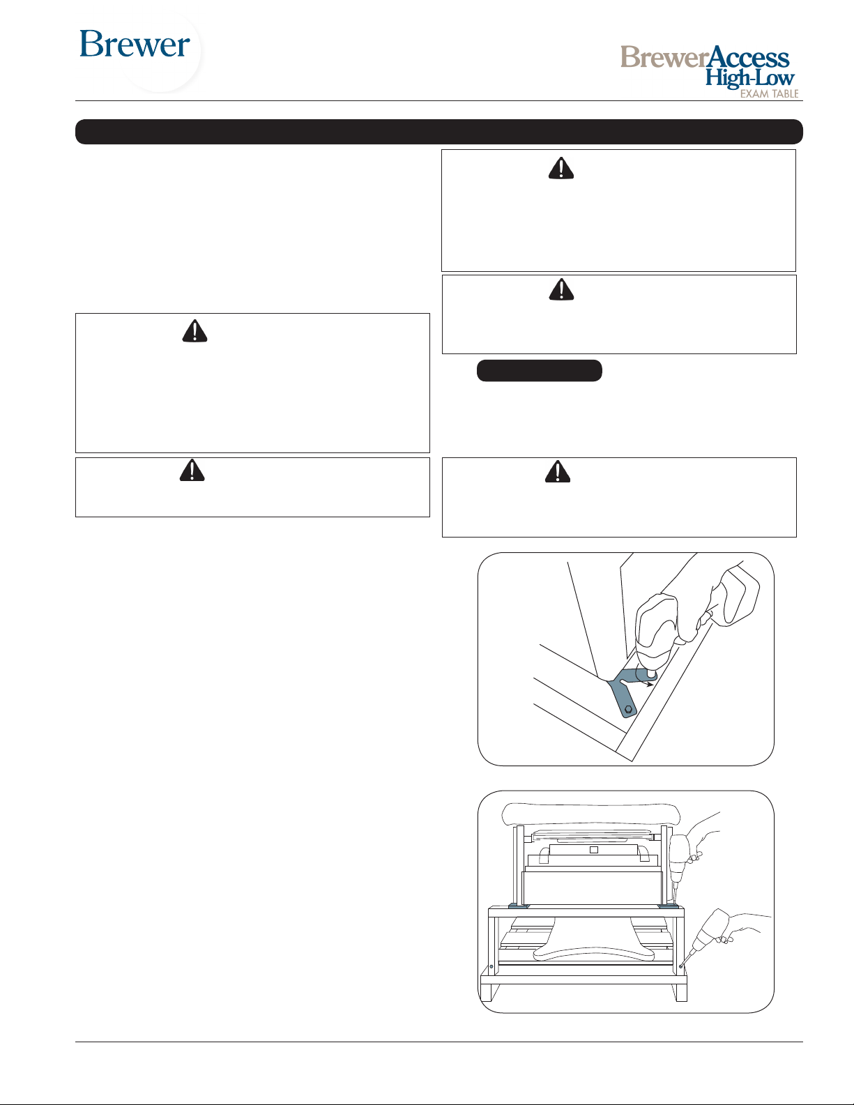
3. Remove the 6 steel shipping brackets securing the table
to the pallet, one at each of the four corners and one
at the middle on each side of the table (Figure 3). The
brackets engage with the table levelers to hold the table
securely to the pallet. Remove the 2 bolts from each
bracket using a 7/16” socket or wrench. Take care not
to scratch the unit when turning the wrench. Remove
brackets from levelers once bolts are removed.
4. Remove the 2 screws attaching the spacers on either
side of the wooden U-shaped brace located under the
front corners of the cabinet (Figure 4). Remove the
2 screws attaching the U-shaped brace to the pallet
(Figure 4).
CAUTION
Do not lift table by seat upholstery. Damage to
the pelvic tilt mechanism and/or upholstery may
occur.
Figure 3. Remove Shipping Brackets
5. Remove the foot control from the rear drawer. Insert the
foot control cord into the receptacle at the bottom of the
rear panel (Figure 10). Secure with locking ring.
Figure 4. Remove Spacers and U-Brace
Document # 100452 RevL 5 Printed in USA © 2013
Page 6
INSTALLATION (continued)
6. Remove the gray power cord from the rear drawer.
Plug the power cord into the socket at the bottom of
the rear panel (Figure 10). Plug the power cord into
a 120 Volt grounded receptacle.
7. Make sure the black On/Off Switch at the back of the
table is on (Figure 14 ).
8. Depress the switch on the foot control for lifting the
seat section until all the weight is removed from the
wooden U-shaped brace. Remove the brace and
spacers.
9. Unplug the power cord from the table and the
receptacle. Remove the foot control from the table.
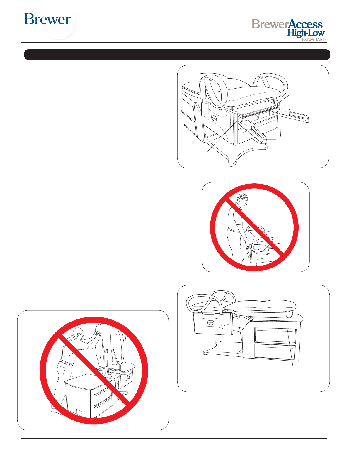
Observe the following cautions when lifting the table
from the pallet.
• Do not lift table by stirrups (Figure 5).
• Lift front of table by leg support (Figure 5). Pull leg
support (not leg extension) out approximately 6”.
• Do not lift by upholstery (Figure 6).
Do Not Use
Leg Extension
to Lift
DO NOT LIFT BY
STIRRUPS!
Use Leg
Support
Figure 5. Stirrups & Leg Support
• Lift rear of table by pushing top rear pass-through
drawer to one side and using opening as a hand hold
(Figure 7) .
• Whenever moving table, lift and lower. Do not drag
table. Damage to the levelers may occur.
• Do not push on backrest. Damage to the actuator
(mechanism that raises and lowers the backrest may
occur (Figure 8).
Figure 6. Do Not Lift by Upholstery
Pull Leg Support out
slightly and lift here. Do not
lift by the Leg Extension.
See Figure 4.
Lift table at these points only
Figure 7. Table Lift Points
Slide drawer and
lift here
Figure 8. DO NOT Push on Backrest
Document # 100452 RevL 6 Printed in USA © 2013
Page 7
INSTALLATION (continued)
Leveling the Table
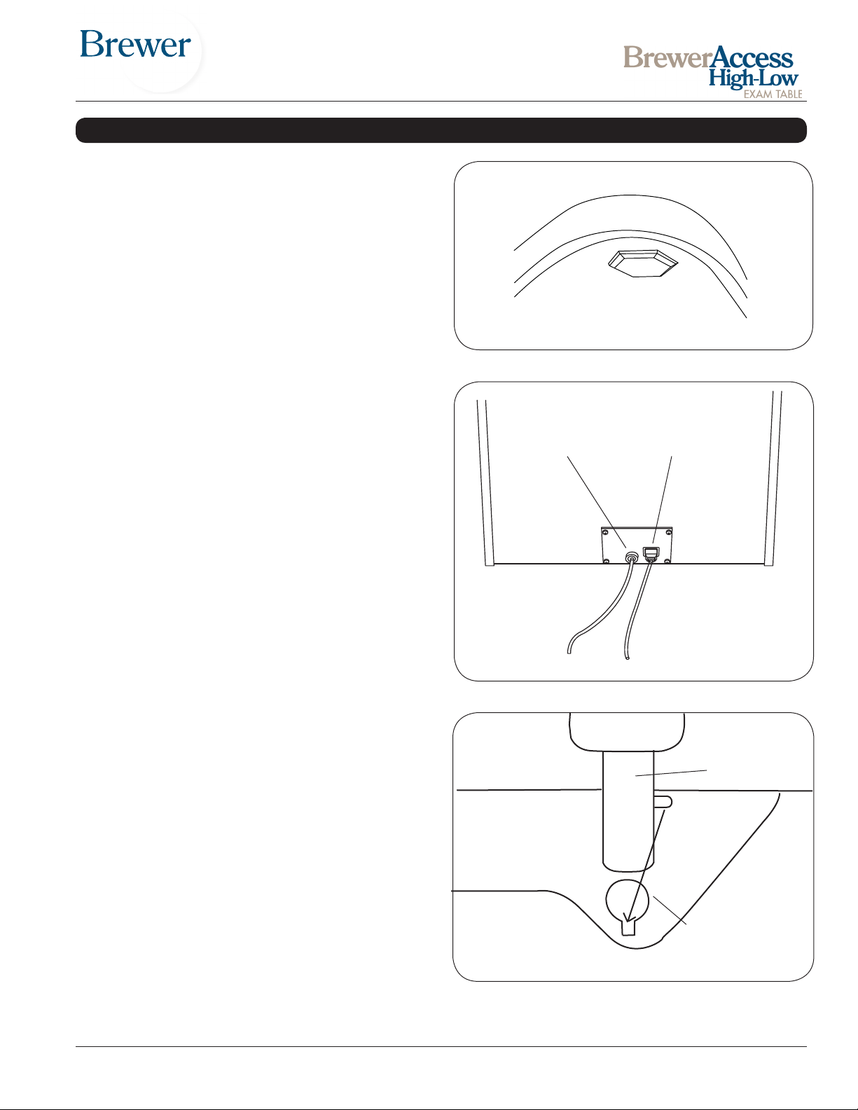
A leveling screw pad (Figure 9) is located in six places
under the table’s base and rear cabinet. Adjust the six
leveling pads to achieve a solid, level installation.
Installing the Power Cord
(Models 6001, 6501 and 6801)
1. Remove the power cord from the shipping bag.
2. Insert the female plug end of the power cord into the
receptacle on the table (Figure 10). Make sure the
tabs are aligned and the plug is fully seated.
Note: The power cord is installed at the factory on model
6000, 6500 and 6800.
Installing the Foot Control
1. Insert the male plug of the foot control cord into the
receptacle on the table (Figure 10). Make sure the
pins are properly orientated and the plug is fully
seated.
2. Turn the locking ring clockwise to secure the plug to
the table.
Installing Grab Bars
1. Remove from drawer.
2. Grab bars t on either side.
3. Align pin on grab bar shaft with mating slot on side of
table. See Figure 11.
4. Push grab bar all the way down and rotate to front of
table.
5. Push grab bar down until it engages to prevent left or
right movement.
View of underside of base
Figure 9. Leveling Screw Pad (located under table)
Foot Control Power Cord
Note :
Some models may
not have a detachable
power cord.
Figure 10 Power Cord and Foot Control.
Grab Bar
Mounting Support
Figure 11. Grab Bar
Document # 100452 RevL 7 Printed in USA © 2013
Page 8
OPERATION
General
DANGER
Do not use this table in an explosive or oxygenrich atmosphere. To do so will result in an explo-
sion or re.
WARNING
If the table malfunctions, immediately remove your
foot from the controls, unplug the power cord from
the electrical receptacle, and assist the patient
from the table. If table continues to malfunction,
call for service. Do not attempt to repair table yourself.
WARNING
Before initiating power, keep personnel and equipment clear of the table movement to avoid personal injury or equipment damage.
CAUTION
The foot control is moisture resistant and runs on
low voltage, eliminating shock hazards. However,
to avoid temporary or permanent damage to the
foot control, do not immerse in water or liquids.
CAUTION
Keep foreign objects away from foot control. To
avoid accidental operation, be sure the foot control is NOT positioned below the front of the table.
Failure to do so could result in unwanted motion
and possible damage to the table.
NOTE: For optimum table performance, allow the table to
reach room temperature before operating.
NOTE: The table is not designed for continuous operation. The control system includes a thermal overload
safety switch to protect from overheating. If the table is
operated continuously causing the control to exceed its
allowable operating temperature, the thermal overload
safety switch will shut off. If normal operation ceases,do
not attempt to operate the table. Allow the table to cool
for 10-15 minutes before attempting to use again. The
thermal overload switch will automatically reset when it
has reached a safe operating temperature.
NOTE: The control system is protected by a fuse to
prevent excessive current draw which could damage
the system. If operation does not resume after a cooling
period of one hour, contact your dealer or an authorized
service center for repair.
WARNING
Keep personnel and equipment clear of table before initiating movement to avoid personal injury
or damage to the equipment.
NOTE: Each control function will automatically stop
moving when either the UP or DOWN travel limit is
reached. If the foot pedal is pressed with travel at its
limit, the actuator will not operate. Sensors prevent the
actuator motor from operating when travel limit has
been reached, preventing wear of the actuator.
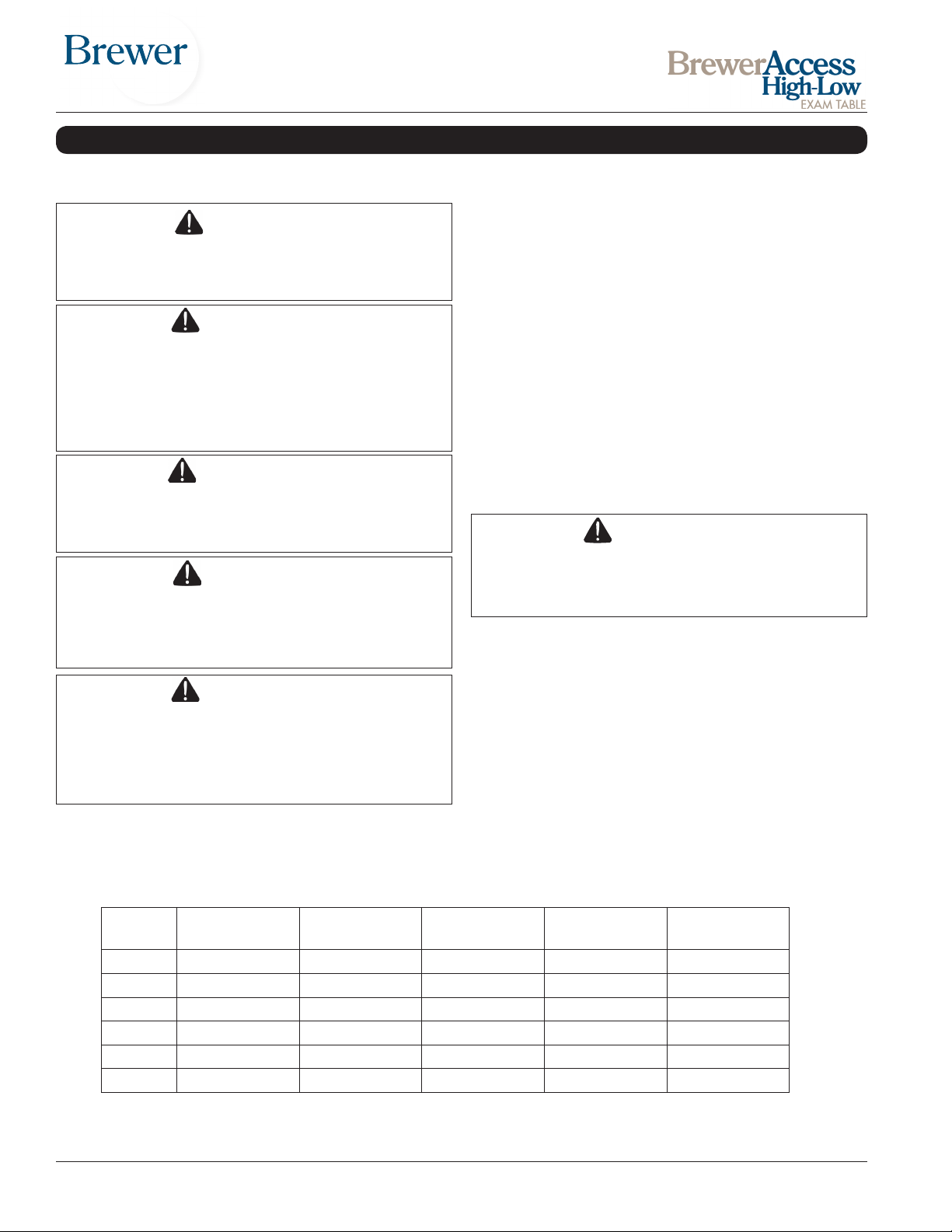
Model Congurations
Model Power Back Pneumatic
Manual Back
6000 X
6001 X X X
6500 X X
6501 X X X X
6800 X X
6801 X X X X
Document # 100452 RevL 8 Printed in USA © 2013
Pelvic Tilt Drawer
Warmer
Return To
Chair
Page 9
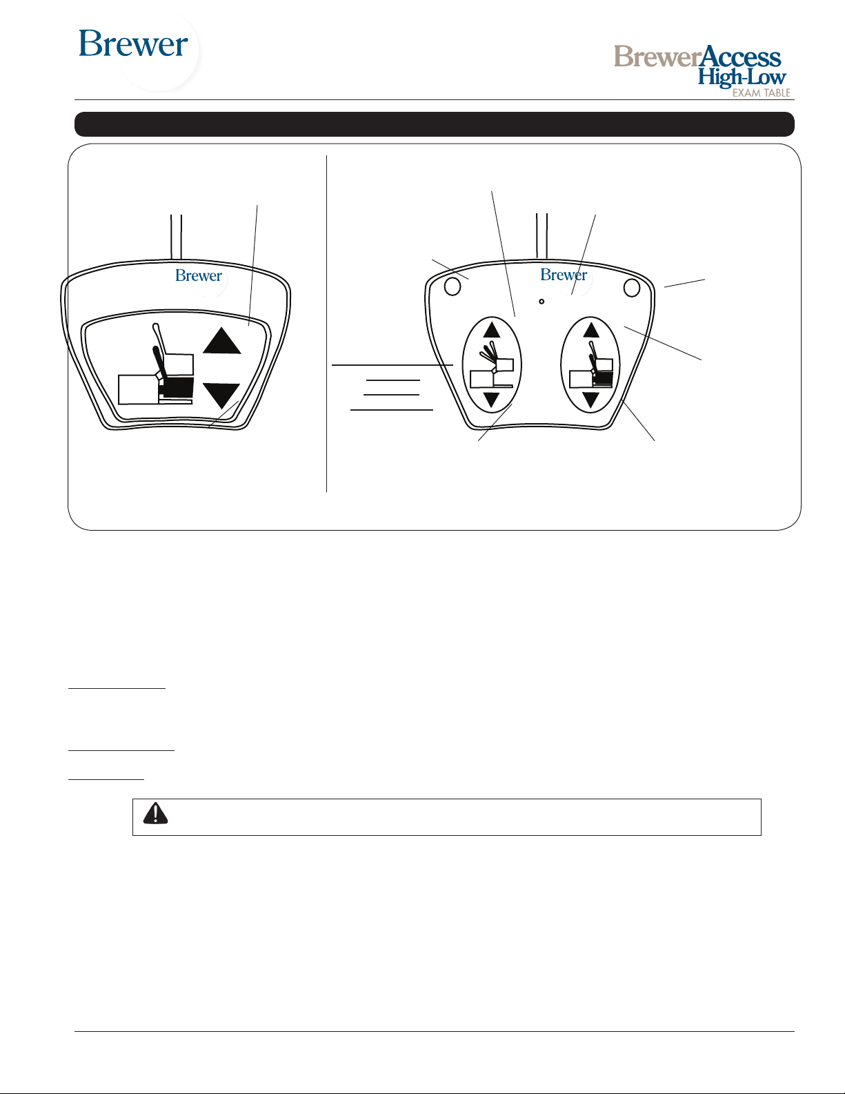
OPERATION (continued)
(Raises the entire
TABLE DOWN
(Lowers the entire
table downward)
MODELS 6000 & 6001
TABLE UP
table upward)
BACK UP
(Raises the back)
EMERGENCY STOP (RED)
(Stops all
functions
when pressed)
STOP
Pressing any button
stops all
functions
when pressed
BACK DOWN
(Lowers the back)
MODELS 6500, 6501,6800 & 6801
Figure 12. Foot Controls
GREEN LIGHT
(Lights when power
to the foot control is ON)
RETURN
TO CHAIR
TABLE DOWN
(Lowers the entire
table downward)
RETURN TO CHAIR
(BLUE)
(Returns table
to chair position
when pressed)
TABLE UP
(Raises the entire
table upward)
Models 6000 & 6001
Models 6000 and 6001 are equipped with a single foot pedal that controls the raising/lowering of the table.
Models 6500, 6501, 6800 & 6801
Models 6500, 6501, 6800 and 6801 are equipped with a dual pedal foot control that controls the raising/lowering of the
table and raising/lowering of the seat back. In addition, the control features the following:
Return to Chair: When pressed, the table automatically returns to the low chair position. The seat back will rise to the full
up position and the table will lower to the full down position and stop. If the Emergency Stop or either pedal is pressed
while the table is in motion, the system will return to manual mode and all motion will stop.
Emergency Stop: When pressed, stops the motion of all functions.
Green Light: Indicates that there is power to the foot control (Safety On/Off switch at back of table is ON).
CAUTION Do not leave patient unattended when using the Return To Chair feature.
Document # 100452 RevL 9 Printed in USA © 2013
Page 10
OPERATION (continued)
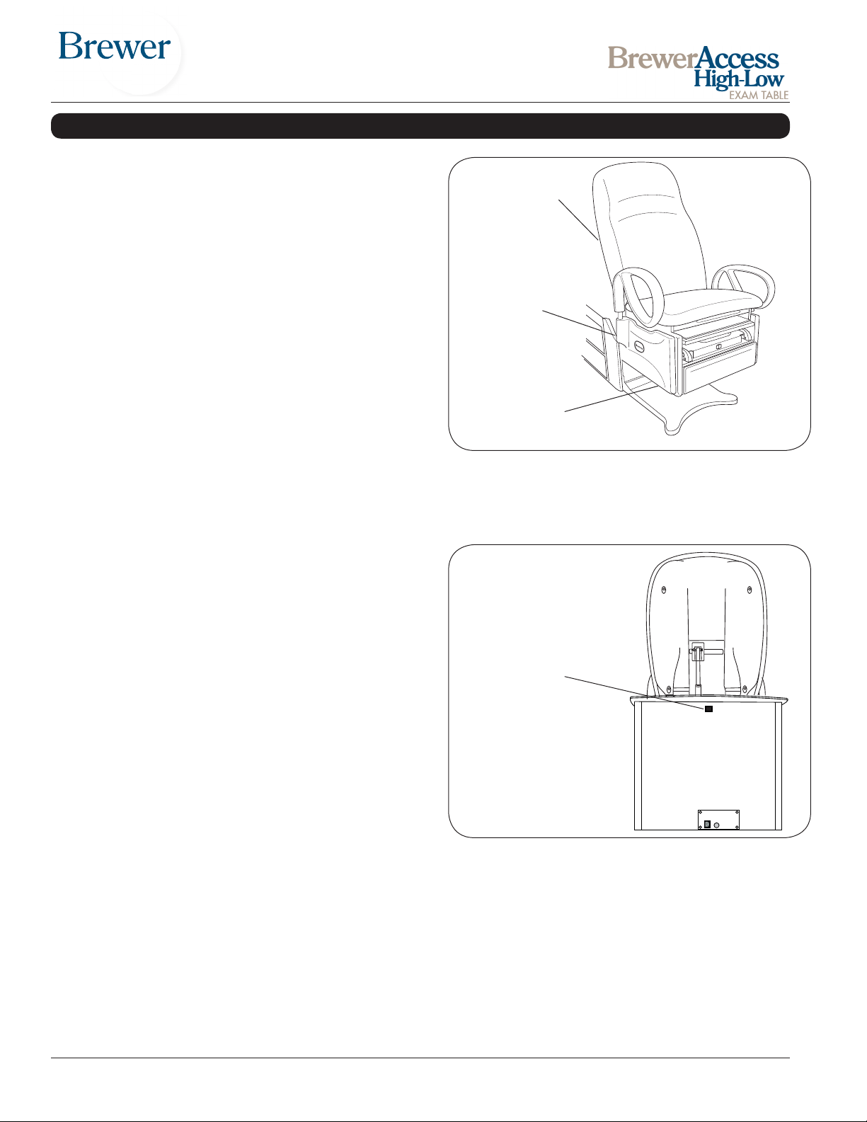
Seat and Backrest Safety Switches
All Models
All models are equipped with safety switches. They are
located inside the backrest cover, on the seat back and
on the bottom of the chair assembly. Each safety switch
automatically stops the lowering function if an obstruction
is encountered (Figure 14).
Powered Backrest (Models 6500, 6501, 6800 and 6801)
Models 6500, 6501, 6800 and 6801 are equipped with
safety switches on the rear of the backrest which automatically stops the lowering function of the seat and back
if an obstruction is encountered.
Depress the BACK UP pedal and remove the obstruction.
Pneumatic Manual Backrest (Models 6000 & 6001)
The safety switches automatically stop the lowering function of the seat if an obstruction is encountered.
Safety On/Off Switch
All Models
The On/Off switch (located on the back of the rear cabinet,
Figure 14) can be set to the OFF position to disable all
movement of the table. Power to the drawer warmer (if so
equipped) and other portions of the table will remain on.
Safety Switches
Located Inside
Backrest Cover
Safety Switches
Located Inside
Seat Back
(both sides)
Safety Switches
Located on
Seat Bottom Plate.
Figure 13. Seat and Backrest Safety Switches
Safety On/Off Switch
Located on
Back of Table
Figure 14. On/Off Safety Switch
Document # 100452 RevL 10 Printed in USA © 2013
Page 11
OPERATION (continued)
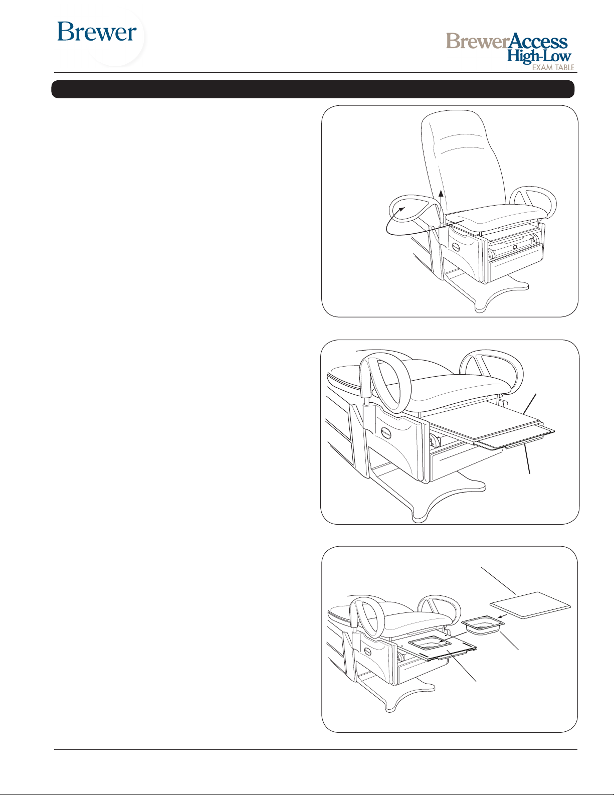
Grab Bars
In the forward (normal use) position the grab bars lock
into place preventing left or right rotation.
The grab bars can be rotated to the side of the table for
improved access to the patient. Pull up on the grab bar
and rotate to the desired position. The grab bar locks in
the front and rear position (Figure 15).
NOTE: The grab bar can be removed from the table by
pullling up on the grab bar, rotating it to the 90° position,
and then lifting it out of it’s holder.
Leg Support
The leg support is located under the seat cushion. (Figure
16), It can be extended 14” for the patient prone position.
Leg Extension
If more length is needed, the leg extension can be pulled
out to provide an additional 6” (Figure 16)
Pull up to rotate
Push down to
lock in place
Figure 15. Grab Bar Adjustment
Leg
Support
Leg
Extension
Figure 16. Leg Support and Extension
Leg Support Pad
Treatment Pan
A removable treatment pan is built-in underneath the
leg support pad for use during examination. Pull the leg
support fully out and remove the leg support pad or slide
it back under the seat to access the pan (Figure 17). Remove the treatment pan for cleaning.
Figure 17. Treatment Pan
Document # 100452 RevL 11 Printed in USA © 2013
Treatment Pan
Leg Support
Page 12
OPERATION (continued)
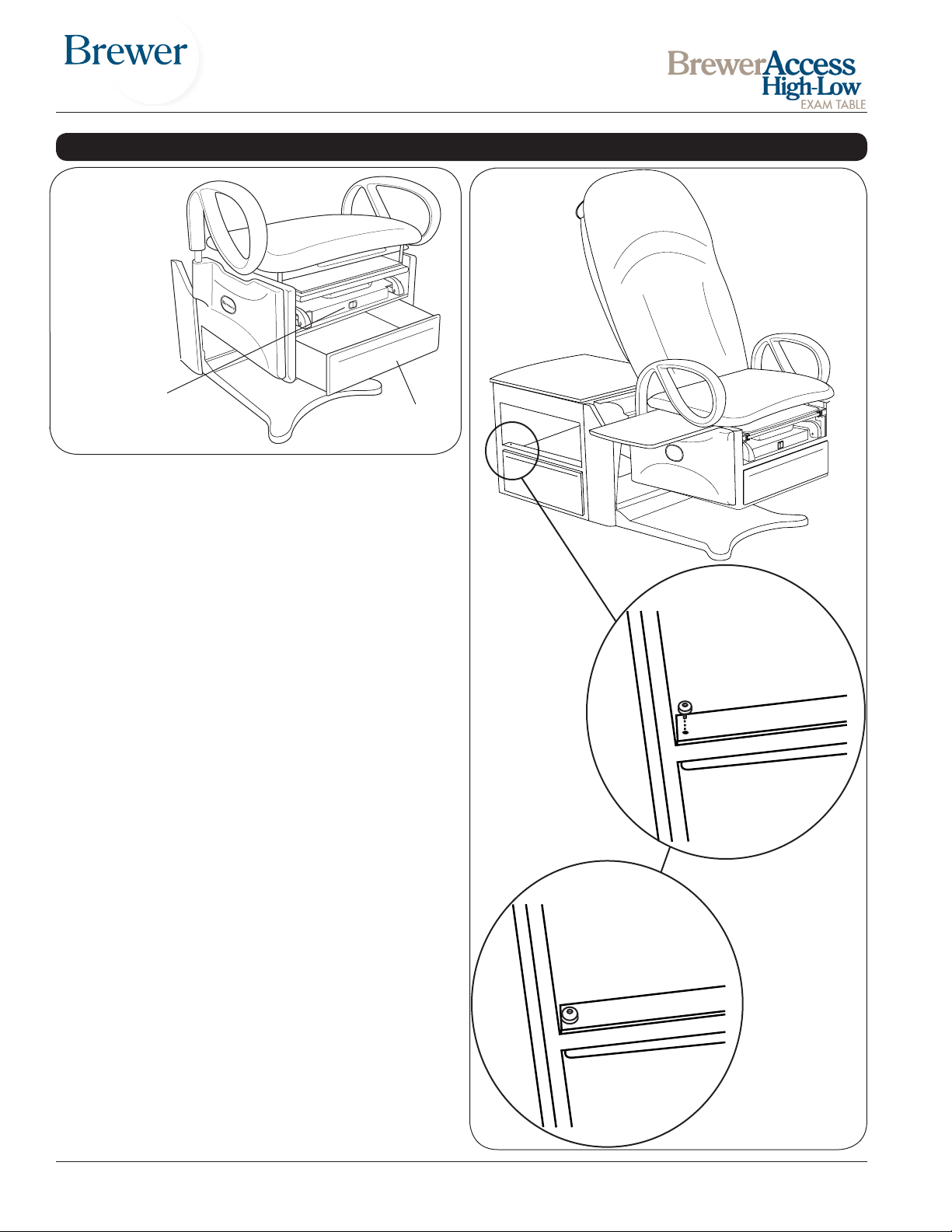
Drawer Warmer On/Off
Switch (Models 6001,6501
and 6801 only)
Figure 18. Drawer Warmer Switch and Front Drawer
Front Drawer
Front Drawer
A storage drawer for supplies is located at the front of the
table. Models 6001, 6501 and 6801 are equipped with
a drawer warmer that is turned on by a switch located
above the drawer (Figure 18).
Pass Through Side Drawers
Two storage drawers are built into the table cabinet for
supplies (Figure 19). The drawers may be pulled out from
either side of the table.
Installing Drawer Stops
The Brewer Access High-Low Exam Tables are supplied
with two drawer stops for the side pass through drawers.
If you wish to restrict the drawers to opening only on one
side, simply install one drawer stop per drawer on the opposite side the drawer is to be opened (See Figure 19.)
To install drawer stops:
Br
e
wer
1. Pull drawers out on the side of desired use.
2. Screw in one drawer stop, one for each drawer on
opposite side of cabinet. (Figure 19).
Figure 19.
Document # 100452 RevL 12 Printed in USA © 2013
Page 13
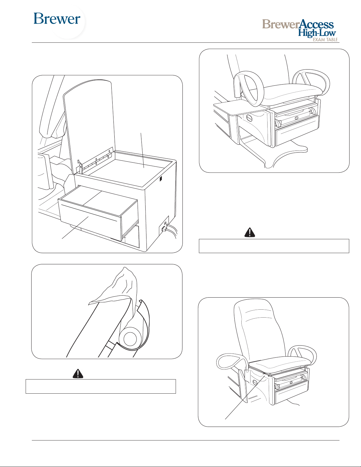
Paper Storage
With the seat back in the upright position, lift the lid on the paper
storage compartment to access stored paper rolls (Figure 20).
Paper Storage
Figure 21. Pass Through Work Surface
Pass Through Work Surface
A pass through work surface, stored under the seat (Figure 21), may be pulled out from either side of the table.
Grasp the edge of the work surface and pull until it is fully
extended. Push it fully in to stow after use.
Pass Through Side Drawers
Figure 20. Side Drawers & Paper Storage
Figure 22. Paper Roll Installation
CAUTION
Do not use paper roll with a diameter greater than
3” or back rest safety switch will not operate.
Paper Roll Holder
To change a paper roll, place the paper into the holder
located on the rear of the seat back (Figure 22). Pull
the end of the roll over the top of the seat back and
place in the desired position.
CAUTION
The work surface is intended to support a maximum of 15 lbs.
Removing the Work Surface for Cleaning
1. Push work surface in, to reveal a white plastic screw.
2. Remove the white plastic screw. (Figure 23.)
3. Pull the work surface toward you and remove it.
4. Reinsert screw after replacing work surface.
Plastic Screw
Figure 23. Location of White Plastic Stop Screw
Document # 100452 RevL 13 Printed in USA © 2013
Page 14
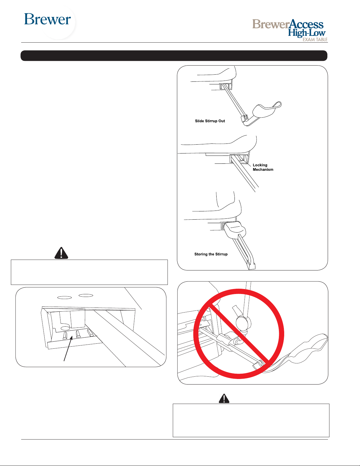
OPERATION (continued)
Adjustable Stirrups
Operating the Stirrups (Figure 24)
1. To operate the stirrups, grasp end of stirrup and pull
straight out of the table. Lift up slightly while sliding
the stirrup out.
NOTE: Do not apply any downward pressure when pulling stirrup from table or it may be difcult to move. This
is normal and is part of the stirrup friction locking mechanism
2. Unfold stirrup upward to the fully open position.
3. Adjust the stirrup to the desired length by sliding it in
or out.
Stirrup Lateral Adjustment
1. Lift end of stirrup and then rotate outward to
desired position.
2. When the desired position is achieved, lower the stirrup to engage the lateral locking mechanism (Figure
25).
3. Check that lateral locking mechanism is engaged by
attempting to rotate stirrup assembly without lifting on
the stirrup end.
See enlargement
(Figure 20)
WARNING
Failure to engage the lateral locking mechanism
could allow patient to lose balance resulting in
personal injury to patient.
Close Up of Locking Mechanism
Figure 25. Stirrup Locking Mechanism
Storing the Stirrups
1. To store the stirrups in the table, grasp end of stirrup
and pull straight out to its full extension.
2. Fold stirrup down against bar, then rotate it to the
inner most lateral position and slide it back into the
stowed position.
Figure 24. Stirrups
Figure 26. Afx No Attachments!
CAUTION
Do not use any part of the stirrup for attachment of any
device (Figure 26). Warranty will be voided. Use support
adapters to attach clamps, then attach knee crutches to
clamps. If adapters are not currently installed, order PN
100550 (See page 24 for accessories).
Document # 100452 RevL 14 Printed in USA © 2013
Page 15
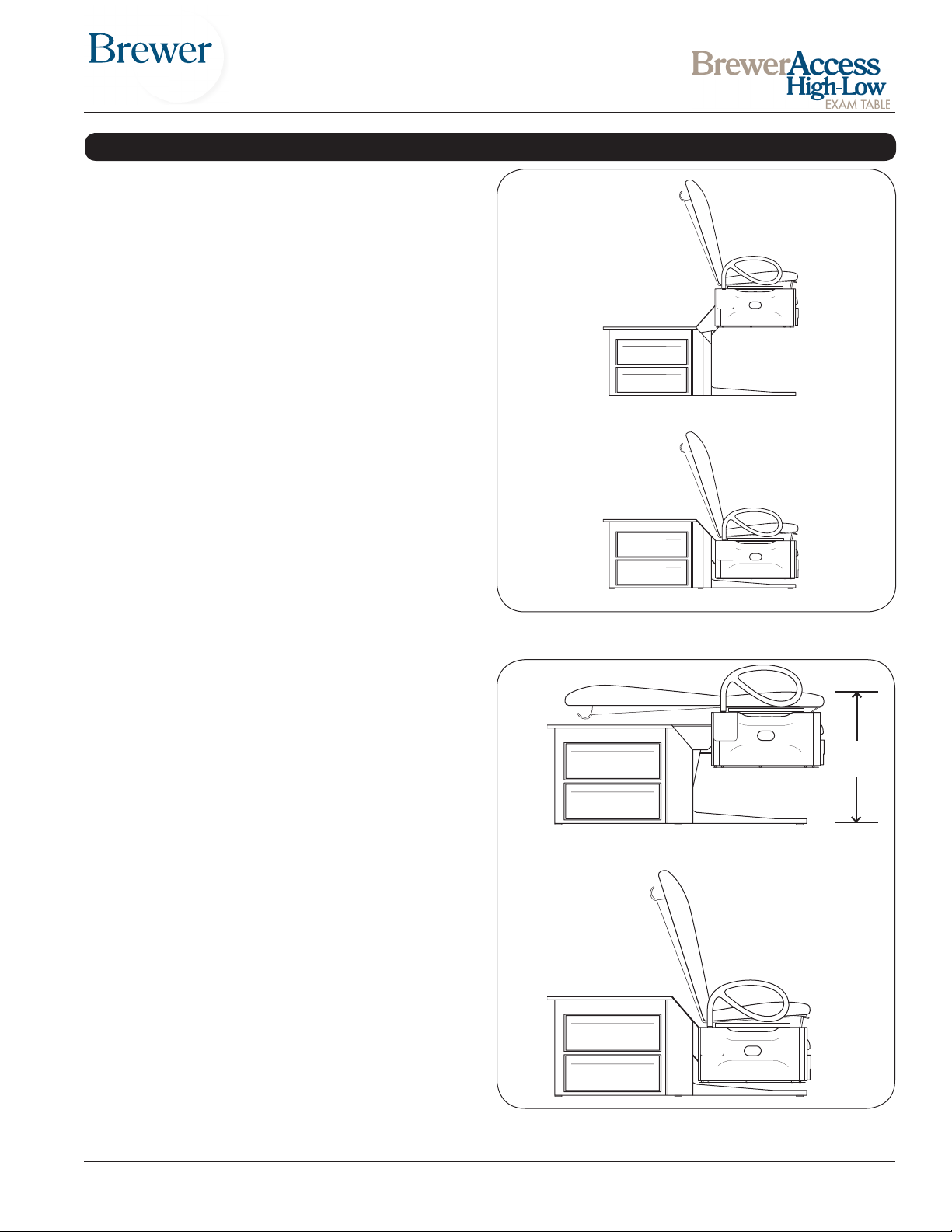
TABLE ADJUSTMENTS
Table Height
The table can be adjusted to any height between 18” to
37” (Figure 27).
1. To raise the table, depress and hold the Table Up
pedal until the desired height is achieved, then release the pedal. (See Figure 12.)
2. To lower the table, raise the backrest to the upright
position, then depress and hold the Table Down pedal
until the desired height is achieved, then release the
pedal. (See Figure 12.)
Seat Back
The back can be adjusted to any angle between horizontal and 80°.
NOTE: The table must be raised to a height of at least
28” before the backrest can be adjusted to the horizontal
position. (See Figure 28.)
Pneumatic Manual Backrest (Models 6000 & 6001)
1. Raise the table to a minimum of 28”
2. To lower the seat back, push down on the seat back
while pulling the release handle upward (See Figure
2).
3. To adjust the back from a horizontal position to a
chair position, press the release handle (located on
either side of the seat cushion) and lift upward. The
seat back will lock in the desired position when the
handle is released.
Powered Backrest (Models 6500, 6501, 6800 & 6801)
1. Raise the table to a minimum of 28” (Figure 28).
2. To adjust the back from an upright (chair) position
to a horizontal position, depress and hold the
Back Down pedal until the desired angle is achieved,
then release the pedal.
3. To adjust the backrest from a horizontal position to
a chair (upright) position, depress and hold the
Back Up pedal until the desired angle is achieved,
then release the pedal.
NOTE: The back is positioned by an actuator that raises
the back when activated. When lowered, the actuator
retracts and gravity causes the back to lower.
Figure 27. Table Height Positioning
28“
Figure 28. Adjusting Seat Back
Document # 100452 RevL 15 Printed in USA © 2013
Page 16
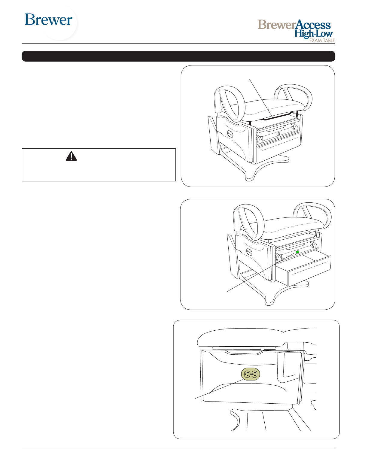
TABLE ADJUSTMENTS (continued)
Manual Pelvic Tilt
(Models 6001, 6501 and 6801)
The manual pelvic tilt feature sets the seat angle at 0°
(horizontal) or 5° (up) position.
Pull up on the front of the seat and the pelvic tilt automatically travels to the locked tilt position (Figure 29).
Note: pulling up with excessive force can damage the
pelvic tilt mechanism. Lift only with enough force to
engage mechanism. Lift the adjustment lever and lower
the seat to the horizontal position.
CAUTION
Patient must be removed from table prior to lowering the seat.
Front Drawer Warmer
(Models 6001, 6501 and 6801)
Models 6001,6501 and 6801 are equipped with a drawer
warmer that is turned on by a switch located above the
drawer (Figure 30).
Pelvic Tilt Adjustment Bar
Figure 29. Pelvic Tilt Adjustment
Note: Do not stack instruments in the front drawer. Place
instruments in one layer in the bottom of the drawer.
Note: This switch is for the drawer warmer only. The
On/Off switch for the table functions is located on the
back of the table (Figure 14).
Outlet
(Models 6001, 6501 and 6801)
Models 6001,6501 and 6801 are equipped with
an Outlet (Figure 31). The total amperage rating
for the table is 3 amps. The maximum total load
that can be plugged into the outlet is 2 amps.
Drawer Warmer
(Models 6001,
6501 and 6801)
Figure 30. Front Drawer Warmer Switch
Caution: Maximum Total Load 3A
Outlet
(Models 6501 and 6801)
(Optional on 6001)
Figure 31. Table Outlet
Document # 100452 RevL 16 Printed in USA © 2013
Page 17
MAINTENANCE
Preventative Maintenance
CAUTION
Failure to perform periodic inspections of the
table could result in personal injury or equipment
damage.
• Periodically inspect the electrical cord to ensure it is
free of cuts or damage.
• Inspect the mechanical functions to ensure satisfactory operation. Complete the operating test.
• Check fasteners to make sure they are present and
tightened securely.
• Lubricate moving parts (such as back and storage
cover hinges) with a food grade silicon lubricant.
• Have a qualied technician inspect your table every 6
months.
Control Box Fuse Replacement
WARNING
Disconnect power by removing plug from the
power outlet before changing fuses.
1. Manually raise table and prop in raised position.
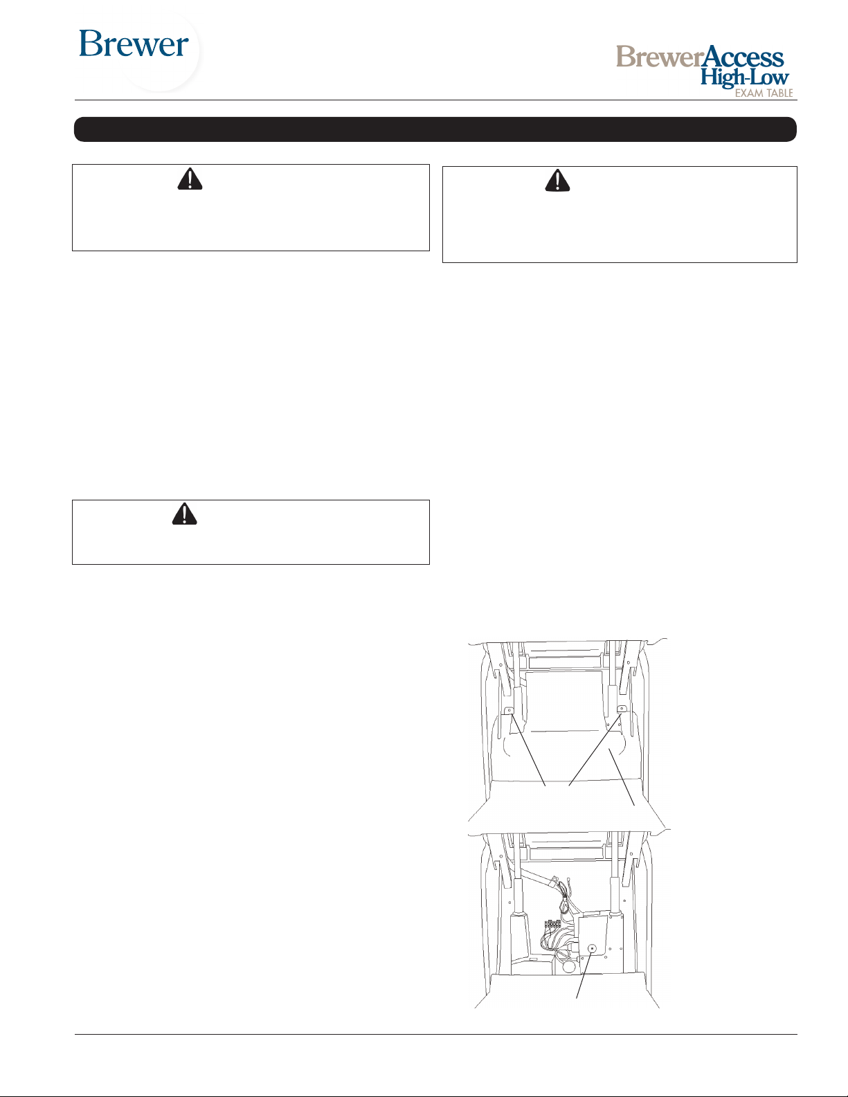
2. Remove shroud below seat to expose actuators and
control box. (See Figure 32.)
Table Care
CAUTION
The upholstery material is resistant to most medicinal type stains, but may be damaged by solvents
and dyes. Remove any spilled uids from the upholstery immediately.
Clean the table weekly, wiping the painted metal and
plastic surfaces with a clean, soft cloth. If desired, mild
cleaners may be used.
Clean the work surface and rear paper storage cover im-
mediately after contact with any uids or gels. Use a mild
soap and rinse with clear water. Avoid the use of harsh
chemicals as they can permanently damage the nish.
Upholstery Removal
1. Remove the two screws under the seat securing the
pelvic tilt lever to the seat frame (models equipped with
pelvic tilt only, all other models skip to step 2).
2. Lift the seat and remove the three screws securing the
hinge to the seat frame.
3. Remove one screw in the paper holder securing the
seat back to the back frame.
4. Remove the upholstery from the table.
5. To remove the leg extension upholstery, pull up on pad
to release the plastic clips.
3. Locate fuse cover on control box. (See Figure 33.)
4. Pull out fuse cover with pliers. Note: pull cover
straight out. Do not twist.
5. Replace fuses using spare fuses in fuse cover. Fuse
type is 250V/2.5AT for 115 VAC and 250V/1.25AT for
230 VAC models.
6. Reassemble.
Remove Two Screws
Remove Cover
Figure 32.
*Drawer Warmer Fuse Replacement
(Models 6001, 6501 and 6801)
1. Remove two fuse covers from back of table near the
power cord.
2. Replace both fuses. Fuse type is 5 x 20mm,
250V/1.0A.
3. Replace fuse covers.
* Models 6001, 6501 and 6801 with Warmer & Outlet
have a single fuse. Fuse type is 5 x 20mm, 250V/3.0A.
Document # 100452 RevL 17 Printed in USA © 2013
Remove Fuse Cover
and Replace Fuses
Figure 33.
Page 18

TROUBLESHOOTING
Operating Test
It is possible to verify normal operation of the
series 6000 tables by performing the following
series of tests.
ALL MODELS
Lift test
1. Insure ON/OFF switch is in ON position.
2. Press and hold the TABLE UP pedal. The
table should rise to the full up position
(about 37”) and stop. There must be no
continuing motor hum after the table stops.
3. Release the TABLE UP pedal.
4. Press the TABLE DOWN pedal. While
the table is going down pressing on each
corner of the back of the seat must cause
the table to momentarily stop.
5. The table should go to the full down posi tion. Release the TABLE DOWN
pedal.
6. Reach under the front section bottom plate
and lift up momentarily on each corner of
the plate. This should activate the lift caus ing the table to rise while the plate is lifted.
7. Turn the ON/OFF switch, located on the
back of the rear cabinet, to the OFF posi tion. Verify that pressing any of the foot
pedals does not cause motion. Turn the
ON/OFF switch to the ON position.
MODELS 6500, 6501, 6800 and 6801 ONLY
Powered Back test
1. Press the TABLE UP pedal to raise the table
above 28” so the back may be lowered without
contacting the back cabinet.
2. Press the BACK DOWN pedal. The back
should go to the full recline position, which is
level.
3. Press the BACK UP pedal. The back should
go to the full up position.
4. Press the BACK DOWN pedal. While the
back is going down pressing on any corner of
the back of the seat must cause the back to
momentarily stop.
5. Press the blue RETURN TO CHAIR button on
the foot control. While the chair is in motion
momentarily press the red STOP button. The
chair must stop and remain stopped.
6. Press the blue RETURN TO CHAIR button on
the foot control. While the chair is in motion
momentarily press the BACK UP pedal. The
chair must stop and remain stopped.
7. Press the blue RETURN TO CHAIR button on
the foot control. While the chair is in motion
momentarily press the BACK DOWN pedal.
The chair must stop and remain stopped.
8. Press the blue RETURN TO CHAIR button
on the foot control. While the chair is in mo tion momentarily press the TABLE UP pedal.
The chair must stop and remain stopped.
9. Press the blue RETURN TO CHAIR button on
the foot control. While the chair is in motion
momentarily press the TABLE DOWN pedal.
The chair must stop and remain stopped.
10. Raise the table to the full up position, and then
lower the back so the table is in the high table
position. Press the blue RETURN TO CHAIR
button. The table should rst raise the back
then lower to the chair low position.
Document # 100452 RevL 18 Printed in USA © 2013
Page 19
Step #
of 6 is not closing when pressed.
released. Replace as necessary.
Start Here
No movement
Some
movement
Go to step 2.1
Go to step 2.2
properly? Does outlet work?
Yes or N/A
No
assistance.
Fixed
Still bad
released. Replace as necessary.
Fixed
Yes
No
Return to step 1
Control box is over temperature.
Control box resets automatically.
Yes
No
No
Yes
identified?
Go to step 5.1 for Heater
Go to step 7.1
Table stops after period of heavy
Still bad
Do all powered functions work?
Yes
No
work properly?
Yes
No
Do the 4 seat back limit switches
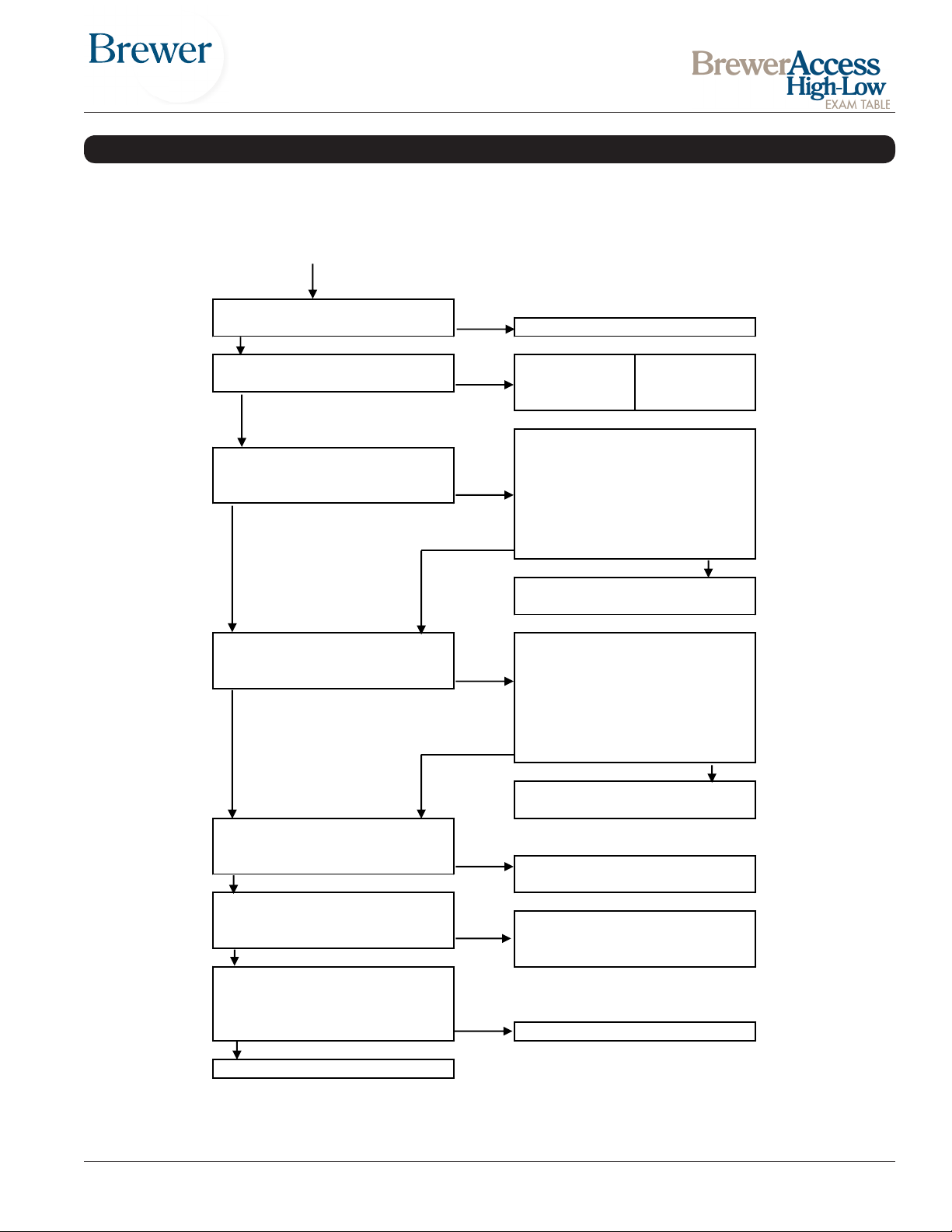
6000 SERIES TABLE TROUBLESHOOTING CHART
1
2
3
4
Complete the operational test
Test fails Test passes Test Complete
Do the 6 front limit switches
work properly?
Front cabinet switches; 1 or more
Press each one and listen for click
when pressed and again when
Call 1 888-Brewer1 for technical
assistance.
Seat back switches; 1 or more of 4
is not opening when pressed.
Press each one and listen for click
when pressed and again when
Does the drawer warmer heat
5
use. *see below
6
Is there excessive noise or other
problems which are not yet
7
* No relay clicking in control box. Table then functions after about 30 minutes.
Document # 100452 RevL 19 Printed in USA © 2013
Call 1 888-Brewer1 for technical
Go to step 6.1 for Outlet
Allow 30 minute cool down.
Page 20
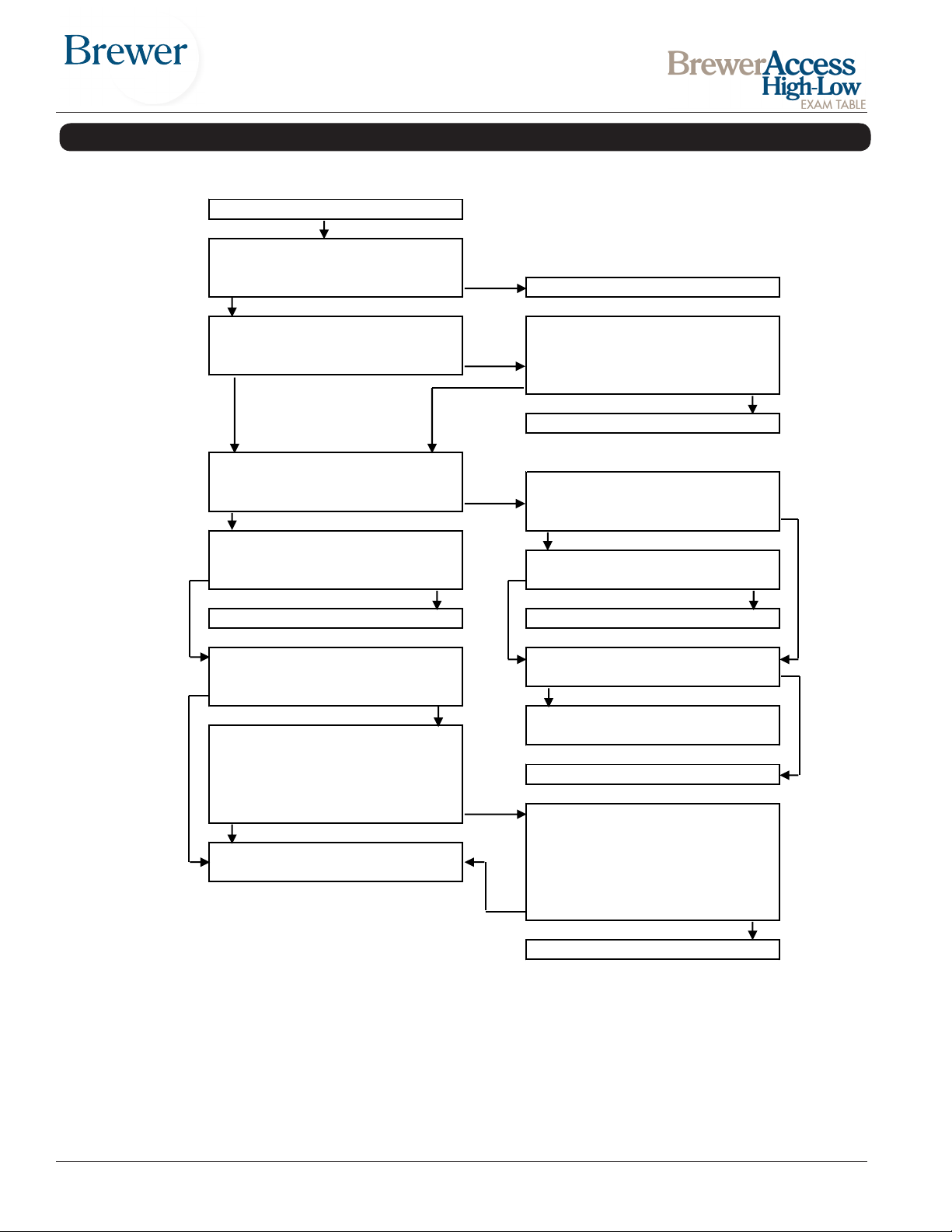
2.1
Return to step 1
Step 2.1 continue here
assistance.
or repair.
control box?
position?
lifted there is no relay click.
Call 1 888-Brewer1 for technical
Return to step 1
Return to step 1
at terminal block.
Return to step 1
Return to step 1
illuminated when turned on?
Still bad
Fixed
Press foot control pedal. Does
Replace 2 control box fuses.
Still bad
Is on/off switch on back of cabinet
Yes
No
Yes
No
Fixed
Still bad
Fixed
Ok
Turn on switch, then return to step 1
Fixed
6000 SERIES TABLE TROUBLESHOOTING CHART (continued)
a
b
c
d
e
f
turned on?
If table has a heater, is the switch
Yes
relay in control box click?
Check for loose wire connections
Is the table stuck in the up
No
No heater or No
Yes
Check for loose plug in wall outlet
or back of table. Check for power
at outlet.
Is green light on at back side of
No Yes
Replace control box.
Table does not go down. Control
box relay clicks in down direction.
g
Document # 100452 RevL 20 Printed in USA © 2013
When front bottom switch plate is
No Yes
Call 1 888-Brewer1 for technical
assistance.
Front cabinet switch (one of 6) is
stuck on. (closed) Unplug table
power. Isolate faulty switch or wire
using a continuity tester. Replace
Still bad Fixed
Page 21
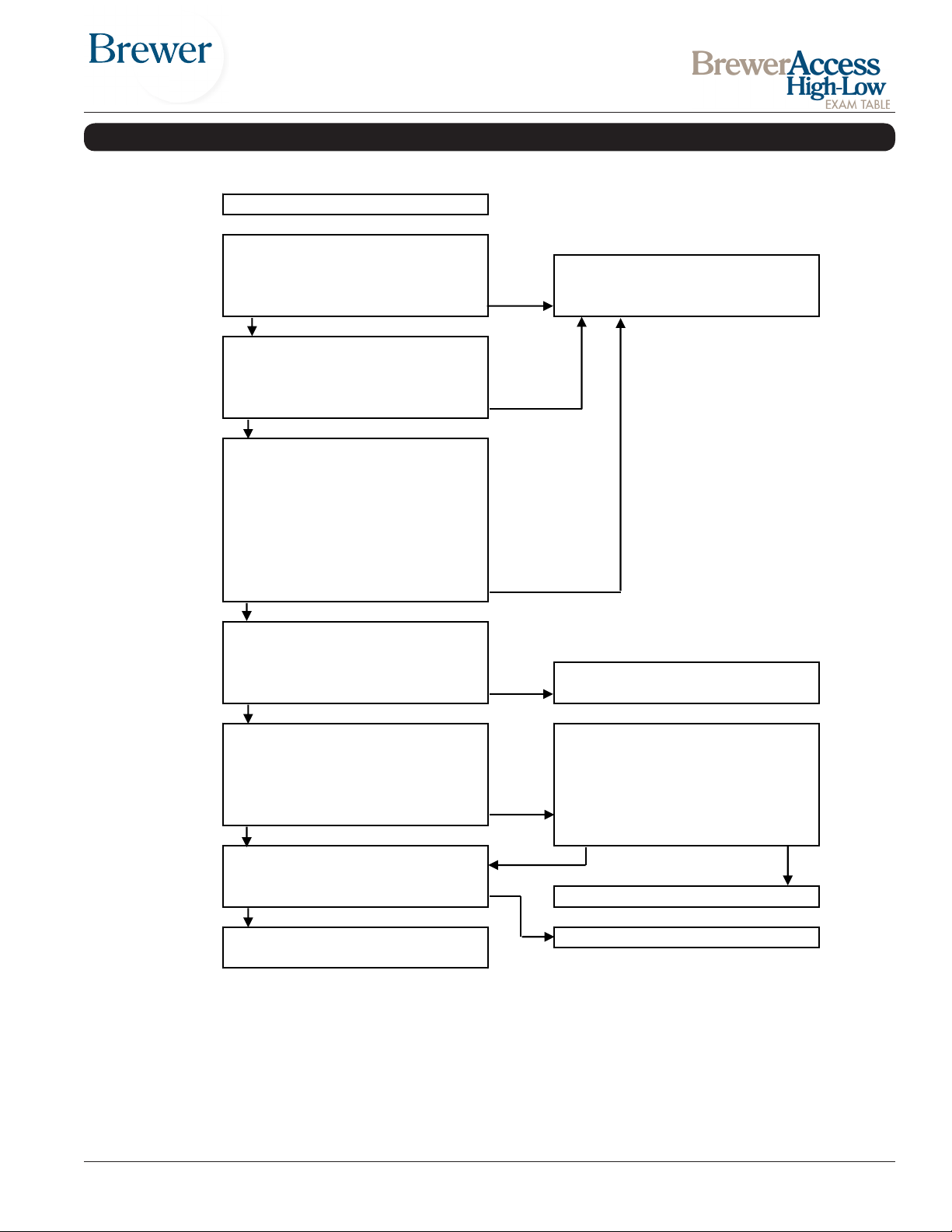
2.2
Yes
No
No
Yes
No
Yes
No
Yes
of 4 is not closing when pressed.
released. Replace as necessary.
Replace back actuator.
No
Yes
One lift actuator has failed.
to step 1.
Retun to step 1.
Step 2.2 continue here
assistance.
No problem found, test complete.
pressed.
Return to step 1
Still bad
Fixed
down direction.
No
Yes
6000 SERIES TABLE TROUBLESHOOTING CHART (continued)
Table raises slightly slower than
normal while the up pedal is held.
a
One actuator continues to hum.
Table is low and does not rise, but
motors hum when up pedal is
b
Table does not go all the way
down. After table stops in the down
direction, continue pressing the
down pedal. One actuator
c
continues to hum for a few seconds
while there is no movement.
Replace both lift actuators. Return
No backrest movement. Motor
hums in the up direction but there
d
is no movement.
Backrest or table lift stuck in full up
Backrest safety switch, 1 or more
position. No motor hum. Control
box relay clicks in both up and
e
Press each one and listen for click
when pressed and again when
Are there other problems not yet
f
identified?
Call 1 888-Brewer1 for technical
Document # 100452 RevL 21 Printed in USA © 2013
Page 22
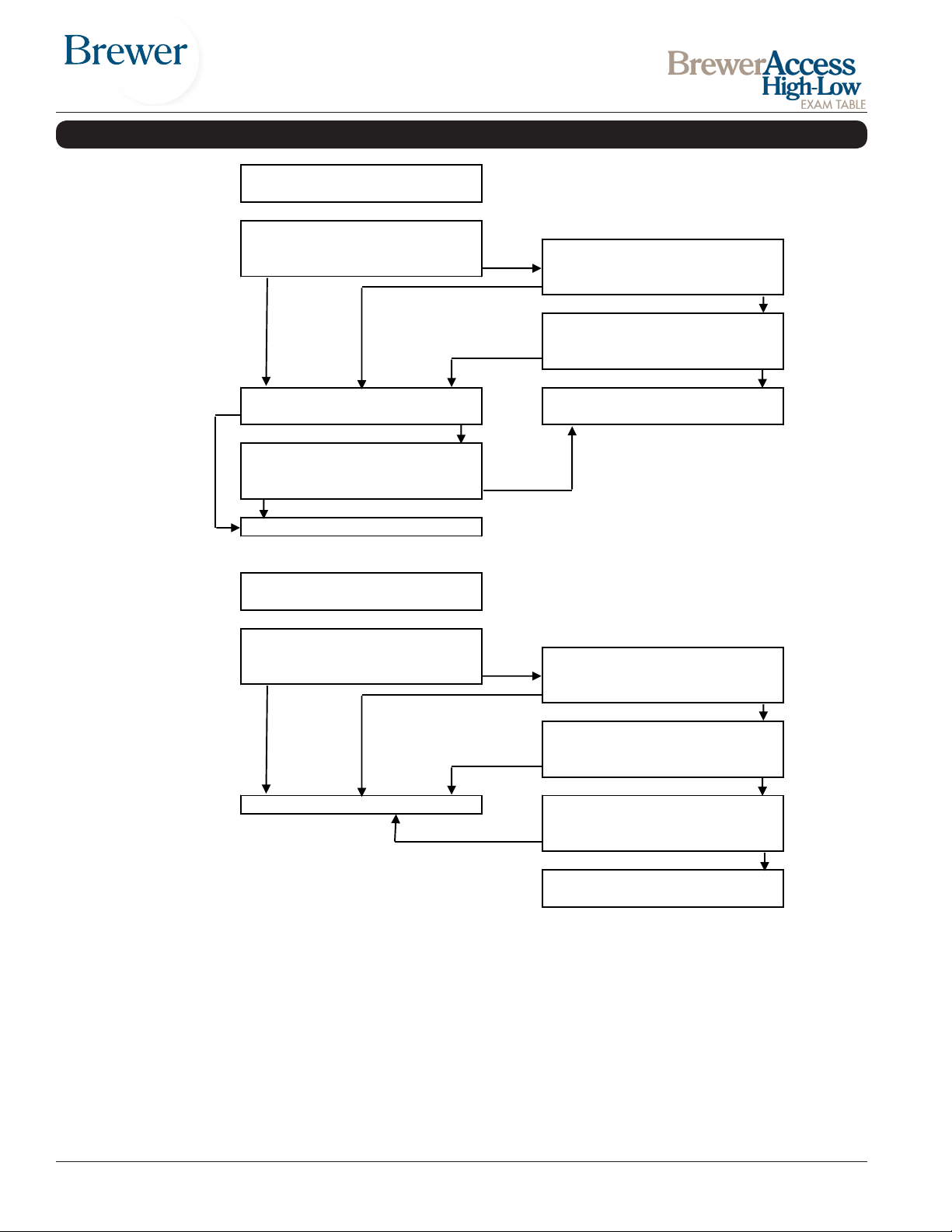
5.1
6.1
Does outlet work now?
Yes
No
Yes or N/A
Replace transformer.
No
Replace table outlet.
Does outlet work now?
Yes
No
Return to step 1
No
Does outlet work now now?
Yes
Yes
No
Step 6.1 continue here
Yes
No
Replace heater.
Does heater get warm now?
Yes
No
Replace heater switch.
Does switch illuminate now?
Drawer warmer
Step 5.1
Replace heater fuse(s).
YesNoDoes switch illuminate now?
6000 SERIES TABLE TROUBLESHOOTING CHART (continued)
continue here
a
b
c
a
Heater switch illuminates when on.
Yes No
Heater gets warm when on. Call 1 888-Brewer1 for technical
assistance.
Return to step 1
Outlet Option
Device works when plugged in to
table outlet.
Replace heater / outlet fuse.
Document # 100452 RevL 22 Printed in USA © 2013
b
c
Call 1 888-Brewer1 for technical
assistance.
Page 23
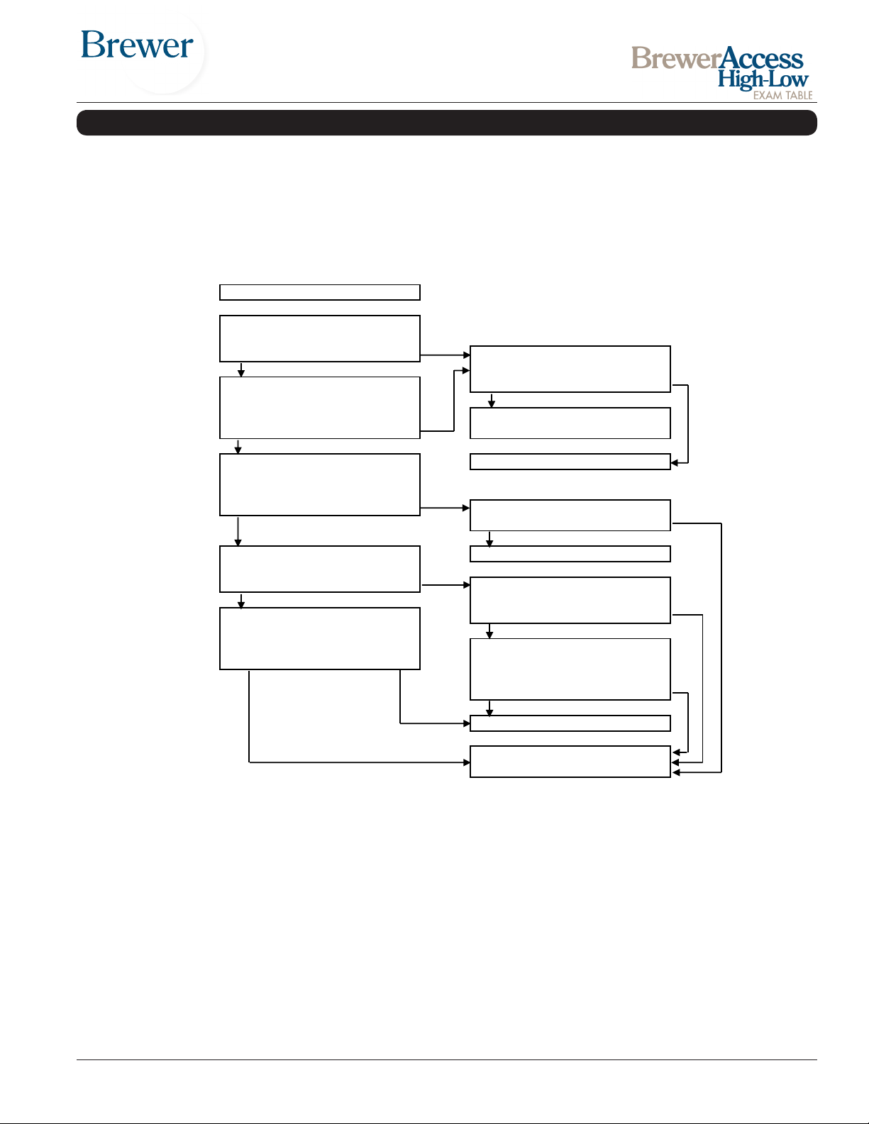
7.1
a
b
Fixed
Fixed
Still bad
Return to step 1
Call 1 888-Brewer1 for technical
assistance.
Backrest raises but seat does not
lower.
Return to step 1
Yes
No
simultaneously.
Still bad
No movement at all, or movement
foot pedals.
Return to step 1
No
Yes
Replace foot control
Are there other problems not yet
resolved?
Yes
No
Step 7.1 continue here
Yes
No
6000 SERIES TABLE TROUBLESHOOTING CHART (continued)
Does table have a powered
backrest?
Does table return to chair position
when blue button is pressed on foot
control?
is not stopped by stop button or
c
Call 1 888-Brewer1 for technical
assistance.No Yes
Fixed Still bad
d
backrest and seat operate
Backrest actuator limit switch is not
being actuated. Repair or replace
e
switch.
Yes No
Backrest actuator limit switch has
failed. Repair or replace the switch.
Document # 100452 RevL 23 Printed in USA © 2013
Page 24
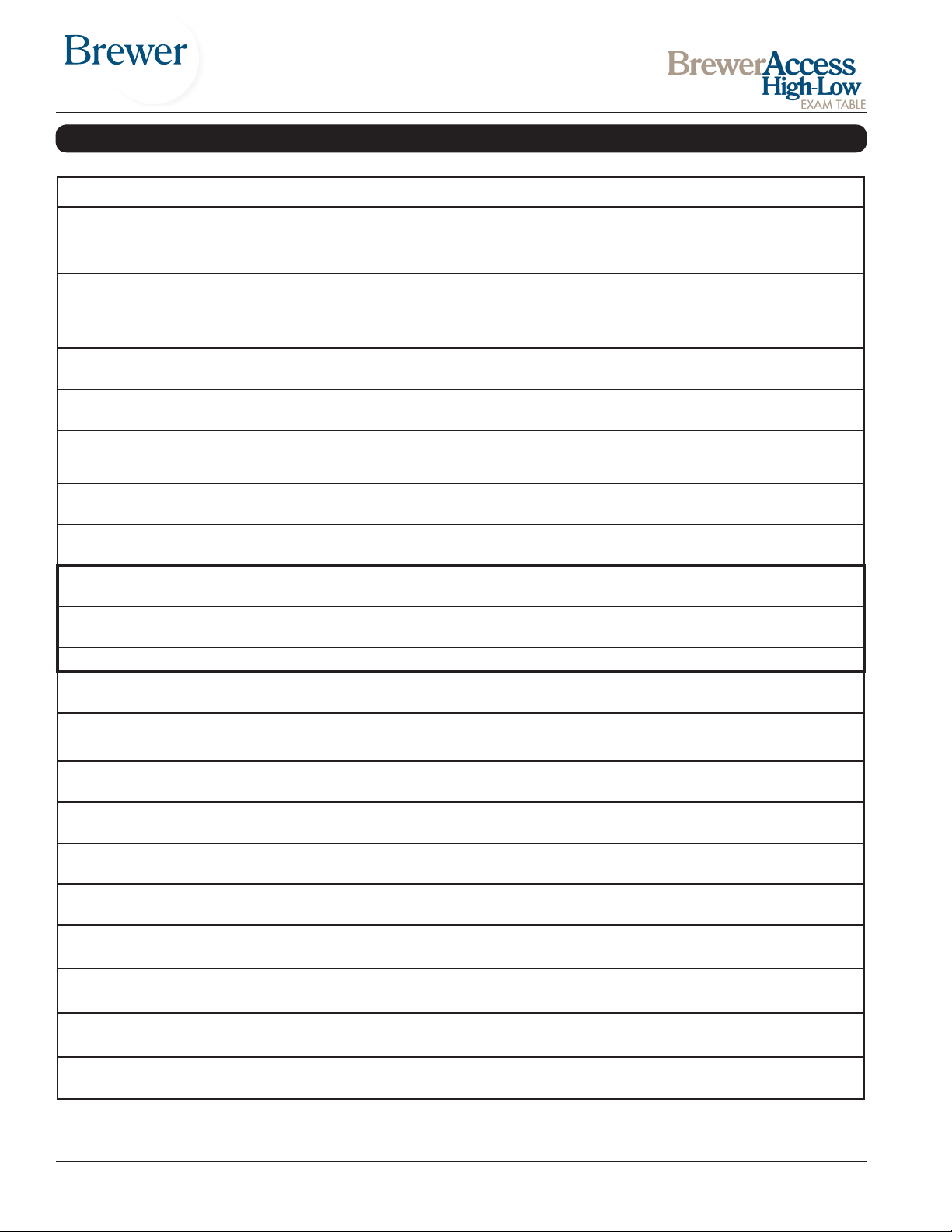
OPTIONS, ACCESSORIES, AND COMMON SERVICE PARTS
Listed below are the accessories which are authorized for use with this table.
Description Order No. Use/Restrictions
Intended Use - Replacement top with hardware for 6000,
Replacement Upholstery 6115-XX
Special Upholstery 6115-SP
Urology Tray w/Hose & Bucket 100253
Front Drawer Organizer 100407
6001, 6500, 6501,6800 and 6801 examination tables in
15 standard and 5 plush colors. Includes pelvic tilt bar.
Intended Use-Allows the purchase of specialty vinyls in
different colors with hardware for the model 6000, 6001,
6500, 6501, 6800 and 6801 examination table. (Additional charges may apply.) Includes pelvic tilt bar.
Intended Use - Conveniently and safely disposes of and
captures uids during urology procedures.
Intended Use - Optional front drawer dividers for separation and organization.
Replacement Leg Support Pad 100267
Replacement Leg Extension Pad 2102036
Stainless Steel Treatment Pan 98464
Deluxe Articulating Knee Crutches 99504
Knee Crutch Adapters (eld install) 100550
Knee Crutch Clamp 100187 Intended Use - To hold deluxe articulated crutches.
Fuse 1A 100777
Fuse 3A 100088
Electrical Outlet
(6001 only- factory installed)
Welch Allyn III Light Bracket
(factory installed)
Welch Allyn III Light Bracket
(customer installed)
Welch Allyn IV Light Bracket
(factory installed)
Welch Allyn IV Light Bracket
(customer installed)
101800
100880 Intended Use - For mounting of Welch Allyn III light
100881 Intended Use - For mounting of Welch Allyn III light
102031 Intended Use - For mounting of Welch Allyn IV light
102032 Intended Use - For mounting of Welch Allyn IV light
Intended Use - Replacement upholstered leg support
pad
Intended Use - Replacement upholstered leg extension
pad
Intended Use - Stainless Steel Treatment Pan replacement
Intended Use - Allows leg positioning for ease of examination.
Intended Use - Provides attachment point for Knee
Crutch Clamps.
Intended Use - 1A drawer warmer replacement fuse (qty.
2)
Intended Use - 3A drawer warmer / outlet replacement
fuse (qty. 1)
Intended Use - Outlet provides power for medical accessories.
Armrest Hole Cap 101872
Foot Control, (Two-pedal with Return-ToChair feature 6500, 6501, 6800 & 6801)
Foot Control (Single-pedal for manual
back models 6000 and 6001)
Document # 100452 RevL 24 Printed in USA © 2013
100761 (hard wired)
101375 (detachable)
100763 (hard wired)
101376 (detachable)
Intended Use-Covers hole created when user chooses to
remove table arms.
Intended Use-Direct replacement for a 2-pedal foot control with return to chair feature only.
Intended Use-Direct replacement for a single-pedal foot
control.
Page 25
LIMITED WARRANTY
The Brewer Company
GENERAL TERMS AND CONDITIONS
Warranty: The Brewer Company warrants its AssistPRO Programmable Table, Assist Power Procedure Table, Access High-Low Exam Table,
Basic Exam Table, Element Treatment Table, and LiftMate™to be free from defects in parts and workmanship under normal use and service for
a period of three (3) years from date of shipment. The Brewer Company warrants its Access Exam Table, seating products, and support products
to be free from defects in parts and workmanship under normal use and service for a period of ve (5) years from date of shipment. The Brewer
Company warrants its lighting products to be free from defects in parts and workmanship under normal use and service for a period of one (1)
year from date of shipment.
The Brewer Company will not be responsible for any Product failure due to abuse, misuse, modication or improper use or for any use which exceeds the published capacity of the Product. THIS WARRANTY IS EXCLUSIVE AND IN LIEU OF ALL OTHER WARRANTIES AND REMEDIES
WHATSOEVER, INCLUDING BUT NOT LIMITED TO IMPLIED WARRANTIES OF MERCHANTABILITY AND/OR FITNESS FOR A PARTICULAR
PURPOSE. NO AGENT, EMPLOYEE, OR REPRESENTATIVE OF THE BREWER COMPANY HAS ANY AUTHORITY TO MAKE ANY AFFIRMATION, REPRESENTATION, OR WARRANTY NOT SET FORTH IN THESE TERMS AND CONDITIONS CONCERNING ANY PRODUCTS OF
THE BREWER COMPANY. THE BREWER COMPANY SHALL HAVE NO LIABILITY WHATSOEVER FOR DAMAGES CAUSED BY TRANS-
PORTATION, ACCIDENTS, FIRE, UNAUTHORIZED ALTERATION, OR NORMAL WEAR OR ABUSE, NOR SHALL THE BREWER COMPANY
HAVE ANY LIABILITY WHATSOEVER FOR ANY INCIDENTAL OR CONSEQUENTIAL DAMAGES, including without limitation, lost prots or any
such damages arising from (a) the design, manufacture, sale, delivery, installation, repair, operation or use of products of The Brewer Company
or any part there of, (b) any actual or alleged failure or defect in products of The Brewer Company or any part thereof, or (c) any actual or alleged
breach or non-performance by The Brewer Company of this limited warranty.
Freight Claims: Upon receipt, merchandise should be carefully examined to ascertain that proper amount has been received in good condition.
Any claim for shortage or damage must be made with delivering carrier within ve (5) days from receipt of goods. Brewer does not assume any
responsibility for loss or damage in transit, and compensation for such loss must be obtained from the freight carrier.
Obtaining warranty service: Warranty service must be obtained through The Brewer Company by contacting Customer Service by phone at
1.888.Brewer.1, by fax at 1-262-251-1786 or by e-mail at [email protected]. If the product is within the warranty period
described above, Brewer will either provide on-site repair services, ship replacement parts or replace the product at the discretion of The Brewer
Company. On-site service is provided only within the Continental United States, and only replacement parts or product will be provided at
Brewer’s discretion in Alaska, Hawaii, Canada and all other International locations. A product warranty registration must be completed for exam
tables and LiftMates and submitted to Brewer within 30 days after purchase in order to receive warranty benets. Warranty cards are included in
the purchase of all exam tables and LiftMates and are also available online at www.brewercompany.com.
Document # 100452 RevL 25 Printed in USA © 2013
Page 26

NOTES
Document # 100452 RevL 26 Printed in USA © 2013
 Loading...