

Page 1
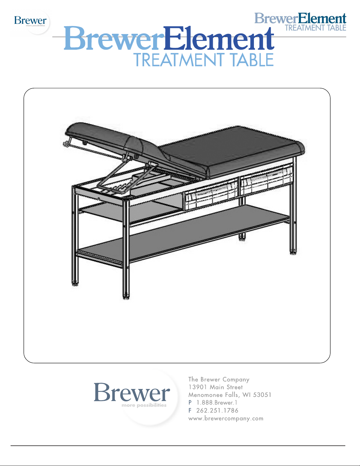
Models 2230 and 2240
Overview ............................................................... 2
Tools Needed.......................................................... 2
Hardware................................................................3
Assembly........................................................... 4-13
Installation............................................................ 14
Document 101294 RevA
Document 101294 RevA
Drawer Removal ................................................. 15
Operation ........................................................... 15
Maintenance ...................................................... 15
Accessories ....................................................... 16
Limited Warranty ................................................ 16
1
Printed in USA © 2010
Printed in USA © 2010
Page 2
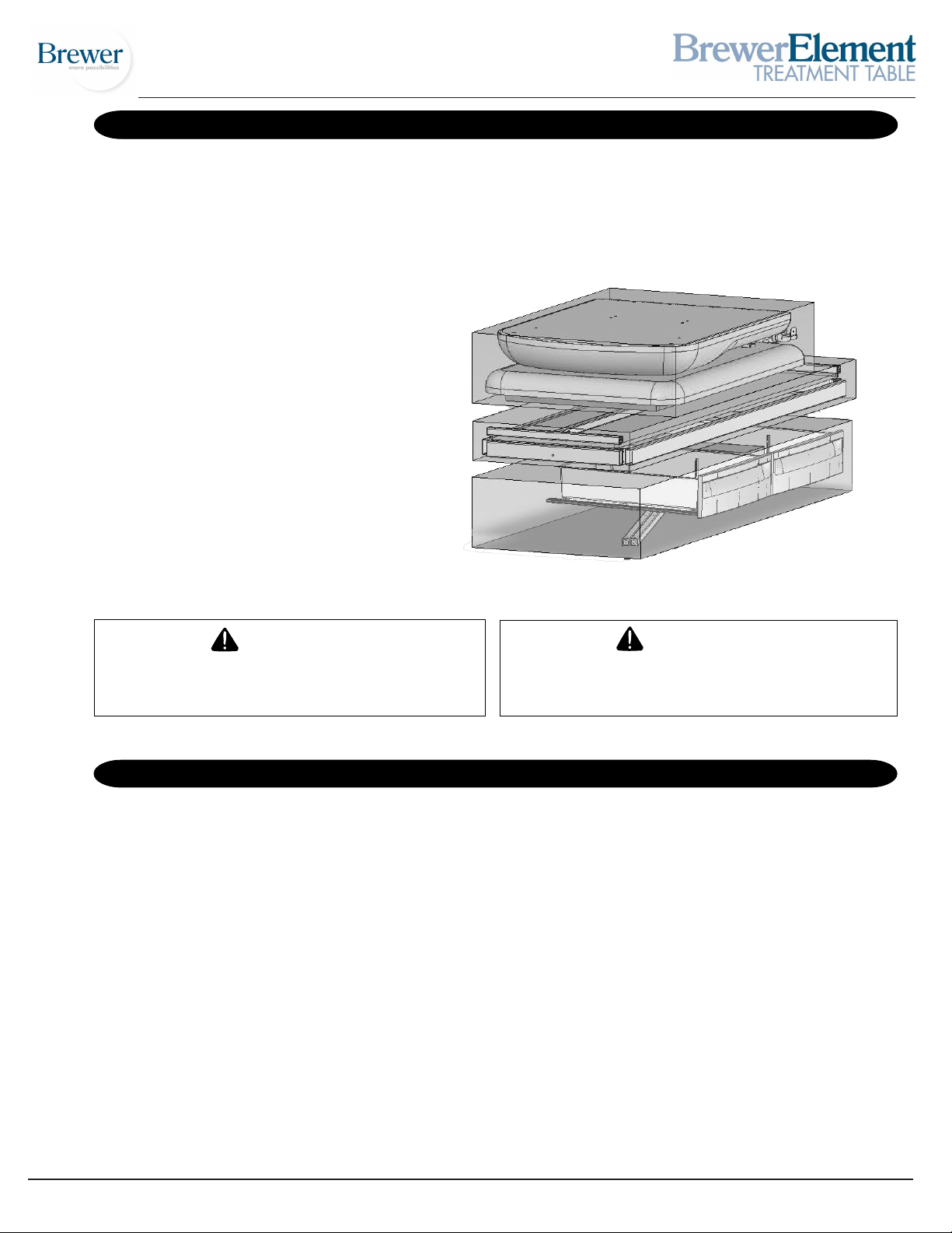
COMPONENT IDENTIFICATION
OVERVIEW
Perform the following sequence in order when setting up
the table:
- Unpacking
- Assembly
- Leveling the Table
- Installing the Paper Roll
MODELS 2230 & 2240
For the above models you will receive
three separate cartons: a frame & shelf
carton, an upholstery carton, and a
drawer carton. Inspect all three
carefully for shipping incurred damage.
NOTE: Save all packaging in case re-shipment is required.
NOTE: Inspect all boxes and contents for damage.
Report any damage to the carrier immediately.
CAUTION
To avoid damaging the table’s upholstery or
painted surfaces, DO NOT use a knife or any other
sharp object to open the packaging.
MODELS 2230 and 2240 TOOLS NEEDED
Rubber Mallet
9/16” Open End Wrench
Phillips Screw Driver
7/16“ , 11/32” Socket or Wrench
WARNING
Two or more people should assist in moving the table.
Use proper lifting techniques when lifting. Failure to
do so could result in serious injury!
Document 101294 RevA
2
Printed in USA © 2010
Page 3
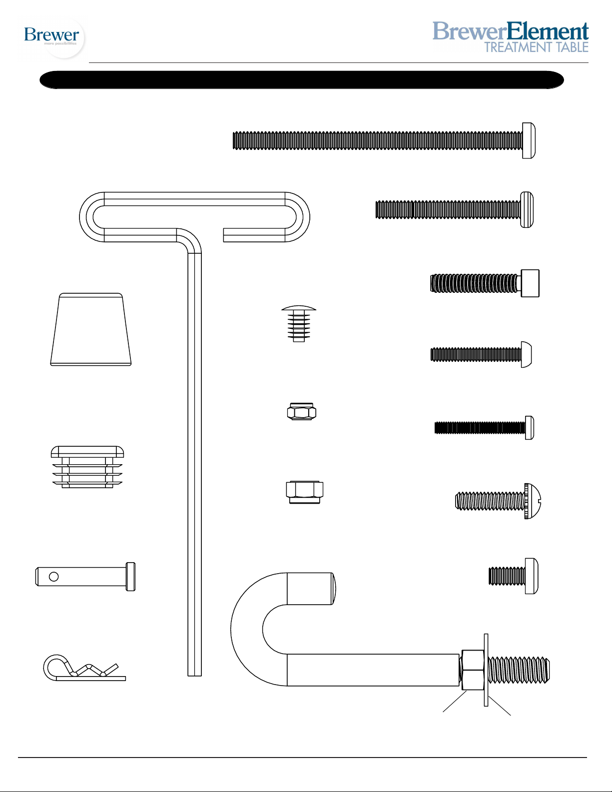
MODELS 2230 and 2240 HARDWARE
Allen Wrench (Qty. 1)
1/4”-20 x 4” Screw A (Qty. 1)
1/4”-20 x 2” Screw B (Qty. 11)
1/4”-20 x 1 1/4” Screw C (Qty. 8)
Snap Rivet (Qty. 32)
Bumper (Qty. 2)
Cap (Qty. 2)
Clevis Pin (Qty. 2)
10-24 x 1 1/4” Screw D (Qty. 2)
8-32 Nut K (Qty. 8)
8-32 x 1 1/4” Screw E (Qty. 8)
1/4”-20 Nut H (Qty. 6)
1/4”-20 x 1” Screw F (Qty. 8)
1/4”-20 x 1/2” Screw G (Qty. 5)
J-Bolt R (Qty. 2)
Cotter Pin (Qty. 2)
Document 101294 RevA
3/8” Nut L (Qty. 2)
3
Washer M (Qty. 2)
Printed in USA © 2010
Page 4
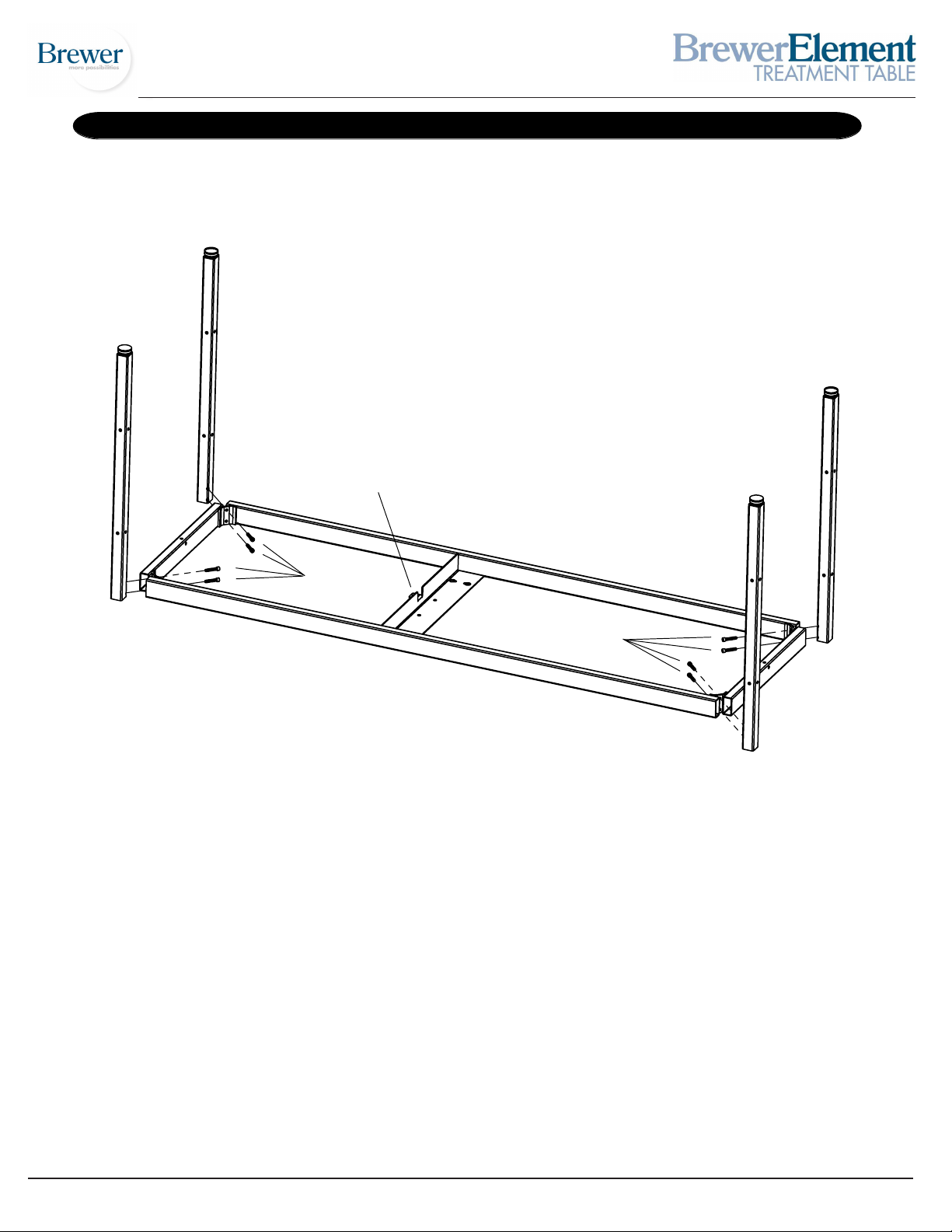
MODELS 2230 and 2240 STEP 1
Notch
Screw C
Screw C
STEP A: Start with table frame inverted: note the position of the Notch in the drawing above is facing
upwards.
STEP B: Positon legs (see drawing above). Insert Screws C (1/4”-20 x 1 1/4”) and snug up by hand only at
this time.
Document 101294 RevA
4
Printed in USA © 2010
Page 5
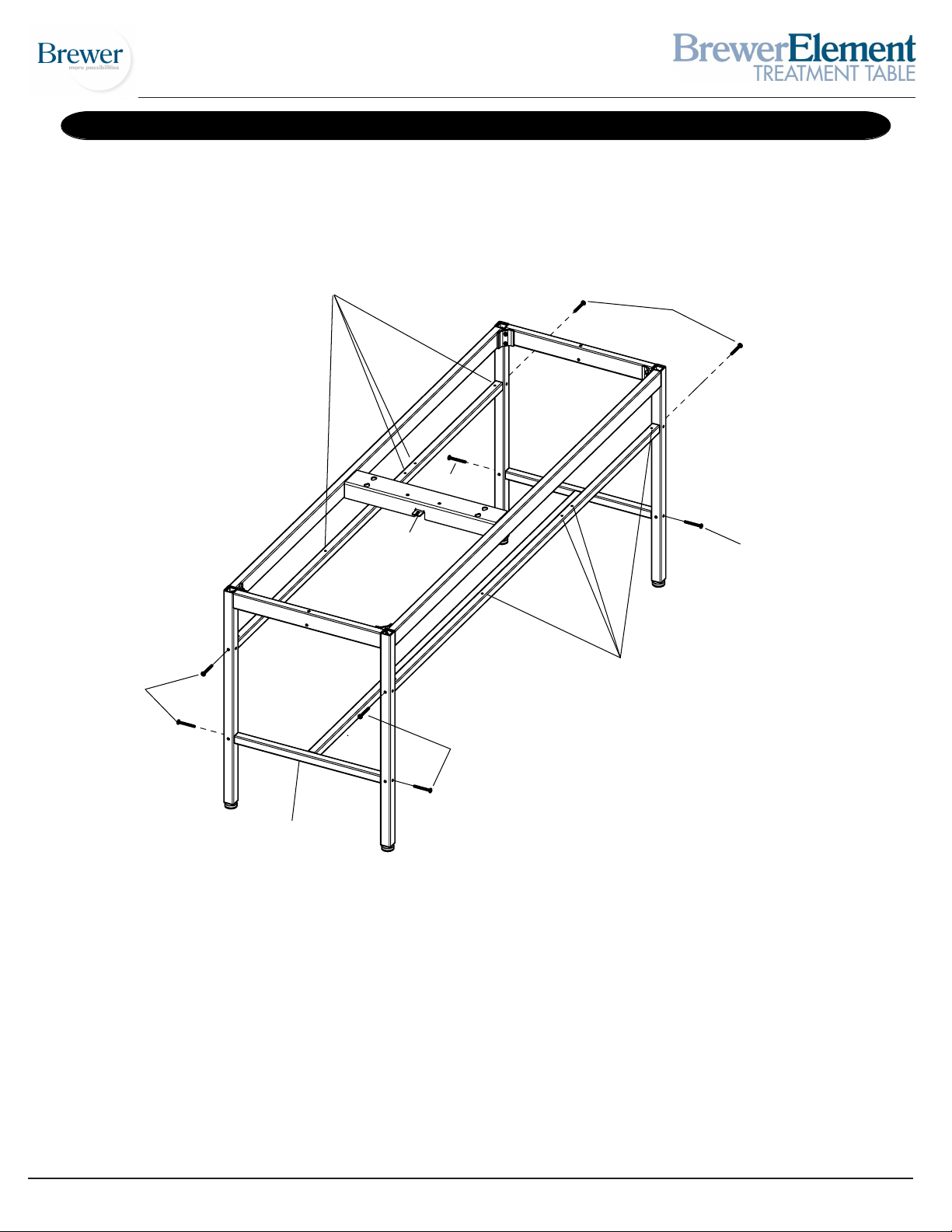
MODEL 2230 and 2240 STEP 2
Drawer Supports
with holes upward and
toward Foot End
Screw B
Foot End
Screw B
Tab
Screw B
Drawer Supports
Screw B
with holes upward and
toward Foot End
Screw B
Shelf Support
STEP A: With table in the upright position install Shelf Support using 4 Screws B (1/4”-20 x 2”). Do not
tighten at this time.
STEP B: Locate Drawer Supports according to above drawing so that the holes through the tube are
facing up, and the holes nearest the ends of the tubes are at the Foot End of the table. Install using 4
Screws B (1/4”-20 x 2”). Do not tighten at this time.
Document 101294 RevA
5
Printed in USA © 2010
Page 6
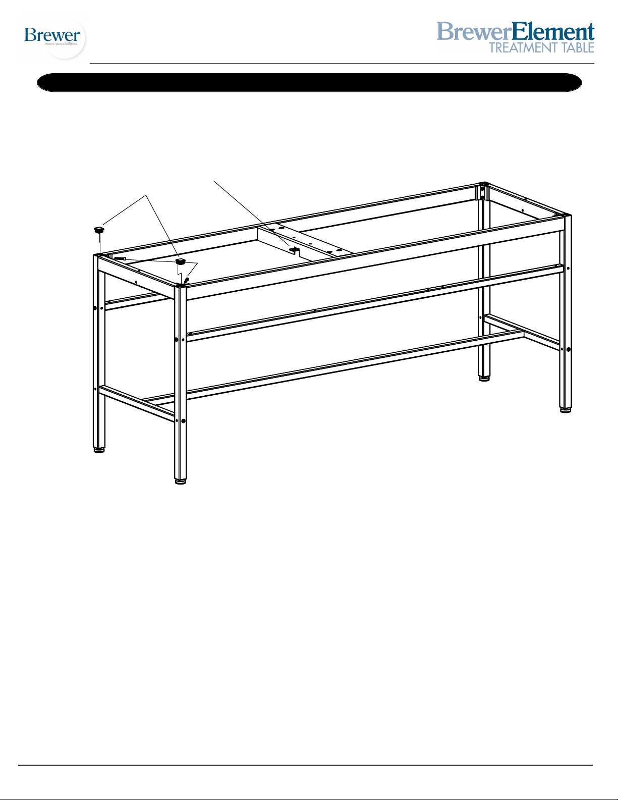
Head End
MODELS 2230 and 2240 STEP 3
Tab
Caps
Upper Leg Screws
STEP A: Remove 2 Upper Leg Screws at Head End of the table, one on each of the two legs. (See illustration above.)
STEP B: Insert Caps into two leg tops and seat with a rubber mallet.
STEP C: Install Upper Leg Screws. Do not tighten at this time.
Document 101294 RevA
6
Printed in USA © 2010
Page 7
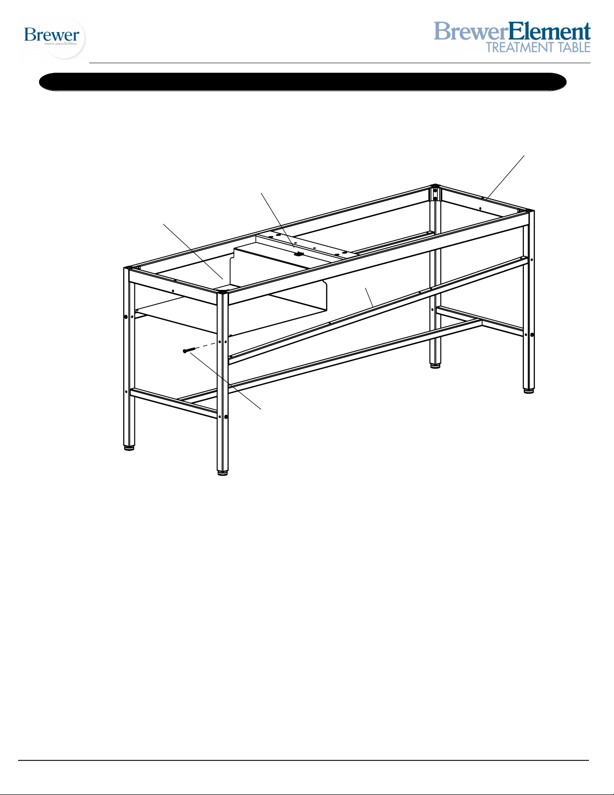
Head End
MODELS 2230 and 2240 STEP 4
Top Rail
Tab
Paper Shelf
Drawer Support
Remove this Screw
Only
STEP A: Remove one Drawer Support screw from the Head End of the table as shown.
STEP B: Insert Paper Shelf between the Top Rail and the loose Drawer Support. Make sure the Paper Shelf
is mounted below the Tab as shown.
STEP C: Reinstall the Drawer Support and its corresponding screw. Do not tighten at this time.
Document 101294 RevA
7
Printed in USA © 2010
Page 8
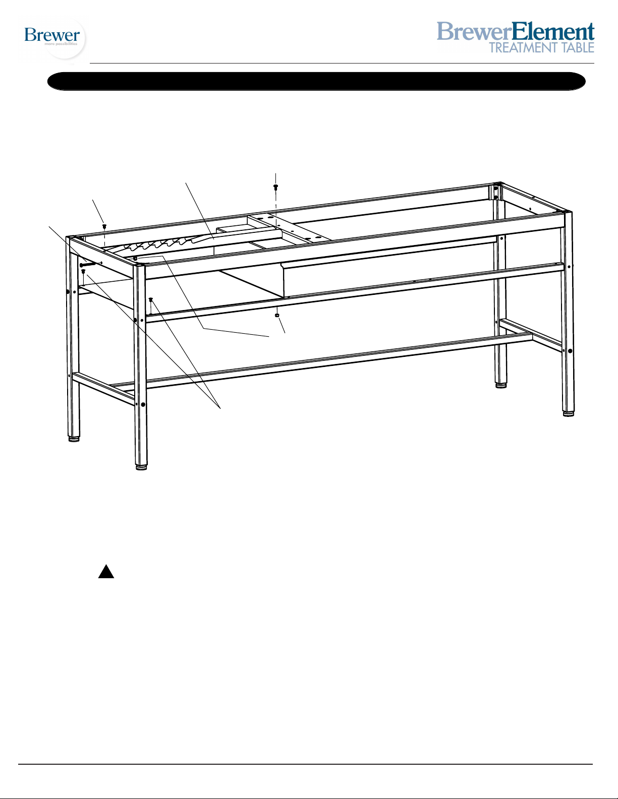
MODELS 2230 and 2240 STEP 5
Snap Rivet
Screw B
Backrest Catch
Screw G
Paper Shelf
Nut H
Snap Rivets
STEP A: Install Backrest Catch as shown in the drawing above.
CAUTION ! The Backrest Catch needs to be positioned on top of the Tab shown in STEP 4.
STEP B: Install Screw B (1/4”-20 x 2”) through frame rail and into Backrest Catch and tighten Nut H
(1/4”-20). Insert Screw G (1/4”-20 x 1/2”) through Backrest Catch and Tab. Tighten Nut H onto Screw G.
STEP C: Install 3 Snap Rivets.
Document 101294 RevA
8
Printed in USA © 2010
Page 9
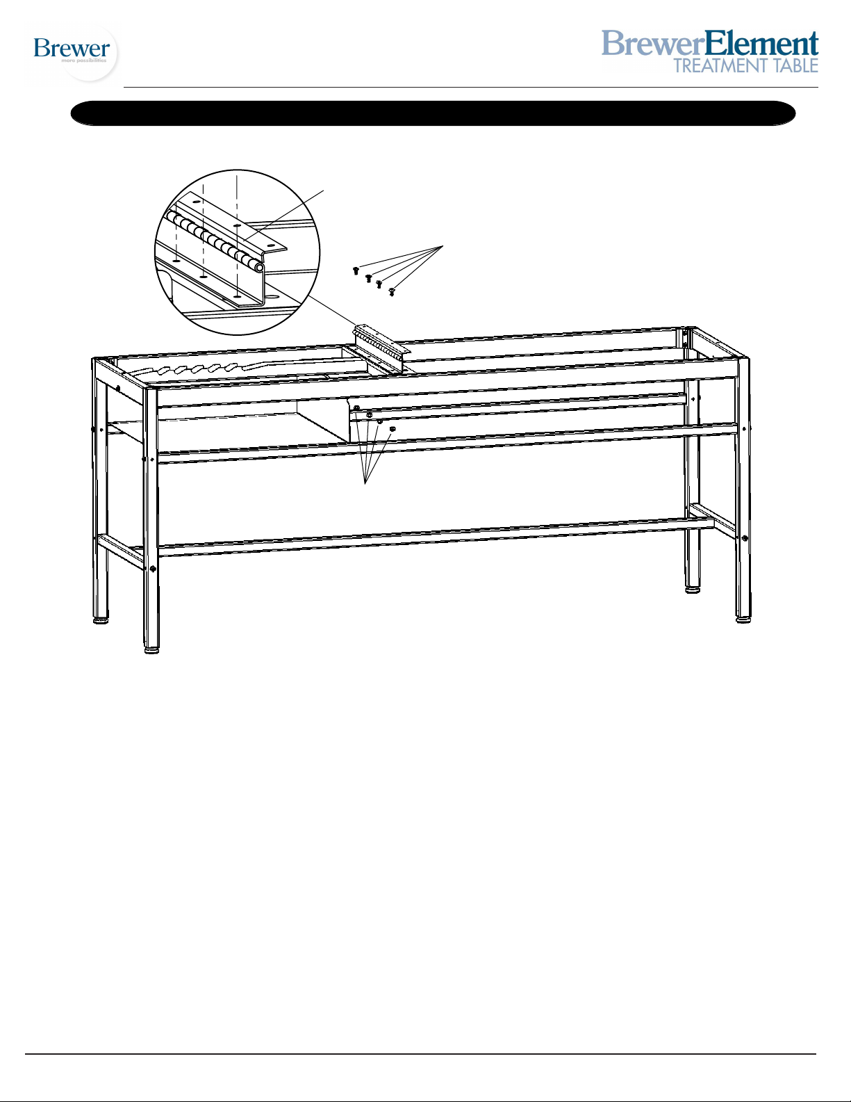
Head End
MODELS 2230 and 2240 STEP 6
Detail of Hinge
Assembly
Screw G
Nut H
STEP A: Align holes in Hinge with holes in frame. Hinge must be oriented as shown with Hinge mounting
flange facing the Head End of the table.
STEP B: Install 4 Screws G (1/4”-20 x 1/2”) into the Hinge and through the frame. Fasten with
4 Nuts H (1/4”-20) and tighten.
Document 101294 RevA
9
Printed in USA © 2010
Page 10
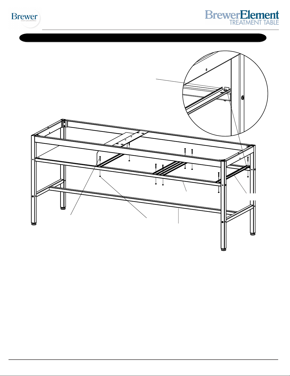
RH Side
MODELS 2230 and 2240 STEP 7
Detail of
Drawer Slide Bumpers
LH Side
Screw E
Drawer Support
Nut K
Drawer Slide
Shelf Support
STEP A: The Drawers can be installed so they open from the right hand side (RH Side) or the left hand side
(LH Side) of the table. The view above and the instructions below are for a right hand installation.
STEP B: Position the (4) Drawer Slides on top of the Drawer Support rails. The rubber bumpers should be
on the LH Side of the table, facing upward.
STEP C: Tighten Screws E (8-32 x 1 1/4”) into Nuts K (8-32) at 8 locations.
STEP D: Tighten all screws at this time.
-Legs to Frame (8 screws using Allen Wrench provided)
-Drawer Supports to Legs (4 screws)
-Shelf Support to Legs (4 screws)
Document 101294 RevA
10
Printed in USA © 2010
Page 11
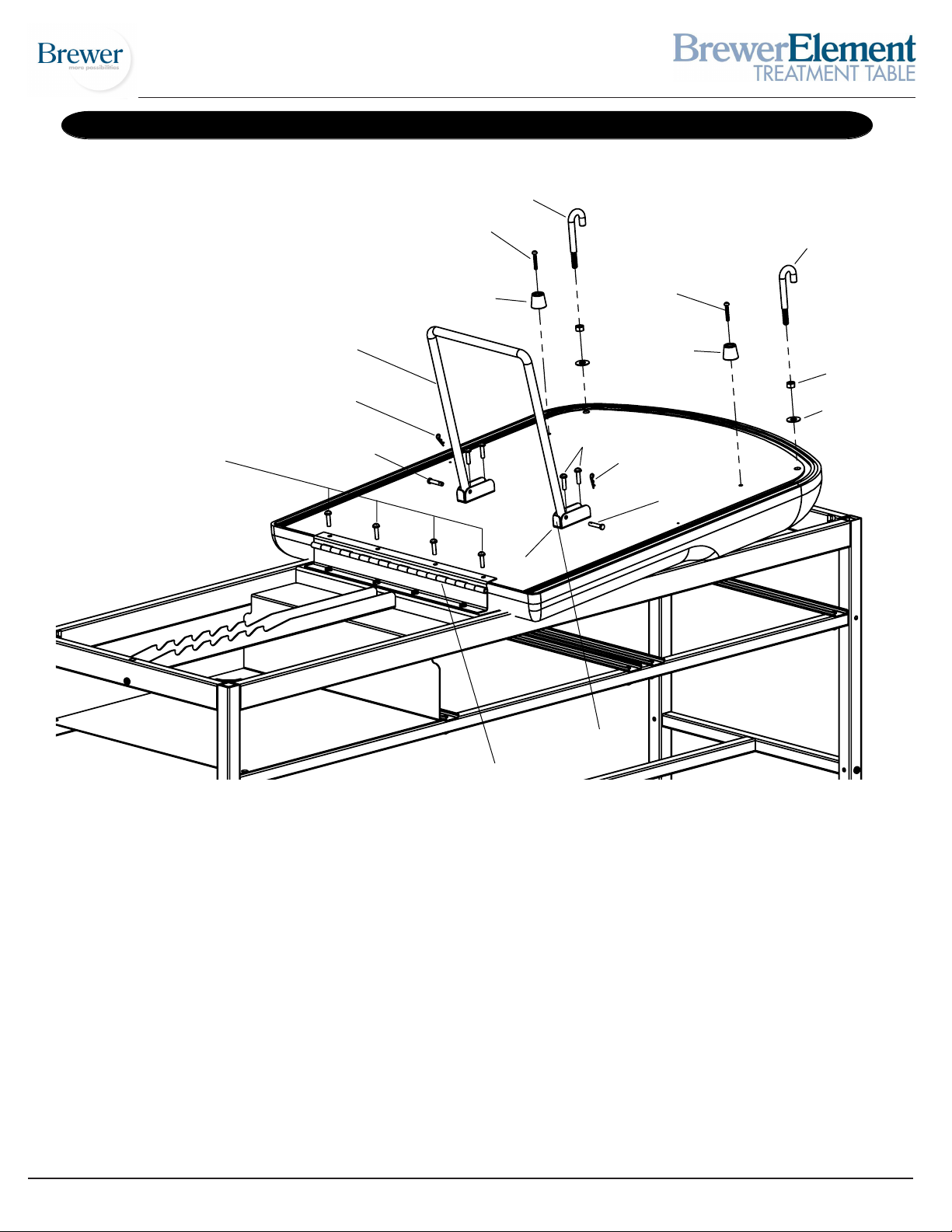
MODELS 2230 and 2240 STEP 8
J-Bolt R
Screw D
J-Bolt R
Screw F
Backrest Support
Cotter Pin
Clevis Pin
Bumper
Clevis
Screw F
Cotter Pin
Screw D
Bumper
Clevis Pin
Nut L
Washer M
Foot End
Clevis Tab
Hinge
STEP A: Lay upholstered backrest on Foot End of frame as shown.
STEP B: Slide backrest down until it bumps up against Hinge.
STEP C: Insert the four backrest-to-hinge Screws F (1/4”-20 x 1”) and tighten.
STEP D: Insert Screws F (1/4”-20 x 1”) through Clevises and tighten. Note Clevis Tab orientation.
STEP E: Install Backrest Support with Clevis Pins and Cotter Pins.
STEP F: Insert Screws D (10-24 x 1 1/4”) through Bumpers and tighten.
STEP G: Thread Nut L (3/8”) completely onto J-Bolt R. Place Washer M onto J-Bolt and thread into backrest
as shown. Position J-Bolt toward head end of table as shown and tighten nut against backrest.
Document 101294 RevA
11
Printed in USA © 2010
Page 12
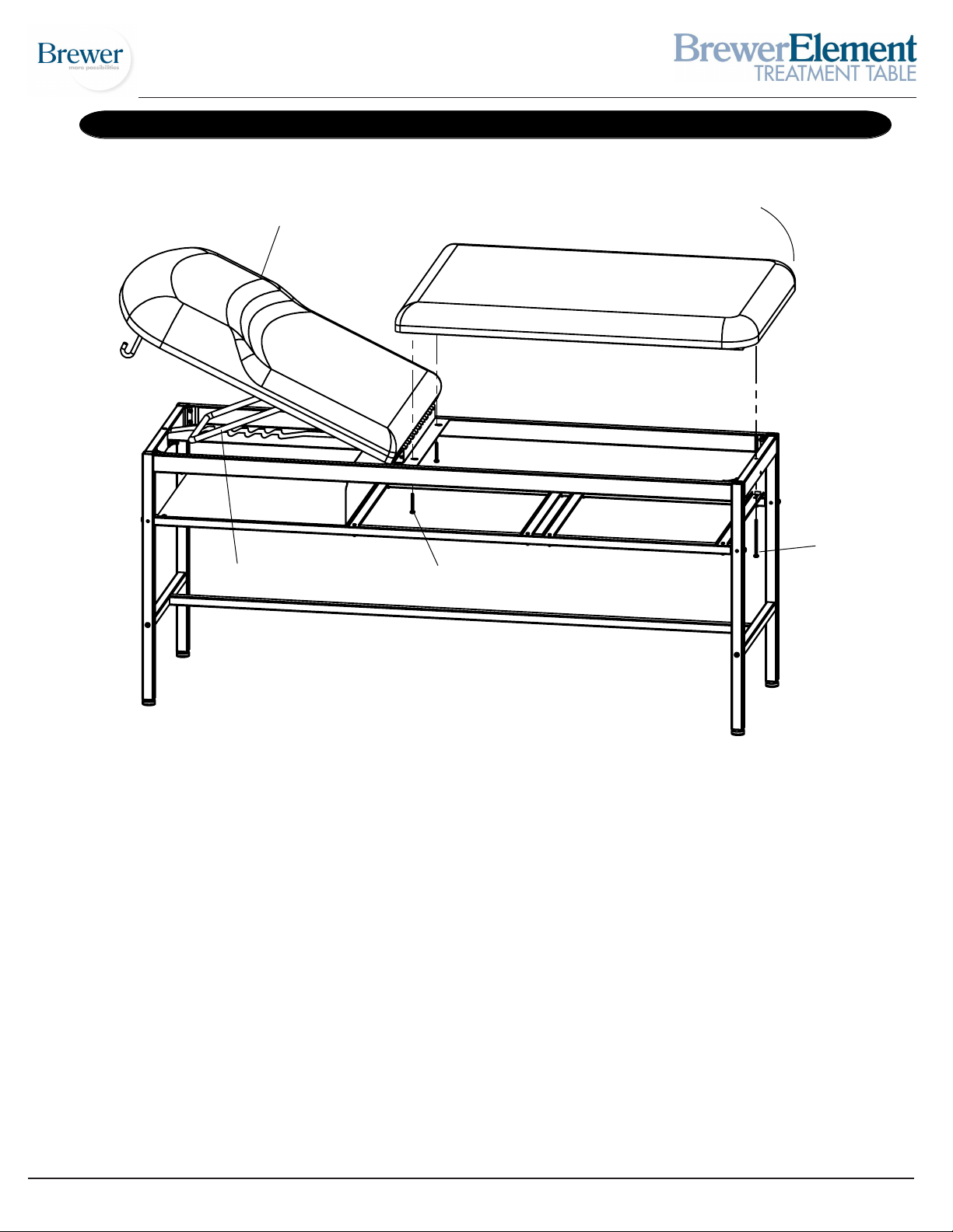
Back Section
MODELS 2230 and 2240 STEP 9
Rounded
Corner
Foot End
Screw A
Backrest Bracket
Screw B
STEP A: Rotate Back Section until Backrest Bracket is engaged or top is horizontal on frame.
STEP B: Set upholstery bottom on frame, with Rounded Corners placed at the Foot End of the table.
STEP C: Install Screw A (1/4”-20 x 4”) through frame and into upholstery.
STEP D: Install 2 Screws B (1/4”-20 x 2”) through frame and into upholstery.
STEP E: Tighten Screws.
Document 101294 RevA
12
Printed in USA © 2010
Page 13
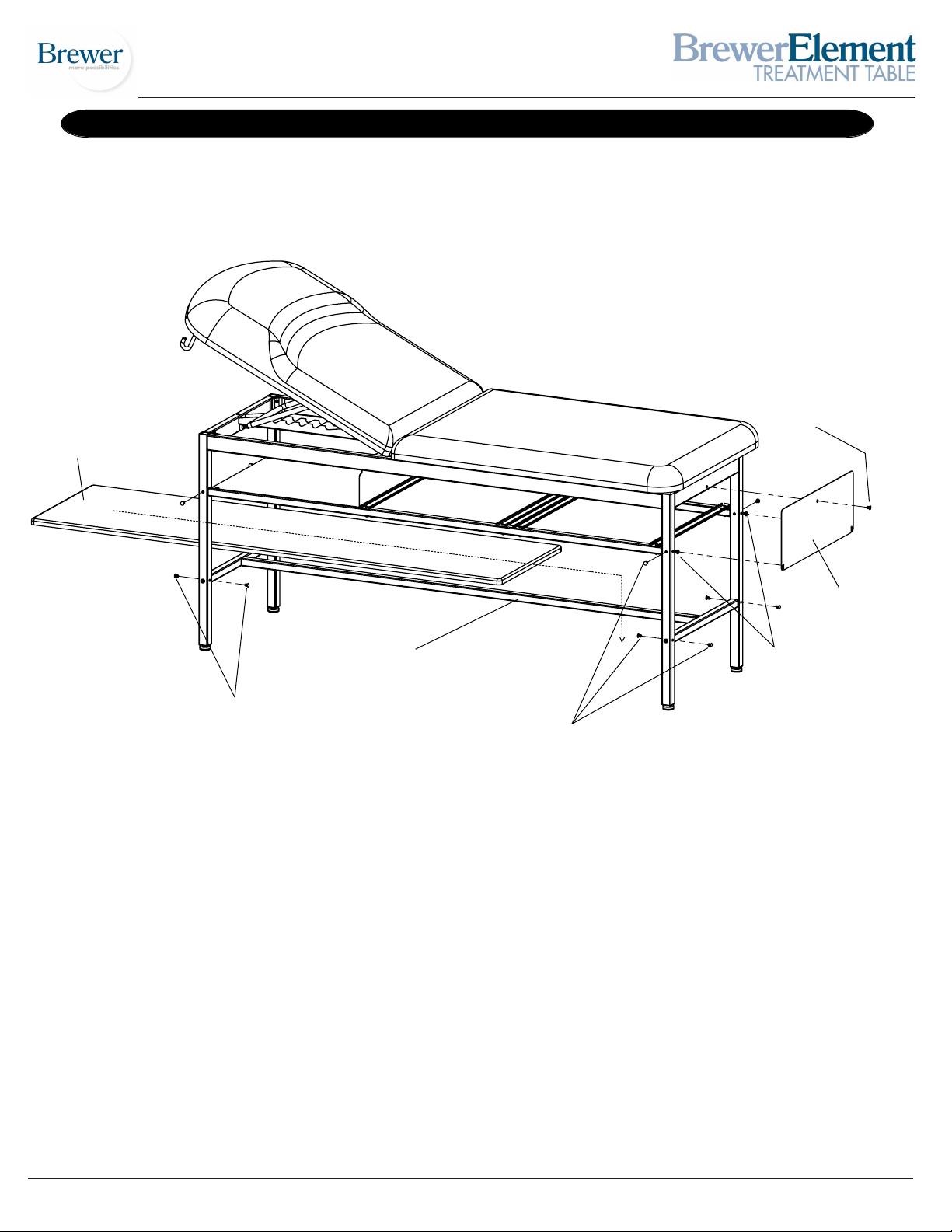
Shelf
MODELS 2230 and 2240 STEP 10
Snap Rivet
Side Plate
Lower Shelf Support
Screw B
Snap Rivet
Snap Rivet
STEP A: Loosen Screws B at the foot of the table where indicated just enough to allow installation of the
Side Plate.
STEP B: Mount Side Plate so that the slots of the plate straddle the Screws B that were just loosened.
STEP C: Press the top of the Side Plate up against the frame and align the top hole of the plate with the
hole in the frame. Insert Snap Rivet into the aligned holes.
STEP D: Retighten Screws B.
STEP E: Insert the Shelf through either end of the table. Positon the Shelf so that the locating blocks, on
the bottom of the Shelf, are straddling the Lower Shelf Support.
STEP F: Install Snap Rivets into unused holes in legs and frame.
Document 101294 RevA
13
Printed in USA © 2010
Page 14
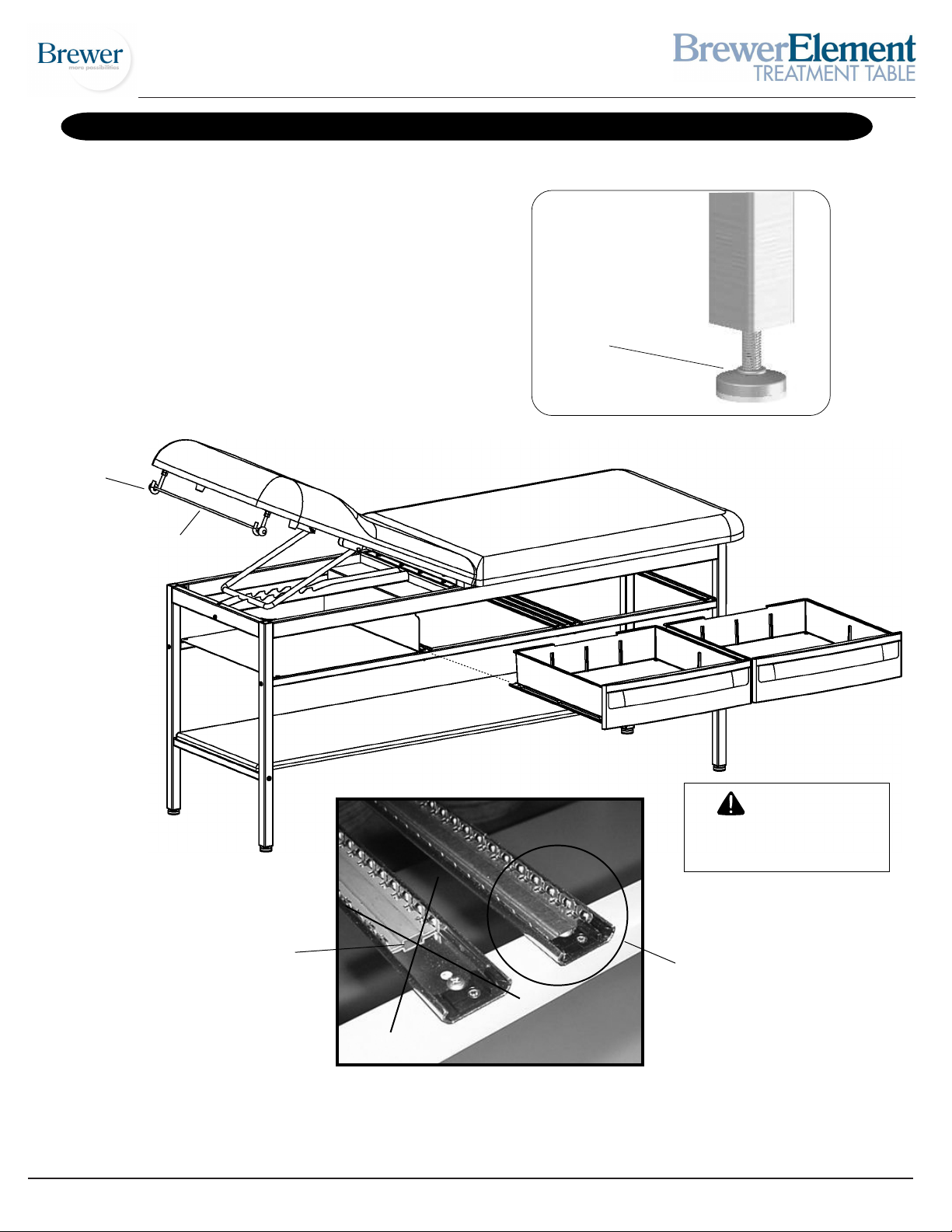
INSTALLATION
Leveling the Table (Figure A)
A Leveling Screw Pad is located at each corner under the
table’s base. Adjust the four Leveling Screw Pads, by turning
them up or down, to achieve a solid, level installation.
Installing the Paper Roll (Figure B)
Slide the Dowel Rod through the paper roll and hang
the Dowel Rod on the J-Bolts. Ensure a secure fit before
using the paper roll dispenser.
Leveling Screw Pad
Figure B
J-Bolt R
Dowel Rod
Figure A
Drawer Slide Positioning
CAUTION
MAXIMUM LOAD
15 LBS. PER DRAWER
Incorrect Positioning
Correct Positioning
To install drawers, pull drawer slides forward and align the slots of the drawer-mounted slides to their
mate on the frame. Push the drawers inward until they reach their fully-closed position.
Document 101294 RevA
14
Printed in USA © 2010
Page 15
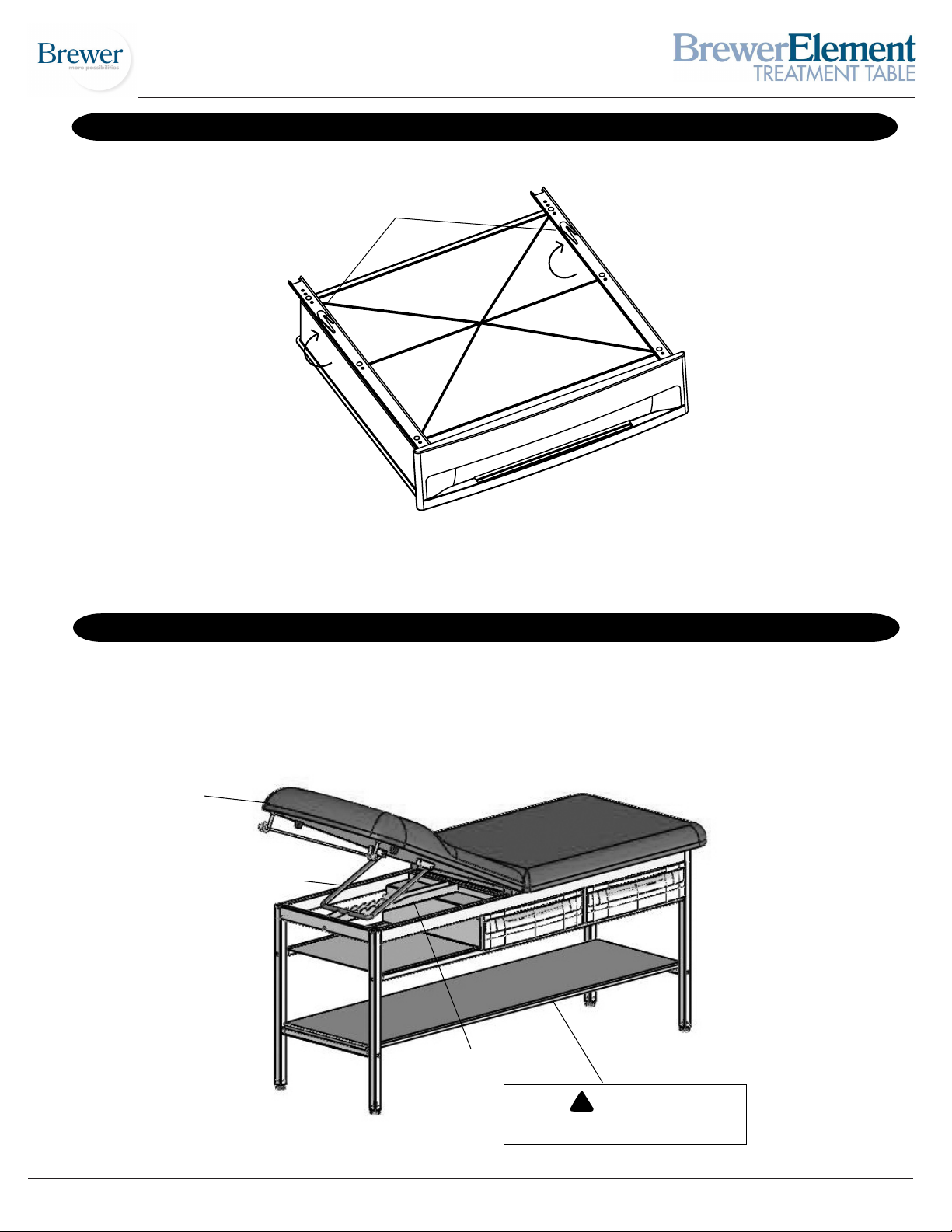
DRAWER REMOVAL
Retaining Clips
Drawer
(Bottom View)
To remove Drawer from bottom slide support: Fully extend the Drawer, locate the Retaining Clips and
push both clips in a clockwise direction as you pull the Drawer forward and out.
OPERATION
Back Section
To Raise Back Section: Lift Back Section of upholstery to desired inclination and secure Backrest Bracket into one
of the six Backrest Catch slots.
To Lower Back Section: Lift Back Section of upholstery and lift Backrest Bracket out of the Backrest Catch while
lowering the Back Section.
Back Section
Backrest Bracket
Backrest Catch
Document 101294 RevA
15
CAUTION
DO NOT USE SHELF AS A STEP!
Printed in USA © 2010
Page 16
MAINTENANCE
Preventative Maintenance
• Inspect the mechanical functions to ensure satisfactory operation.
• Check fasteners to make sure they are present and
secured tightly.
Cleaning
Upholstery
Regular care should be maintained by daily wiping with a
damp cloth or sponge and periodic cleaning with a mild
soap and water solution. Let air dry before placing anything on top of upholstery.
WARNING
The upholstery material that covers the top of the
table is resistant to most medicinal-type stains, but
may be damaged by solvents and dyes. Remove
any fluids which are spilled on the
immediately. All surfaces should be cleaned within
your facilities guidelines concerning antimicrobials
and bloodborne pathogens.
upholstery
Painted Metal Surfaces
Wipe all painted metal surfaces with a clean cloth at least
once a week.
Drawers
Wipe out drawers with a damp cloth or sponge on a regular
basis, along with periodic cleaning with a mild soap and water
solution. The drawers may be removed for cleaning. (See page
15.)
ACCESSORIES
Description Reorder No. Use/Restrictions
Replacement Upholstery
Special Upholstery 210115-SP Intended Use - Allows the purchase of
220115-SP specialty vinyls in different colors with the
Front Drawer Organizer 100407 Intended Use - Optional front drawer
dividers for separation and organization.
Paper Straps 10196 Intended Use - Secures paper in two
locations to table.
210115-XX Intended Use - Replacement top with
220115-XX
hardware for 2230 and 2240
Treatment Tables in 18 standard colors.
model 2230 and 2240 Treatment
Tables. (Additional charges may apply.)
LIMITED WARRANTY
The Brewer Company
GENERAL TERMS AND CONDITIONS
Warranty: The Brewer Company warrants its products to be free from defects in parts and workmanship under normal use
and service for a period of three (3) years from date of shipment. The Brewer Company warrants its power tables to be free from
defects in parts and workmanship under normal use and service for a period of three (3) years from date of shipment. The Brewer
Company warrants its exam tables to be free from defects in parts and workmanship under normal use and service for a period of
three (3) years from date of shipment. The Brewer Company warrants its lighting products to be free from defects in parts and
workmanship under normal use and service for a period of one (1) year from date of shipment. The Brewer Company will not be
responsible for any Product failure due to abuse, misuse, modification or improper use or for any use which exceeds the published
capacity of the Product. Products returned by prepaid freight for inspection and found defective will, at the option of The Brewer
Company, be repaired or replaced at no charge, but no claim for outside labor or other charges
returned without proper written authorization from The Brewer Company. Requests for authorization must be in writing and accompanied by the original purchase order, The Brewer Company invoice number and a copy of the invoice for the Product. THIS WARRANTY
IS EXCLUSIVE AND IN LIEU OF ALL OTHER WARRANTIES AND REMEDIES WHATSOEVER, INCLUDING BUT NOT LIMITED TO
IMPLIED WARRANTIES OF MERCHANTABILITY AND/OR FITNESS FOR A PARTICULAR PURPOSE. NO AGENT, EMPLOYEE, OR
REPRESENTATIVE OF THE BREWER COMPANY HAS ANY AUTHORITY TO MAKE ANY AFFIRMATION, REPRESENTATION, OR
WARRANTY NOT SET FORTH IN THESE TERMS AND CONDITIONS CONCERNING ANY PRODUCTS OF THE BREWER COMPANY. THE BREWER COMPANY SHALL HAVE NO LIABILITY WHATSOEVER FOR DAMAGES CAUSED BY TRANSPORTATION,
ACCIDENTS, FIRE, UNAUTHORIZED ALTERATION, OR NORMAL WEAR OR ABUSE, NOR SHALL THE BREWER COMPANY HAVE
ANY LIABILITY WHATSOEVER FOR
any such damages arising from (a) the design, manufacture, sale, delivery, installation, repair, operation or use of products of The
Brewer Company or any part thereof, (b) any actual or alleged failure or defect in products of The Brewer company or any part thereof,
or (c ) any actual or alleged breach or non-performance by The Brewer Company of this limited warranty.
Freight Claims: Upon receipt, merchandise should be carefully examined to ascertain that proper amount has been received in
good condition. Any claim for shortage or damage must be made with delivering carrier within five (5) days from receipt of goods.
We do not assume any responsibility for loss or damage in transit, and compensation for such loss must be obtained from the
carrier.
ANY INCIDENTAL OR CONSEQUENTIAL DAMAGES, including without limitation, lost profits or
will be allowed. Products must not be
Document 101294 RevA
16
Printed in USA © 2010
 Loading...