

Bretford UNI-3 User Manual
UNI3
ST AND-UP PRINTER ST AND
Assembly Instructions
P ARTS LIST
Qty Part# Description
2 010-1627 Machine Rests
4 010-1629 Extender Brackets
2 010-1894 Modesty Panels
3 010-1824 Shelves
1 014-0166 Wire Basket
1 022-1381 Right Pedestal Assembly
1 022-1382 Left Pedestal Assembly
TOOLS REQUIRED
Phillips Screwdriver
Adjustable Wrench
MODESTY
PANEL
HARDW ARE LIST
Ref Qty Part# Description
AA 4 015-0045 Floor Glides
BB 32 030-0325 1/4-20 x 1/2”Truss Screws
CC 12 030-0207 1/4-20 Flanged Hex Nuts
DD 4 030-0313-901 Machine Rest Cups
EE 4 030-0272 1/4-20 x 1/2” Carriage Bolts
FF 4 030-0274 Lock Washers
GG 4 030-0006 1/4-20 Wing Nuts
1 018-0034 13” Ground Wire
SHELF
SHELF
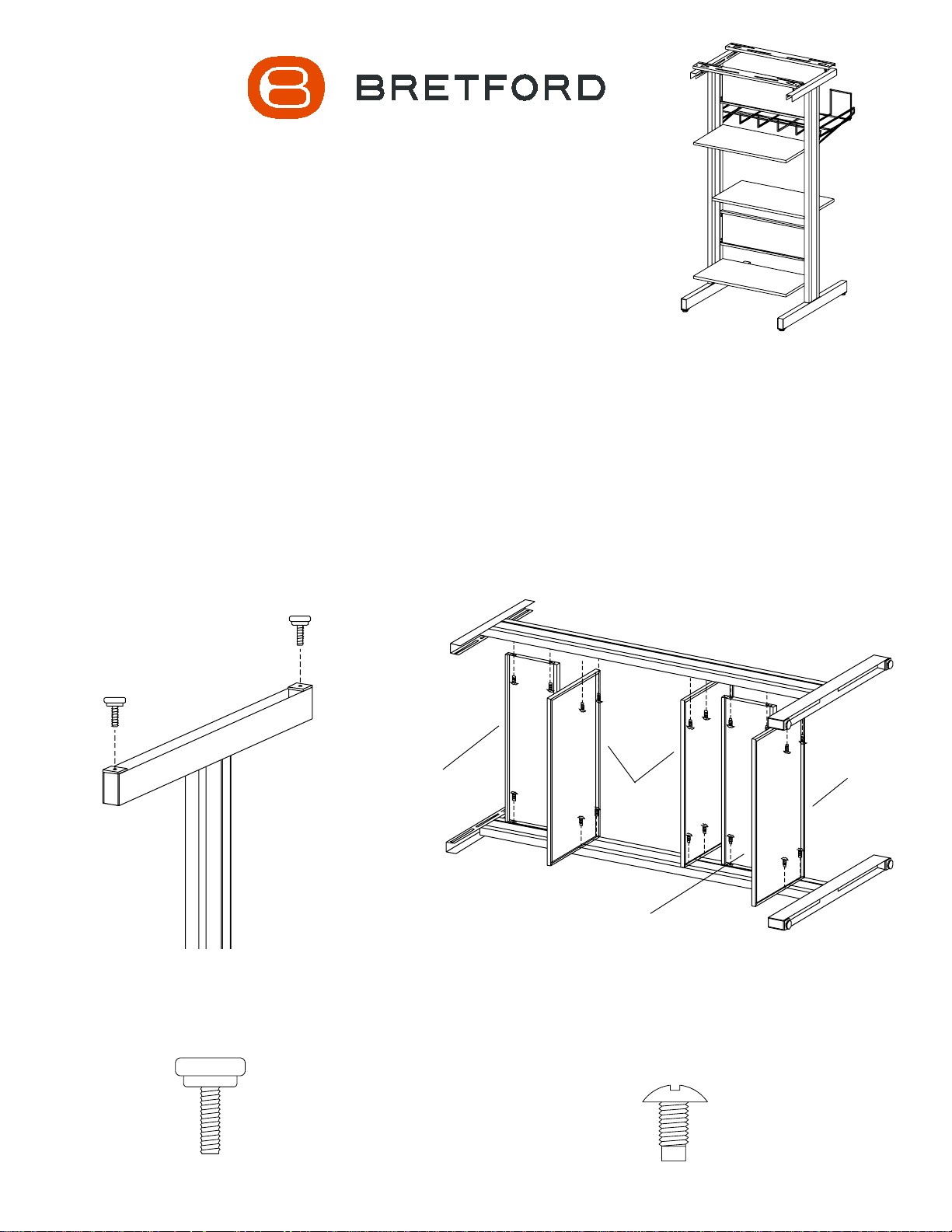
STEP 1
Twist on the floor glides (AA) onto the
bottom of both pedestals.
AA
MODESTY
P ANEL
STEP 2
Lay left pedestal on a flat surface with holes facing upward.
Attach modesty panels and shelves onto pedestal using
screws (BB) in order shown. Position other pedestal on
panels and attach with screws. Stand unit upright.
BB
STEP 3
Attach machine rests between pedestals
using screws (BB) and flange nuts (CC) as
shown. The spacing of the machine rests is
determined by your printer size.
CC
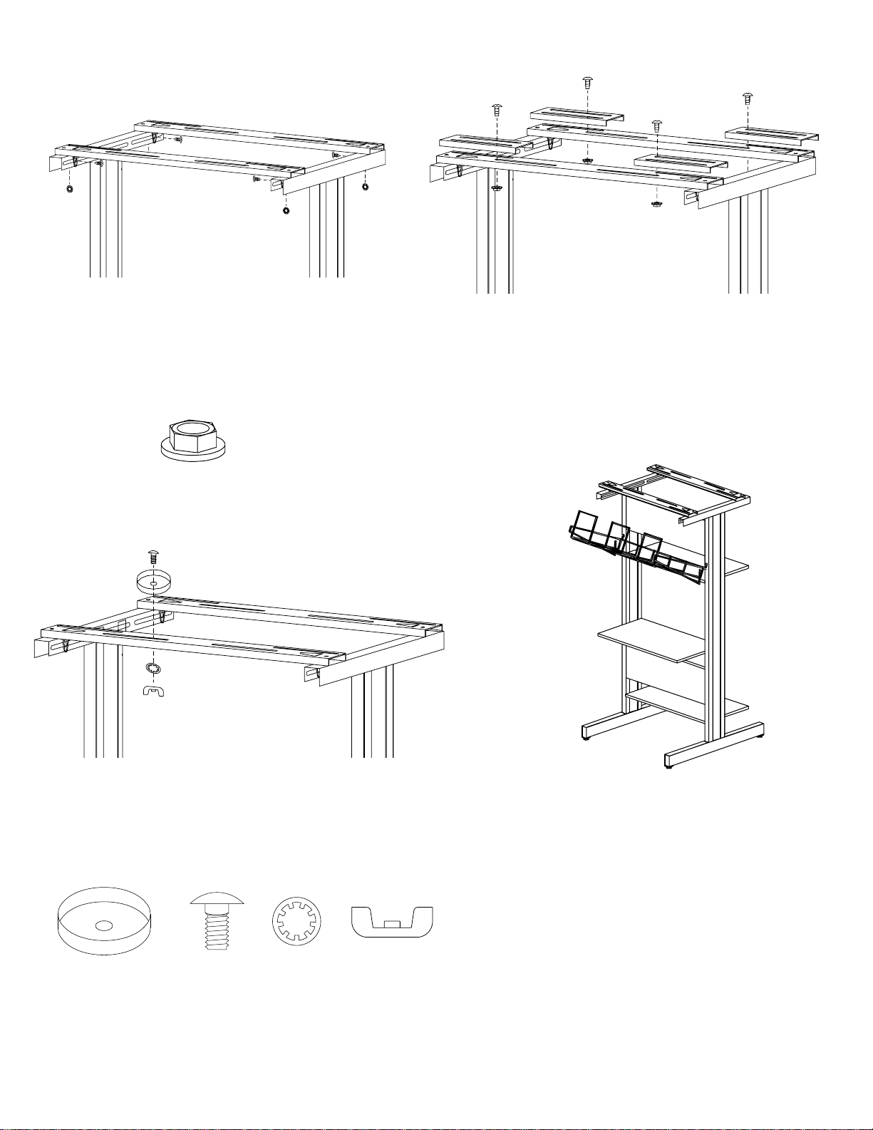
STEP 4
If printer is larger than printer stand, use the extender
brackets to give you additional length. Place extender
brackets on machine rests and fasten with screws (BB)
and flange nuts (CC) as shown. Slide extender brackets
out to desired.
STEP 5
Fasten machine rest cups (DD) onto machine rests OR
extender brackets (if used) using carriage bolts (EE),
washer (FF) and wing nut (GG) as shown. The location
of machine rest cups is determined by the printer size.
Once everything is attached, place your printer on stand.
GG
DD
EE
FF
Bretford Bretford Ltd.
11000 Seymour Avenue Technology House
Franklin Park, IL 60131 7 Lake End Court, Taplow
TEL: 847.678.2545 Bucks SL6 0JQ England
800.521.9614 TEL: 01628 603558
FAX: 847.678.0852 FAX: 01628 604923
800.343.1779
www.bretford.com
STEP 6
Hook wire basket into the slots on
the back of the unit.
NOTE: Included in your hardware
pack is ground wire. Consult your
printer manual for proper procedures.
Part# 031-1050
Rev. 09.24.97
 Loading...