

Bretford TC35FF, TC35 Assembly Instructions Manual
TC35 / TC35FF
HEIGHT ADJUSTABLE PRESENTATION
CART WITH AND WITHOUT POWER
PARTS LIST
Qty Part# Description
2 022-2479 Lower Left Front/Right Rear Legs
2 022-2480 Lower Right Front/Left Rear Legs
1 022-2474 Top Shelf
1 022-2688 Middle Shelf
1 010-4323 Bottom Shelf
2 010-4777 Side Panels
1 010-4778 Rear Panel
1 022-2689 Left Door
1 022-2690 Right Door
4 022-2836 Upper Leg Assemblies
2 010-4780 Keyboard Shelves
2 010-4779 Slide Brackets
2 030-1191 14” Full Extension Slides
2 015-0002 4” Casters w/o Lock
2 015-0003 4” Casters w/ Lock
1 CFPS UNIT Electrical Unit - TC35FF ONLY
HARDWARE LIST
Ref Qty Part# Description
AA 24 030-0300 5/8” Square Head Bolts
BB 24 030-0002 5/16”-18 Serrated Nuts
CC 2 030-0023 #6-32 x 3/8” Machine Screws
DD 2 030-0522 #6-32 Hex Nuts w/ External Teeth
EE 4 030-0383 #10 x 1/2” Truss Head Screws
FF 4 030-0325 1/4-20 x 1/2” Combo Screws
GG 16 030-1228 #8-32 x 1/4” Truss Screws
HH 8 030-1203 #8-32 Acorn Nuts
I I 4 030-0255 #10 x 5/8” Phillips Pan Hd Screws
JJ 10 02236 8-32 Hex Flange Nuts
KK 2 030-0302 8-32 x 3/8” Screws TC35FF ONLY
1 010-1188 Bottom Door Stop
2 012-0286 Plastic Handles
1 010-1106 Hex Wrench
TOOLS REQUIRED
Hex Wrench (Provided)
Phillips Screwdriver
Rubber Mallet (Optional)
FIGURE 2
FIGURE 1
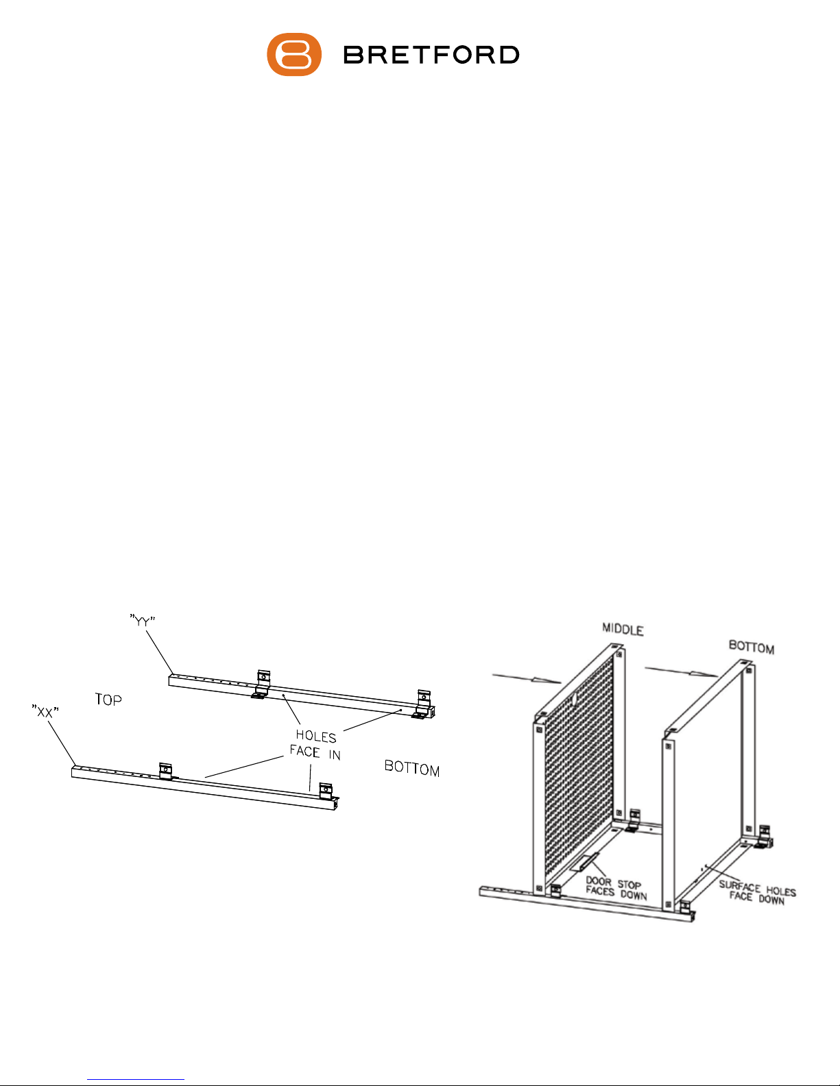
Position the lower front legs (stamped “XX” and “YY”) with the brackets facing
up and in as shown in FIGURE 1. Slide the bottom and middle shelves onto the
legs making sure the brackets are inside of the shelves as shown in FIGURE 2.
STEP 1
1
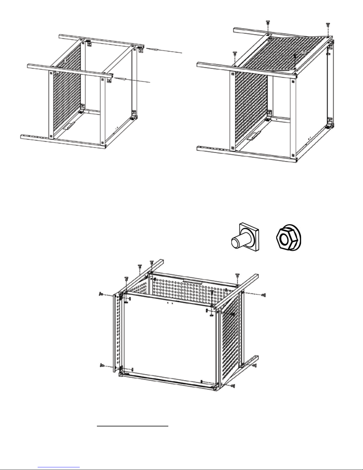
STEP 2
Slide the 2 remaining lower legs onto
the shelves as shown. Make sure the
brackets are inside the shelves.
STEP 3
Slide the rear panel between the middle and bottom
shelf so that the top ange is behind the leg brackets
and the bottom hooks onto the bottom shelf. Attach in
the 4 corners with bolts (AA) and nuts (BB) as shown.
AA
STEP 4
CAREFULLY turn the unit on its back. Attach each side panel in the same
manner as described in STEP 3 using bolts (AA) and nuts (BB) as shown.
BB
2
 Loading...