

Bretford TC15FF, TC15 Assembly Instructions Manual
TC15 / TC15FF
19” RACK PRESENTATION CART
WITH & WITHOUT POWER
Assembly Instructions
PARTS LIST
Qty Part# Description
2 022-2708 Leg Assembly Stamped with “X”
2 022-2709 Leg Assembly Stamped with “O”
1 022-2695 Top Shelf w/Grommet Hole
1 022-2699 Middle Shelf w/Grommet Hole
1 010-4791 Bottom Shelf
2 010-4785 Slide Bracket
2 030-1191 Slide
2 010-4780 Keyboard Shelf
1 010-4788 Front Panel
1 010-4789 Rear Panel
2 022-2697 Left Door Assembly
2 022-2698 Right Door Assembly
1pr. 030-1206 Rack Rail
4 010-4799 Rail Bracket
2 010-4867 Utility Shelf
2 015-0002 4” Caster w/o Brake
2 015-0003 4” Caster w/ Brake
1 UCSE10 Electrical Unit - TC15FF ONLY
HARDWARE LIST
Ref Qty Part# Description
AA 24 030-0300-10T 5/8” Square Head Bolts
BB 24 030-0002 5/16-18 Hex Serrated Nuts
CC 36 030-0325 1/4-20 x 1/2” Combo Screws
DD 16 030-0240 1/4” External Lockwashers
EE 16 030-1228 8-32 x 1/4” Combo Truss Hd Screws
FF 8 030-1203 #8-32 Acorn Nuts
GG 10 02236 8-32 Hex Flange Nuts
HH 4 030-0023 #6-32 x 3/8” Rnd Hd Machine Screws
I I 4 030-0522 6-32 Locknuts
JJ 8 030-0256 1/4-20 Flange Nuts
KK 2 030-0302 #8-32 x 3/8” Screws - TC15FF ONLY
MM 8 030-0402 #10-32 x 5/8” Combo Screws
NN 8 030-0383 #10 x 1/2” “AB” Truss Hd Screws
1 010-1106 Hex Wrench
2 010-1188 Door Stop Brackets
4 012-0286 Plastic Door Handles
TOOLS REQUIRED
Hex Wrench (Provided)
Phillips Screwdriver
Rubber Mallet
1
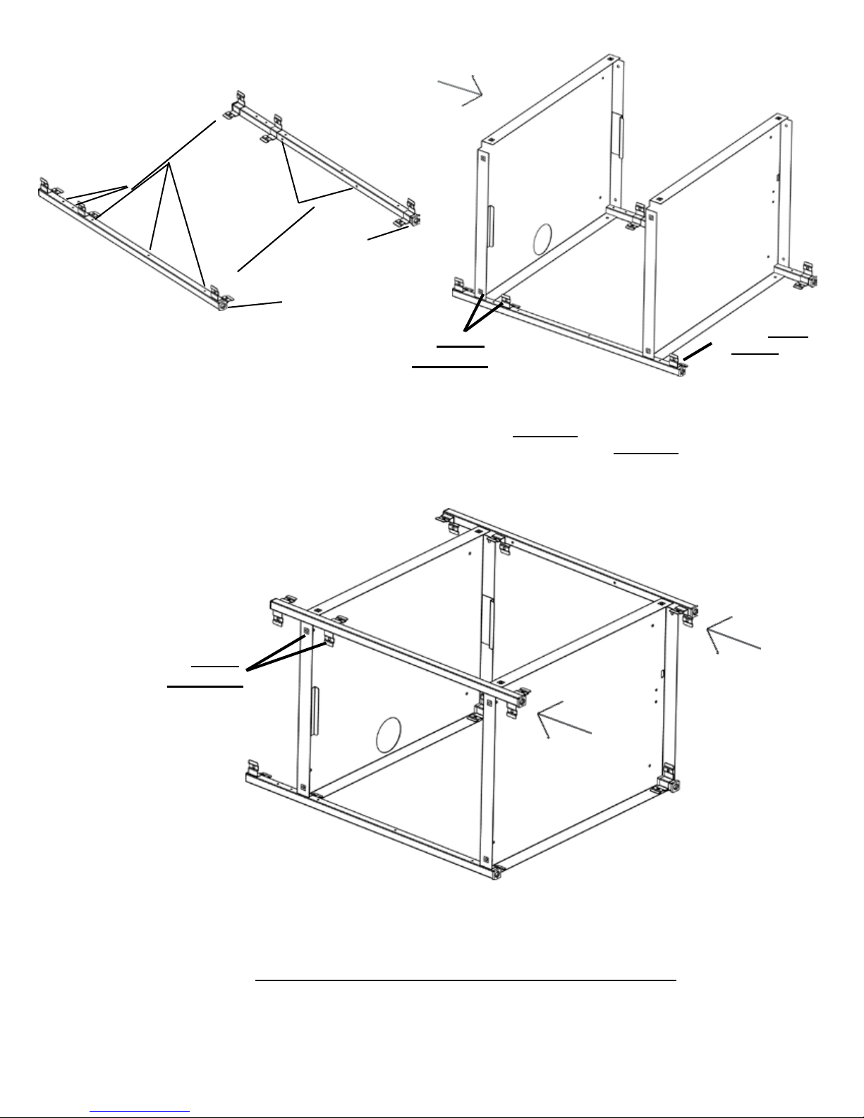
FIGURE 1
FIGURE 2
These 5 holes
MUST FACE UP
These 2 holes
MUST FACE IN
LEG BOTTOMS
Holes MUST
ALIGNED
be
STEP 1
Lay the rear legs on a carpeted surface exactly as shown in FIGURE 1. Slide bottom and
middle onto the legs so that the brackets are inside the shelves as shown in FIGURE 2.
Holes MUST
be ALIGNED
Bracket MUST
t INSIDE
shelf
Slide the front legs onto the shelves so that the brackets are inside the shelves as
shown. NOTE: Make sure all bracket holes are aligned with the shelf holes.
STEP 2
2

FULLY
TIGHTEN
THESE
ON BOTH
SIDES
ONLY INSTALL IN
THESE LOCATIONS
BOTH SIDES
STEP 3
HAND TIGHTEN shelves and legs with bolts (AA) and nuts (BB).
ONLY install side hardware and middle shelf hardware as indicated.
FULLY TIGHTEN MIDDLE SHELF HARDWARE.
AA
BB
Insert each caster into the bottom of each leg. If caster does not insert easily,
use a rubber mallet to tap caster in place. Once caster are SECURELY in
place, stand unit upright.
STEP 4
3
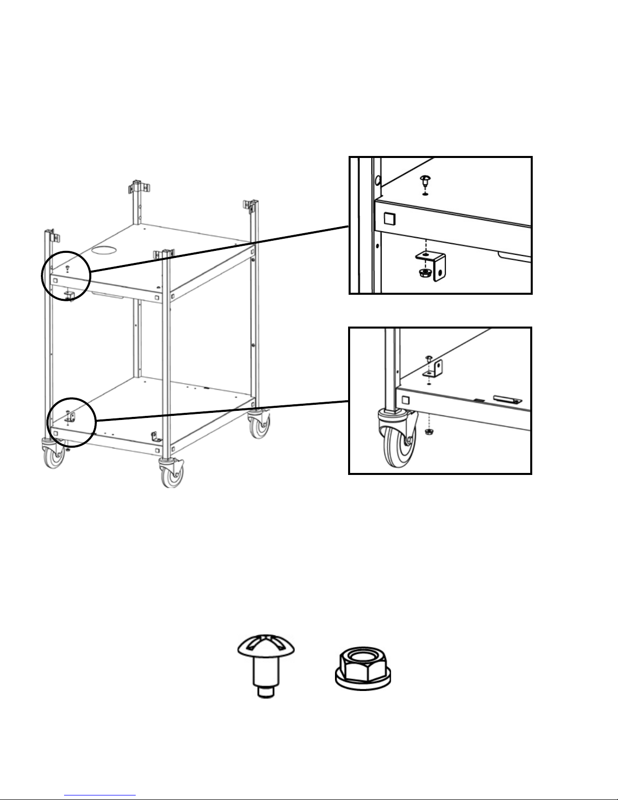
MIDDLE SHELF ATTACHMENT
BOTTOM SHELF ATTACHMENT
STEP 5
Attach L-brackets to one side of the cart. These should be mounted on
the side that you wish the utility shelves to be installed on. Attach each
bracket (2 per shelf) with screws (CC) and nuts (JJ) as shown.
CC
JJ
4
 Loading...