

Bretford TC12FF, TC12 Assembly Instruction Manual
TC12 / TC12FF
PRESENTATION CART WITH
AND WITHOUT POWER
PARTS LIST
Qty Part# Description
1 022-2695 Top Shelf w/ grommet hole
2 010-4780 Keyboard Shelves
1 010-3953 Bottom Shelf
2 010-4785 Slide Brackets
1 022-2692 Right Front Leg
1 022-2691 Left Front Leg
1 022-2694 Right Rear Leg
1 022-2693 Left Rear Leg
1 022-2309 Wire Tray
2 015-0002 4” Casters w/o Lock
2 015-0003 4” Casters w/ Lock
2 030-1191 14” Full Extension Slides
1 CFPS UNIT Electrical Unit - TC12FF ONLY
Rear Legs - Stamped LR & RR
HARDWARE LIST
Ref Qty Part# Description
AA 16 030-0300-10T 5/8” Square Head Bolts
BB 16 030-0002 5/16-18 Hex Serrated Nuts
CC 12 030-0325 1/4-20 x 1/2” Combo Screws
DD 16 030-1228 8-32 x 1/4” Combo Truss Hd Screws
EE 8 030-1203 #8-32 Acorn Nuts
GG 2 030-0302 #8-32 x 3/8” Screws - TC12FF ONLY
HH 10 02236 8-32 Hex Flange Nuts
I I 20 030-0240 1/4” External Lockwashers
1 010-1106 Hex Wrench
TOOLS REQUIRED
Hex Wrench (Provided)
Phillips Screwdriver
Rubber Mallet
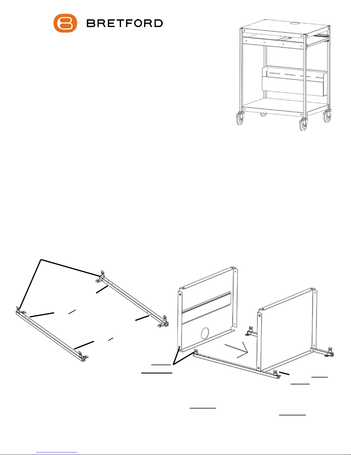
FIGURE 2
UP as shown
These holes should
face
IN as shown
These holes should
face
FIGURE 1
Lay the rear legs on a carpeted surface exactly as shown in FIGURE 1. (They are stamped “LR” & “RR”) Slide
bottom shelf and top shelf onto the legs so that the brackets are inside the shelves as shown in FIGURE 2.
Holes MUST
be ALIGNED
Bracket MUST t
INSIDE shelf
STEP 1
1
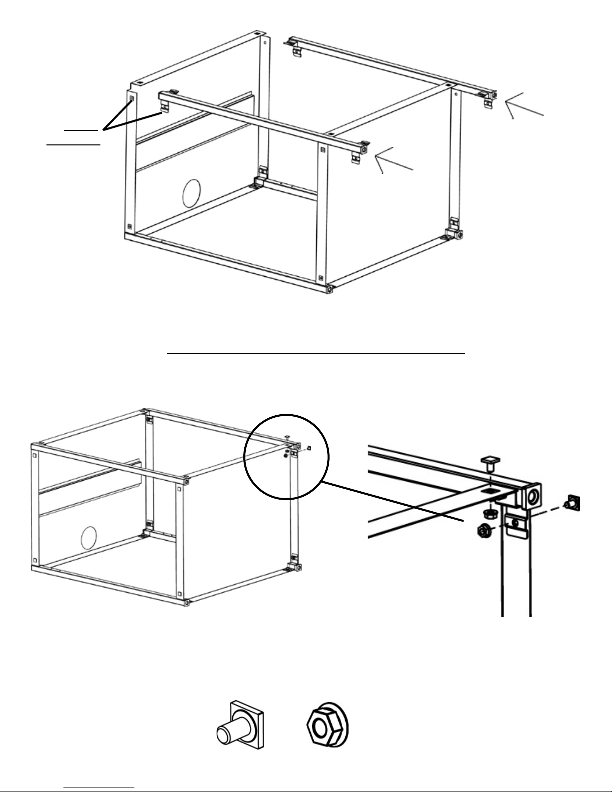
Holes MUST
ALIGNED
be
STEP 2
Slide the front legs onto the shelves so that the brackets are inside the shelves as
shown. NOTE: Make sure all bracket holes are aligned with the shelf holes.
Secure shelves and legs together with bolts (AA) and
nuts (BB) in each corner as shown.
AA
STEP 3
BB
2
 Loading...