

Bretford M-SUB Assembly Instructions Manual
SUBST A TION AND CHANNEL
LIQUID™ WORKSP ACE
Assembly Instructions
MODEL:
M-SUB
TOOLS REQUIRED
1/2” WRENCH
PHILIPS SCREWDRIVER
3/8” WRENCH
ELECTRIC HAND DRILL
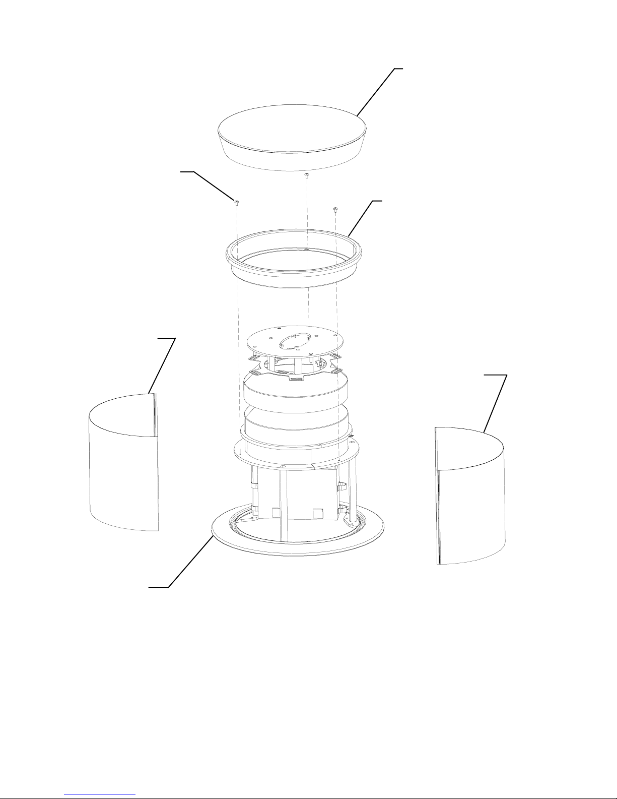
Substation
TracPlate
Screw
Substation Skin
Substation T op Cover
Substation Track
Plate
Substation Skin
Fig. 1
Substation Skirt
STEP 1
Remove Substation T op Cover by pulling it up. Disassemble Substation T rack
Plate and Substation Skins by removing three Substation Track Plate screws (Fig.
1). Save hardware for reassembly.
Note:
Power connection using power infeed should be performed by
qualified electrician.
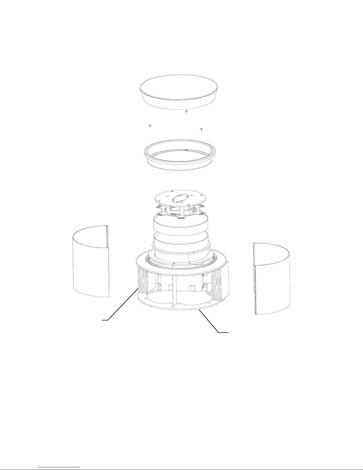
Wooden Block
Lift Substation Skirt up and hold it in place with two wooden blocks 7” long (Fig. 2).
Mark bolt hole pattern (3 holes) on the floor using hole locations in mounting plate
as template. Move Substation aside.
Fig. 2
STEP 2
Mounting plate
 Loading...