

Bretford MSB-C144 Assembly Instructions Manual
POWER POLE SUBSTATION
LIQUID™ WORKSP ACE
Assembly Instructions
MODEL:
MSB-C144
SAFETY W ARNING
Note: TWO PERSON
ASSEMBLY REQUIRED
CAUTION:
T urn off all power prior to connecting or disconnecting
the liquid electrical components.
P ARTS LIST
Qty Part No. Description
1 039-0200 RACEWA Y POWER POLE-144”
1 039-0005 SUBST ATION T OP COVER
1 039-0308 PLUG-OPEN 3/4” OV AL CONDUIT
1 010-3945 COVER PLA TE-POWER POLE
HARDWARE LIST
Qty Part No. Description
1 044-1713 HARDWARE P ACK
(4 EA. 1/4-20 x 3/4” HEX HD.SCW.)
TOOLS REQUIRED
KEY HOLE SAW
3/8” SOCKET WRENCH
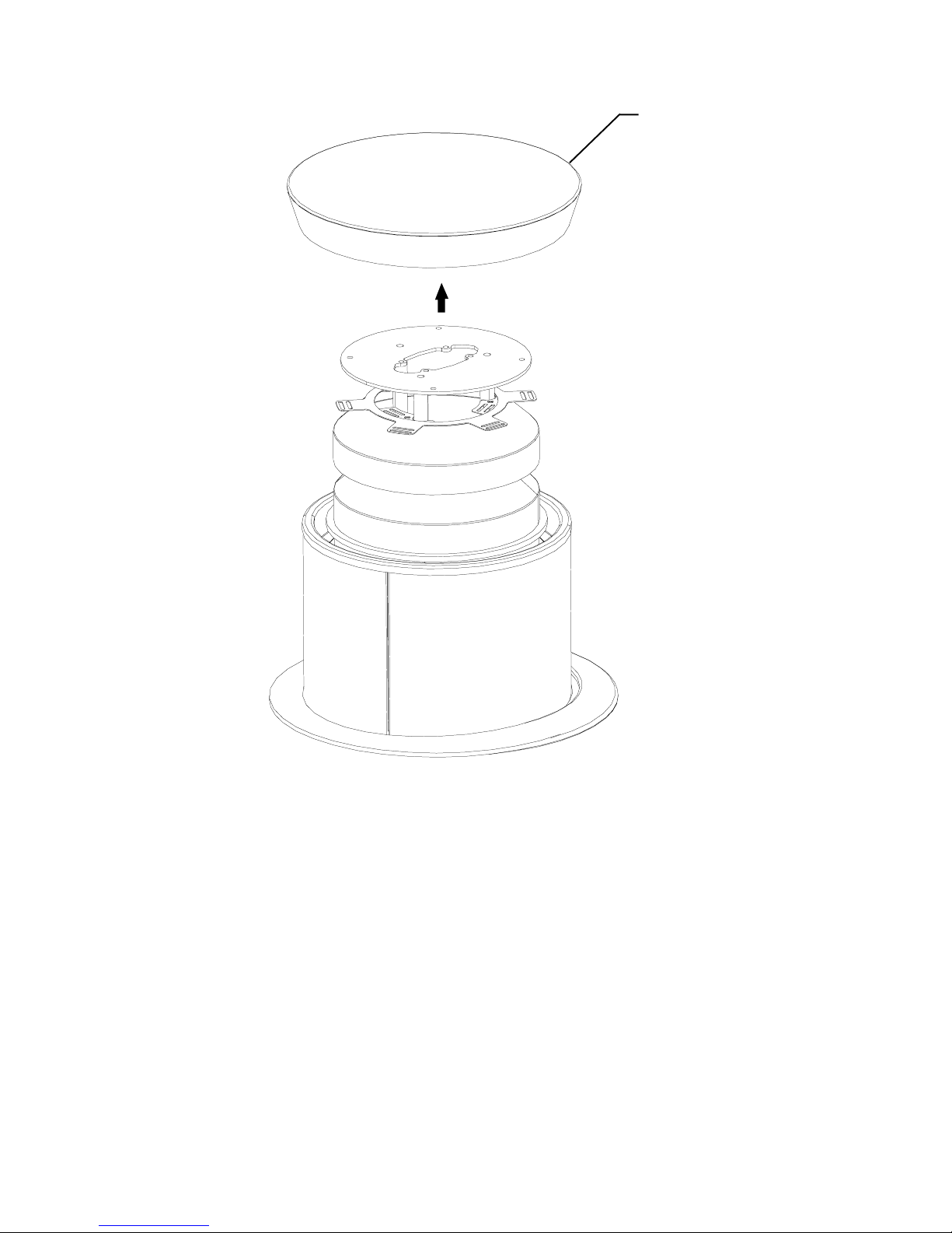
T op Cover
Note:
Substation must be anchored to floor when used for power
infeed. See Substation instruction sheets for anchoring
instructions.
Remove T op Cover . Discard existing Top Cover . Use the new
T op Cover with an oval cutout in the center .
Fig. 1
STEP 1
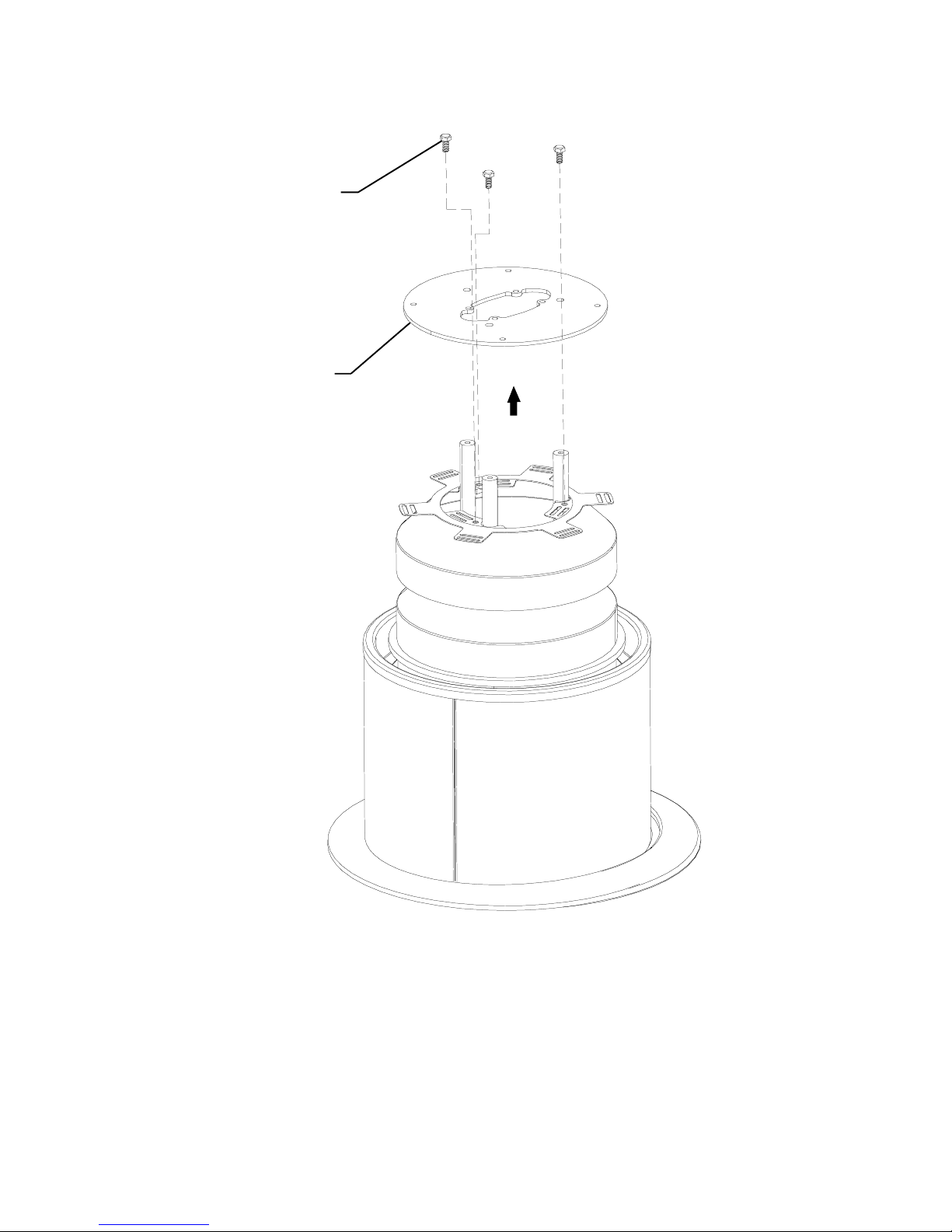
Cover Pin Plate
Hex Bolt
Cover Pin
Plate
Disassemble Cover Pin Plate by unfastening the Cover Pin Plate Hex Bolts. Save
hardware for reassembling.
Fig. 2
STEP 2
 Loading...