


POWER AND
DATA BLOCK
LIQUID™ WORKSP ACE
Assembly Instructions
MODELS:
MPD-15
MPD-26
MPD-33
MPD-44
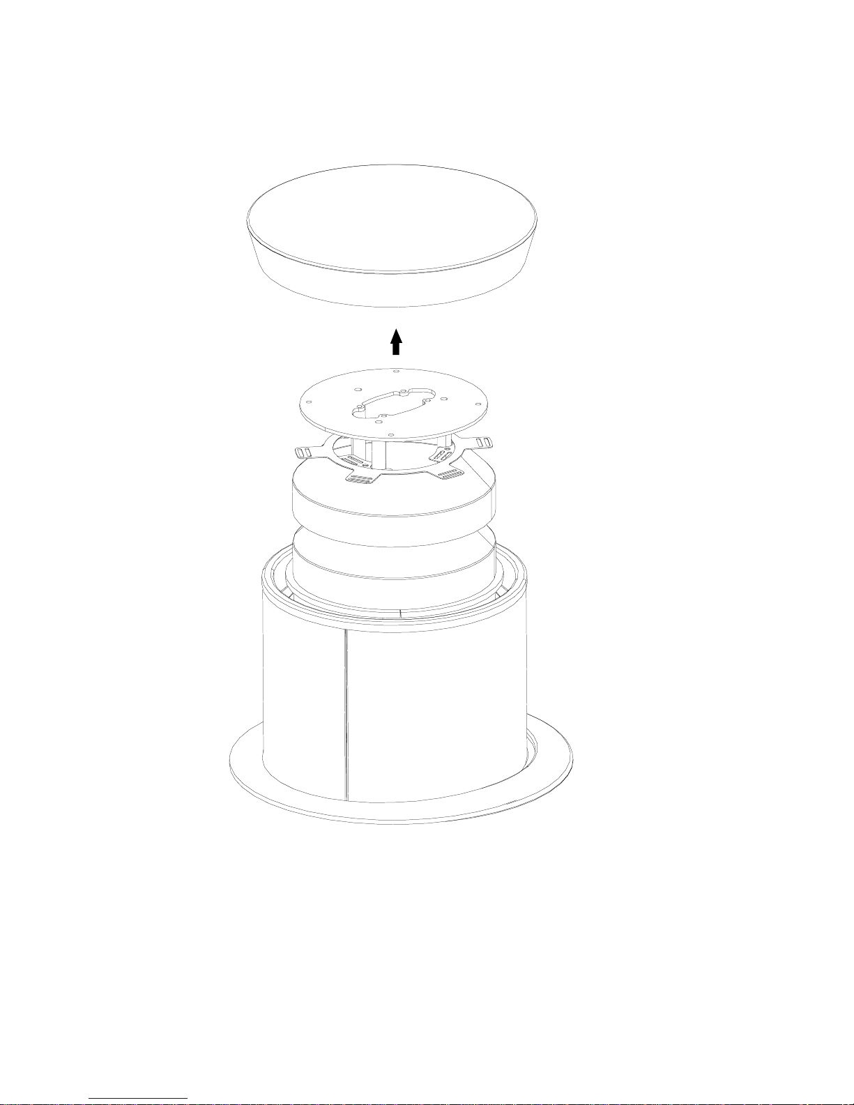
Remove Substation T op Cover by pulling it up.
Fig. 1
STEP 1

Cover Pin Plate Bolt
Cover Pin
Plate
Substation
Spider
Disassemble Cover Pin Plate and Substation Spider by unfastening the Cover Pin Plate
Hex Head Bolts. Save hardware for reassembling.
Fig. 2
STEP 2

Metal Visual Blocker
Screw
Metal Visual
Blocker
Disassemble Metal Visual Blocker by unfastening the three Metal Visual
Blocker Round Head Screws. Save hardware for reassembling.
Fig. 3
STEP 3

Power
Ring
Hex Bolt
Jumper
Power/Data
Block
Curved Cam
(must turn 1/4” rotation
to fit in)
Fig. 4
Substation Skin
Open Position
Slide one half of lower compartment closure inside other half to access Junction Box.
Thread the Jumper end through the Substation and plug into Junction Box (Fig. 4).
Place the Power/Data Block into power ring of Substation by aligning Curved Cam
and Pins with groove in Power Ring. Curve Cam must be positioned so when tightening Hex Bolt, Curved Cam rotates toward center of Substation.
Junction
Box
STEP 4
Fig. 4 shown with parts
removed for clarity

Locking Bolt
STEP 5
Lock the Power/Data Block in desired position by
turning the Locking Bolt Clock-wise. Reassemble
Visual Blocker , Substation Spider and Cover Pin
Plate (Fig. 5). Refer to steps 2 & 3.
Fig. 5
T op Cover
Stud
Cover Pin
Plate
Fig. 7
Fig. 6
Replace T op Cover , while aligning the studs in the T op Cover with Cover Pin
Plate holes (Fig. 6 & 7).
Bretford Bretford Ltd.
11000 Seymour Avenue Technology House
Franklin Park, IL 60131 7 Lake End Court, Taplow
TEL: 847.678.2545 Bucks SL6 0JQ England
800.521.9614 TEL: 01628 603558
FAX: 847.678.0852 FAX: 01628 604923
800.343.1779
www.bretford.com
STEP 6
Part #031-6469
Rev. 07.02.03 IM
 Loading...