

Bretford MCH-P120C, MCH-P48C, MCH-P144C, MCH-P72C, MCH-P96C Assembly Instructions Manual
Chicago Power Channel
Assembly Instructions
MODELS:
MCH-P48C
MCH-P72C
MCH-P96C
MCH-P120C
MCH-P144C
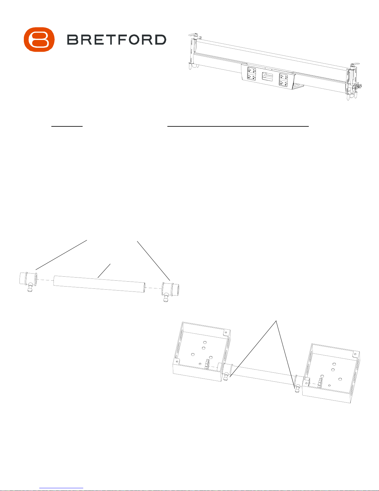
1/2 EMT SCREW
CONNECTORS
6 5/8 CONDUIT
FIGURE 1
CUSTOMER PURCHASED HARDWARE LIST
(QUANTITIES TO BE DETERMINE BY INSTALLER)
4 x 4 x 1 9/16 Deep Electrical Boxes
Conduit Approximately 6 5/8 Long
1/2 EMT Screw Connectors
Combination Coupling EMT to Flex Size 1/2 to 1/2
Conduit Approximately 19 3/4 Long
1/2 Flex Tubing
4 x 9/16 Deep Decorator Plates
Decorator Duplex Receptacles
Conduit Hangers
MAKE SURE CONNECTOR SCREWS
FACE THE FLOOR WHEN UNIT IS
ATTACHED TO CHANNEL
Attach a 1/2 EMT Screw Connector to each end of the conduit as shown
in FIGURE 1. Slide the conduit-connector assembly onto the electrical
boxes as shown in FIGURE 2. DO NOT FULLY TIGHTEN AT THIS
TIME.
NOTE: Remove belly pan by grasping one side and applying pressure outward and downward.
FIGURE 2
STEP 1
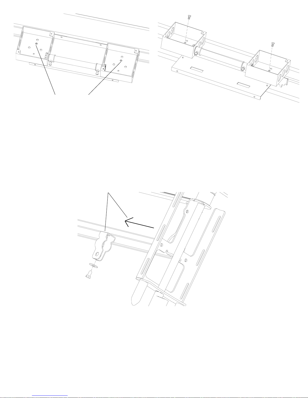
FIGURE 3
ATTACHMENT
HOLES
STEP 2
Position the box assembly to the channel using screws provided. Once assembly
is attached to channel, tighten conduit. NOTE: The attachment holes are marked
in FIGURE 3. DO NOT USE THE SMALL THREADED GROUND HOLE FOR
ATTACHMENT.
NOTE: The number of box assemblies will vary depending on the length of your channel.
PLACE HANGER 6
FROM END OF
CHANNEL
Attach 1/2 conduit hanger to channel approximately 6 from the end. Using
supplied screws and washers HAND TIGHTEN hanger to channel as shown.
NOTE: TO AVOID STRIPPING SCREW, DO NOT USE POWER TOOLS.
STEP 3
 Loading...