

Chicago Power Channel
Assembly Instructions
MODELS:
MCH-P48C
MCH-P72C
MCH-P96C
MCH-P120C
MCH-P144C
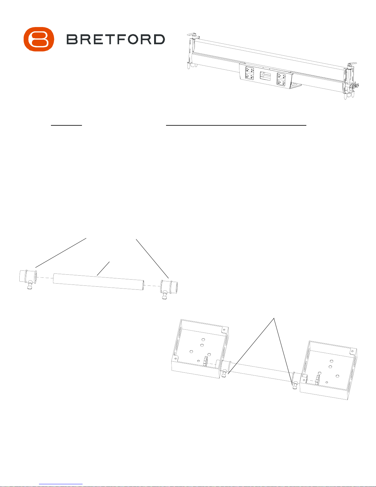
1/2 EMT SCREW
CONNECTORS
6 5/8 CONDUIT
FIGURE 1
CUSTOMER PURCHASED HARDWARE LIST
(QUANTITIES TO BE DETERMINE BY INSTALLER)
4 x 4 x 1 9/16 Deep Electrical Boxes
Conduit Approximately 6 5/8 Long
1/2 EMT Screw Connectors
Combination Coupling EMT to Flex Size 1/2 to 1/2
Conduit Approximately 19 3/4 Long
1/2 Flex Tubing
4 x 9/16 Deep Decorator Plates
Decorator Duplex Receptacles
Conduit Hangers
MAKE SURE CONNECTOR SCREWS
FACE THE FLOOR WHEN UNIT IS
ATTACHED TO CHANNEL
Attach a 1/2 EMT Screw Connector to each end of the conduit as shown
in FIGURE 1. Slide the conduit-connector assembly onto the electrical
boxes as shown in FIGURE 2. DO NOT FULLY TIGHTEN AT THIS
TIME.
NOTE: Remove belly pan by grasping one side and applying pressure outward and downward.
FIGURE 2
STEP 1
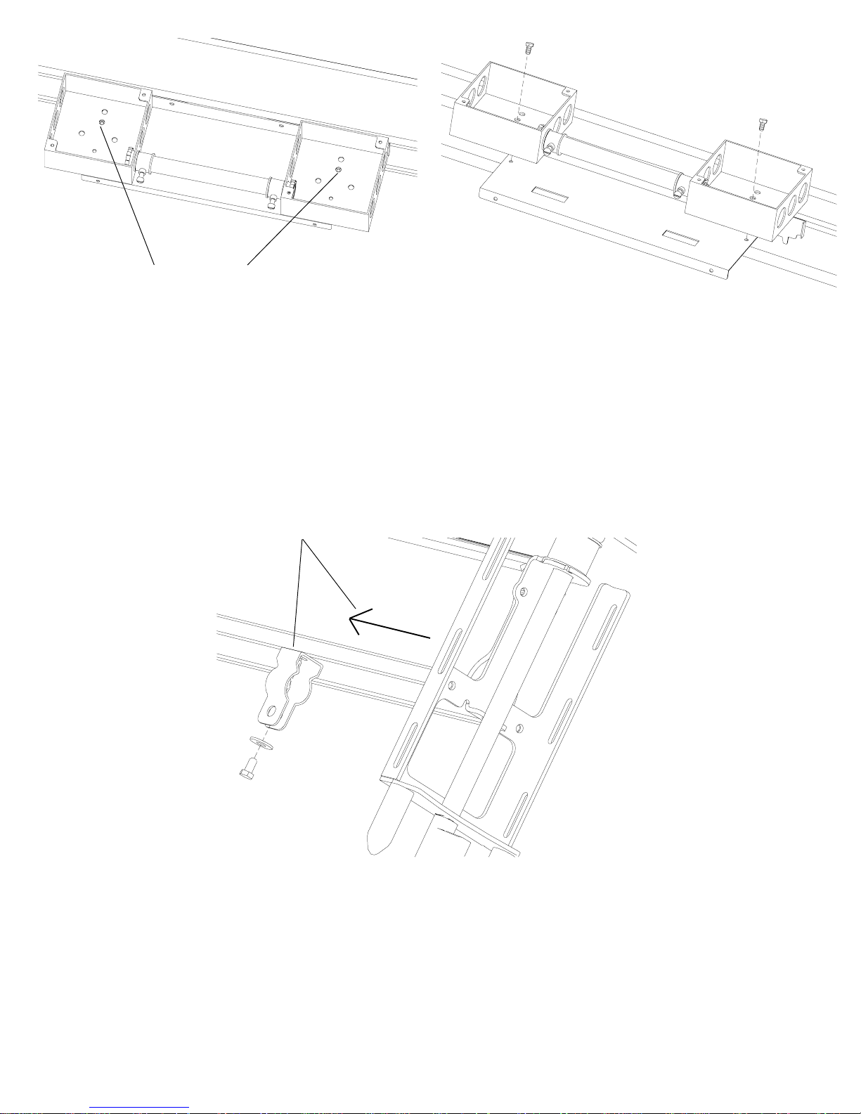
FIGURE 3
ATTACHMENT
HOLES
STEP 2
Position the box assembly to the channel using screws provided. Once assembly
is attached to channel, tighten conduit. NOTE: The attachment holes are marked
in FIGURE 3. DO NOT USE THE SMALL THREADED GROUND HOLE FOR
ATTACHMENT.
NOTE: The number of box assemblies will vary depending on the length of your channel.
PLACE HANGER 6
FROM END OF
CHANNEL
Attach 1/2 conduit hanger to channel approximately 6 from the end. Using
supplied screws and washers HAND TIGHTEN hanger to channel as shown.
NOTE: TO AVOID STRIPPING SCREW, DO NOT USE POWER TOOLS.
STEP 3

STEP 4
Loosely attach a connector to the electrical box as shown.
TIGHTEN ONCE
CONDUIT IS IN PLACE
Slide a 19 3/4 (approximately) piece of conduit through hanger and connector.
Tighten hanger and connector. Then wire as needed and install duplexes.
WARNING: Wiring must be done by a licensed electrician.
WARNING: Limited to a maximum of (3) 20 amp circuits per side.
SECURE IN PLACE WITH
HARDWARE SUPPLIED
WITH THE HANGER
STEP 5

Flex Tubing
STEP 6
Install a combination coupling to the end of the
conduit as shown to accept the flex tubing.
Conduit
Floor
Monument
For your first channel, attach the correct amount of flex tubing
between channel and floor monument. Secure together as shown.
NOTE: To connect additional channels together, measure the distance between the
channels, install couplings onto conduit ends and attach flex tubing between the channels.
STEP 7

STEP 8
Attach plate covers to electrical boxes as shown.
NOTE: The number of boxes will vary depending
on the length of your channel.

2) Slide each cover onto
the box assembly until all
pieces are flush.
3) Secure all pieces
together with supplied
screws.
Cover
1) Slide cover plate
up onto box assembly
STEP 9
Attach the covers and plate following the sequence
listed in the above picture.
NOTE: The number of covers and plates will vary
depending on the length of your channel.
Bretford Bretford Ltd.
11000 Seymour Avenue Technology House
Franklin Park, IL 60131 2 Etongate, 110 Windsor Road
TEL: 847.678.2545 Slough, Berkshire SL1 2JA England
800.521.9614 TEL: 01753 53 99 55
FAX: 847.678.0852 FAX: 01753 53 94 78
800.343.1779
www.bretford.com
Part # 031-6765
06.07.04 CH
 Loading...