

FP42ULC FP42MULC
FLAT PANEL CABINET CART WITH
OR WITHOUT A PULL OUT SHELF
WARNING: FP42 carts are intended to hold monitors up to 75 lbs. The
use of a TV monitor weighing more than that may result in instability
causing possible injury. The top, middle and bottom shelves are intended to
hold equipment up to 50 lbs. on each shelf. The pull out shelf on FP42MULC is
intended to support equipment up to 15 lbs.
PARTS LIST
Cart Models: FP42ULC & FP42MULC
Qty Part# Description
1 022-3065 Right Rear Leg Assembly
1 022-3066 Left Rear Leg Assembly
2 022-3067 Front Leg Assemblies
1 010-5778 Top Shelf
1 022-1414 Middle Shelf
1 010-1910 Bottom Shelf
2 010-1908 Cabinet Side Panel
1 010-1909 Cabinet Rear Panel
1 022-1415 Right Door Assembly w/Lock
1 022-1416 Left Door Assembly
1 022-2827 Handle Assembly
1 022-3068 Monitor Bracket
2 010-4953 Hook Bars
2 010-4956 Stop Brackets
2 015-0017 5” Stem Casters w/o Lock
2 015-0018 5” Stem Casters with Lock
Pull Out Shelf Models : FP42MULC
Qty Part# Description
2 010-5783 Shelf Brackets
1 010-5782 Pull Out Shelf
1 030-1468 Left Outer Slide
1 030-1470 Right Outer Slide
2 030-1471 Inner Slides
Electrical Unit Models : FP42ULC-E5BK, FP42MULC-EBK,
Qty Part# Description
1 E6 UNIT 6-Outlet Electrical Unit
HARDWARE LIST
Ref Qty Part# Description
AA 22 030-0300-10T 5/8” Square Head Bolts
BB 24 030-0002 5/16-18 Hex Serrated Nuts
CC 2 030-0023 #6-32 x 3/8” Round Hd Machine Screws
DD 2 030-0024 #6-32 Hex Nuts
EE 4 030-0259 #10 x 1/2” Phillips Pan Hd Screws
FF 12 030-0304 1/4-20 X 1/20” Truss Hd Screws
GG 2 030-1349 5/16-18 x 3/4” Hex Hd Screws
HH 2 SC1048B 1/4-20 x 45mm Bolts
II 2 030-0207 1/4-20 Serrated Flange Nuts
JJ 4 030-0401 5/8-18 x 1 1/2” Hex Head Screws
KK 4 030-0411 5/16-18 Serrated Nuts
LL 4 030-0865 #6 x 1/2” Button Pin-In Hd Screws
MM 2 030-0354 10-32 x 1 1/2” Button Sockets Screws
1 010-1188 Door Stop
2 012-0286 Plastic Handles
1 010-1106 Hex Wrench
1 030-1352 1/8” Security Pin-In Driver Bit
1 030-0368 Replacement Key Set
1 044-2124 Courtesy Hardware Pack
This Pack Consists of:
(4) Metric M4 x 30 Screws
(4) Metric M5 x 12 Screws
(4) Metric M5 x 30 Screws
(4) Metric M6 x 12 Screws
(4) Metric M6 x 35 Screws
(8) Small Washers
(20) Large Washers
(4) 5/8” Large Spacers
(4) Metric M4 x 12 Screws
1
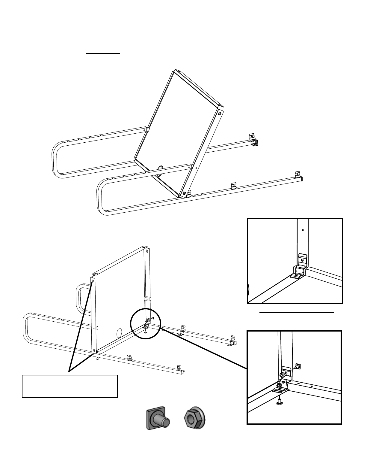
STEP 1
Position the top shelf onto the rear legs making sure the leg brackets are to inside of
the shelf. LOOSELY secure the shelf to the legs using screws (AA) and bolts (BB).
These side holes are used for
installing the handle. Leave one of
the sides open to install the handle.
AA
BRACKET TO THE INSIDE
BB
2
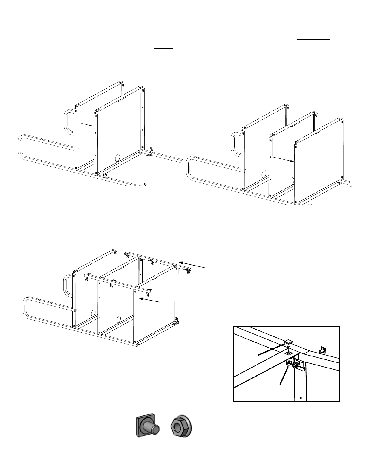
STEP 2
Slide the middle and bottom shelves onto the rear legs. Slide the front legs on. LOOSELY
install hardware to top shelf corner ONLY, remembering to leave access for the handle.
Slide on middle shelf.
Slide on bottom shelf.
Slide on front legs.
AA
AA
BB
INSTALL HARDWARE TO TOP
SHELF CORNER ONLY, OMIT
HANDLE SIDE
BB
3
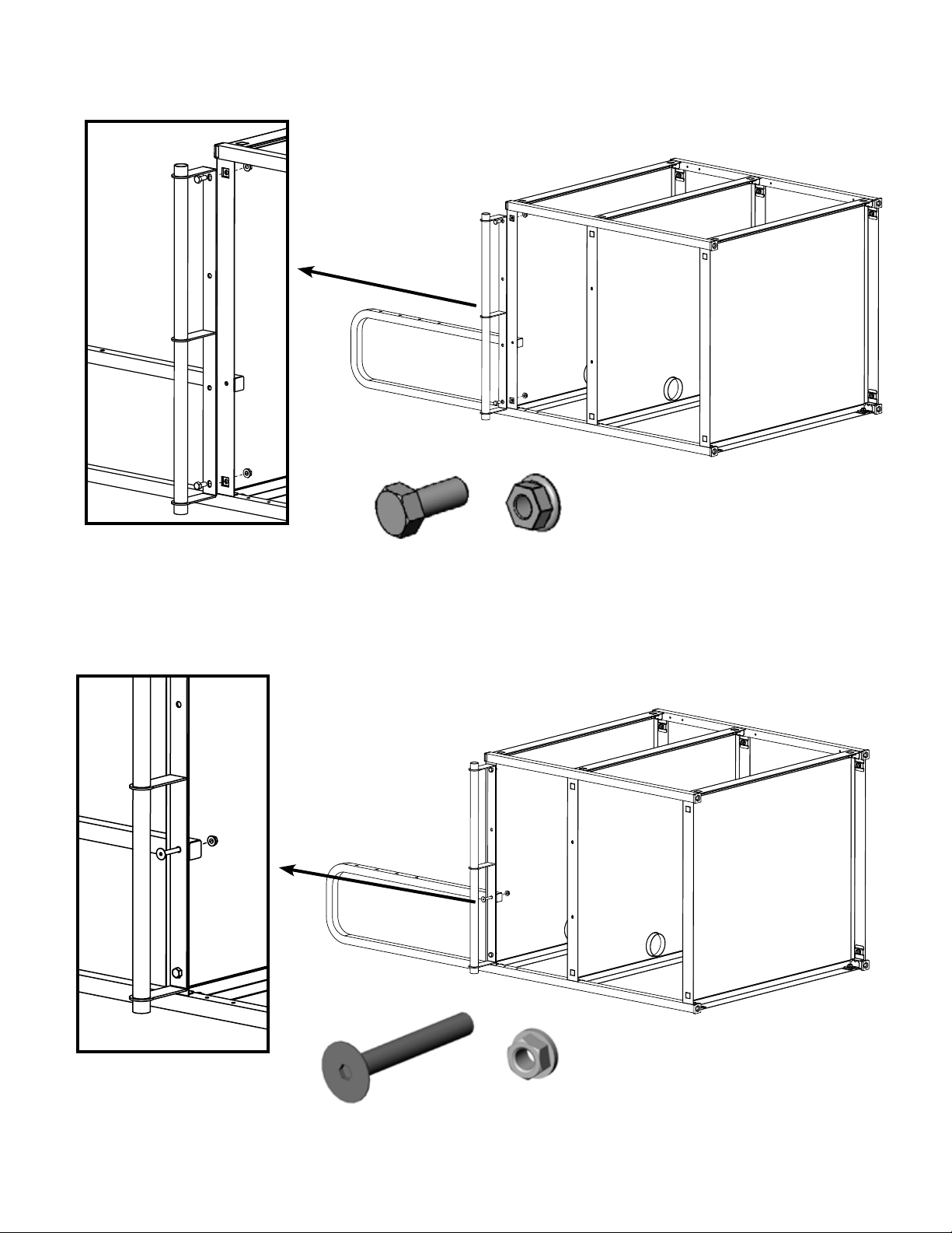
STEP 3
Install handle to either side of the cart using bolts (GG) and nuts (BB).
GG
BB
STEP 4
Secure tube and top shelf together using screws (HH) and nuts (II).
HH
II
4

STEP 5
Position each side panel under the middle shelf and hook it’s bottom ange under the bottom shelf as
shown. LOOSELY install hardware to each corner with bolts (AA) and nuts (BB). Carefully rotate cart
onto it’s back and install rear panel just like side panels.
Side Panel
AA
BB
INSTALL HARDWARE TO
EACH CORNER
AA
Rear Panel
BB
NOW TIGHTEN ALL CART CORNER HARDWARE
5

STEP 6
Install door stop to bottom shelf using screws (CC) and nuts (DD).
CC
DD
STEP 7
Attach a handle to each door with screws (EE). Then install each door between the middle and bottom
shelves with screws (FF). NOTE: Adjustments to the door stop may need to be done.
EE
FF
6

STEP 8
Push a caster into each leg insert. To ensure casters are securely in place, a rubber mallet may be used
to tap them in place. NOTE: The locking casters MUST be installed on the same side as the handle.
STEP 9
Attach the monitor bracket onto the front of the rear leg tubes as shown using bolts (JJ) and nuts (KK).
JJ
KK
7

SKIP TO STEP 15 IF YOUR CART DOES NOT HAVE A SHELF
STEP 10
Attach each shelf bracket under the top shelf as shown using screws (FF).
Make sure the bracket
cutouts face this way, if not
the bracket will be installed
upside down.
FF
STEP 11
Install the outer slide onto the shelf bracket by sliding TAB 1 into CUTOUT A and TAB 2 into CUTOUT B.
The pull out shelf should be installed opposite of the handle.
TAB 1
TAB 2
CUTOUT A
This tab determines
where the shelf will
slide out from.
Each cart bracket has
additional cutouts to allow
the shelf to pull out from
either side of the cart.
CUTOUT B
NOTE: Some bend in the bracket is ok as the slides and shelf will take care of that once
they are installed.
8

STEP 12
Install each inner slide into the outer slides. NOTE: Push inner slide in all the way until it snaps in.
STEP 13
Extend the slides to the positioning shown.
9

STEP 14
Install the pull out shelf by sliding CUTOUT 1 into TAB 1 and CUTOUT 2 into TAB 2.
TAB 1
CUTOUT 1
CUTOUT 2
TAB 2
10

STEP 15
Attach both hook bars onto the back of your monitor using the mounting holes built into the case. A
courtesy hardware pack has been provided with several metric screw sizes. You may need to purchase
additional metric screws from your local hardware store for odd shaped monitors.
TOP
BOTTOM
STEP 16
With someone’s help, hook your monitor onto the bracket as shown. (Monitor removed from picture for clarity.)
MONITOR NOT
SHOWN FOR CLARITY
11

STEP 17
Attach the stop brackets to the hook bars as shown with security screws (LL) using the
driver bit provided.
LL
STEP 18
Center your monitor horizontally and then tighten in place with screws (MM).
MM
CENTER MONITOR HORIZONTALLY THEN SECURE
Part # 031-8691
Rev. 05.11.11 CZ
12
 Loading...