

Bretford FLIP TOP QUATTRO TABLE Assembly Instructions Manual

FLIP TOP
QUA TTRO T ABLES
Assembly Instructions
Parts List
Qty. Part No. Description
4 010-351 1 Corner Ties
4 017-0686 Bottom Legs
4 017-1026 Top Legs
1 * * Worksurface & Flip Up Top Assembly
**Part number varies with each size table.
Hardware List
Qty. Part No. Description
8 030-0396 3/8-16 x 1/2" Set Screws
4 030-0852 5/16-18 x 1-1/4" Hex Flange Cap Screws
4 015-0084 3/8-16 Glides
** 030-0383 #10 x 1/2" Truss Head Screws
**(3) For 30" or 36" Cord Bins
**(5) For 42" or 48" Cord Bins
**(7) For 60" Cord Bins
**(9) For 72" or 84" Cord Bins
Tools Required
Phillips Screwdriver
Allen Wrench
Adjustable Wrench
SAFETY WARNING
Note: TWO PERSON
ASSEMBLY REQUIRED
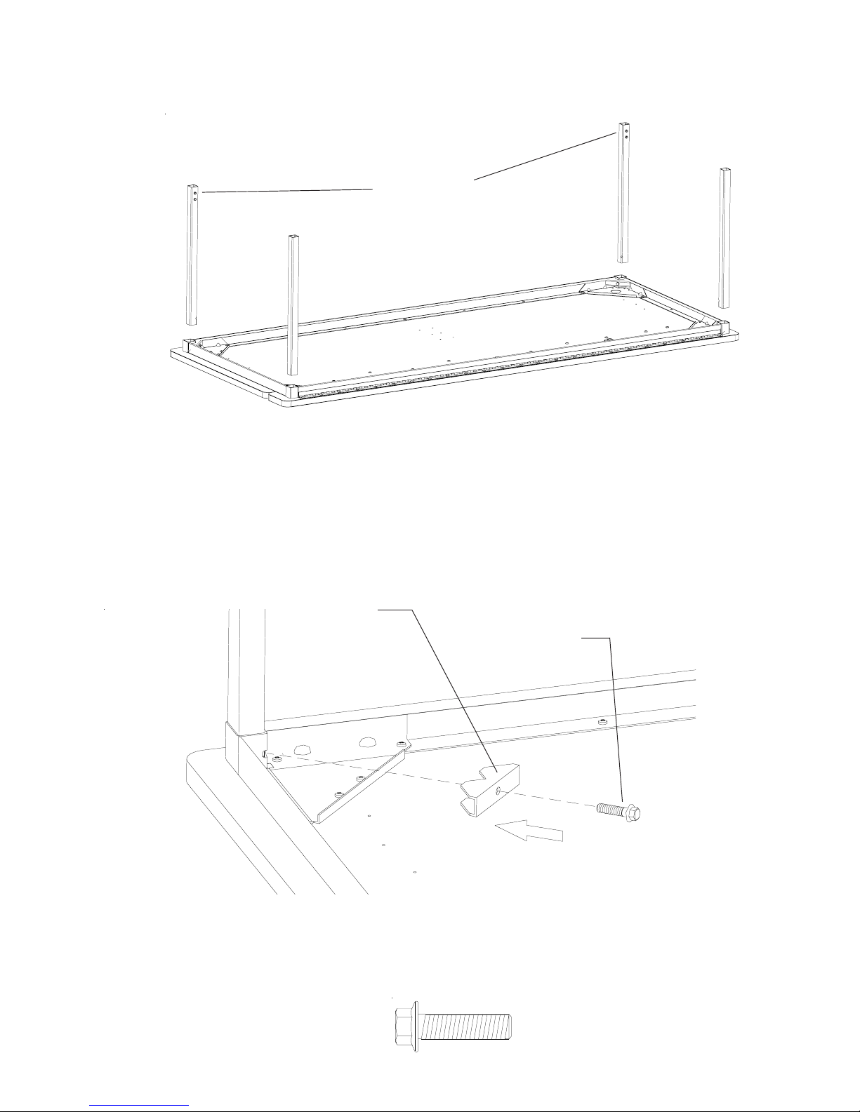
All Leg
Holes Face
Inward
STEP 1
Lay wood top on a carpeted surface as shown. Insert a leg into each corner.
The holes on the front legs should face to the inside of the table. The back leg
holes can face each other or to the inside of the table which ever you prefer.
NOTE: The view shown has all leg holes facing into the table.
Corner tie
010-351 1
5/16-18 x 1-1/4"
030-0852
STEP 2
Attach legs with 5/16-18 x 1-1/4" Hex Flange Cap screws
(030-0852) and corner ties (010-351 1). Tighten all screws.
 Loading...