

Bretford ec7000 Assembly Instructions Manual
EC7000
Computer Workstation
with CPU Holder
Assembly Instructions
PARTS LIST HARDWARE LIST
Qty Part# Description
1 010-3056 CPU Top Bracket
1 010-3057 CPU Bottom Bracket
1 010-3058 CPU Side Bracket
1 010-3059 CPU Locking Slide Bracket
4 017-0377 Front and Rear Leg
1 022-1993 Top Assembly
1 022-1991 Wire Tray Assembly
1 022-1992 H-Frame Assembly
2 015-0002 4" Casters w/o Lock
2 015-0003 4" Casters w/ Lock
TOOLS REQUIRED
Phillips Screwdriver
Adjustable Wrench
Rubber Mallet
Hex Wrench (provided)
Ref Qty Part# Description
AA 4 030-0200 1/4-20 x 1" Hex head Screw
BB 4 030-0120 1/4-20 Square Nut
CC 8 030-0383 #10 x 1/2" Truss Head Screw
DD 3 030-0147 1/4-20 x 1 1/4" Machine Screw
EE 6 030-0148 1/4-20 Acorn Nut
FF 2 030-0325 1/4-20 x 1/2" Combo Truss Screw
GG 1 030-0474BK 1/4-20 x 7/8" Flat Hd. Allen Screw
HH 1 SC1047BK 1/4-20 x 37.5mm Connector Bolt
II 2 030-0305 7/8" Washer
JJ 3 030-0207 1/4-20 Flanged Hex Nut
KK 4 030-0272 1/4-20 x 1/2" Carriage Bolt
LL 4 030-0306 1" Washer
1 010-1106 Hex Wrench
1 HK1020 Standard Allen Wrench
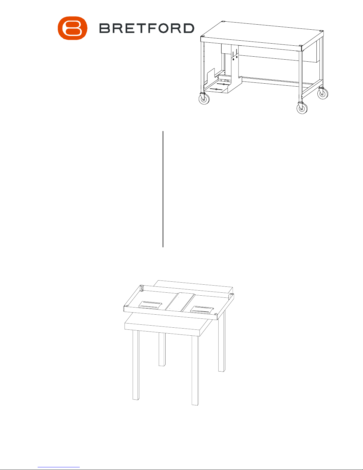
Lay the top shelf on a table so that the square brackets and
stiffener face up and the 4 corners hang over the table as shown.
NOTE: The logo label represents the front edge of the top.
FRONT EDGE
STEP 1
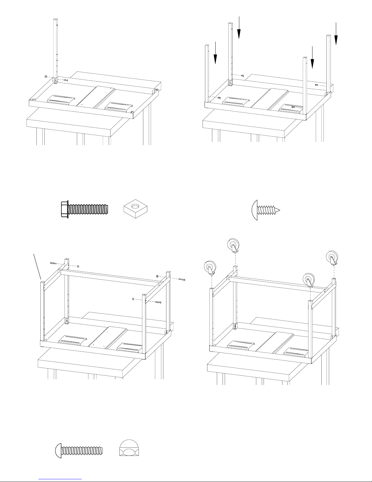
STEP 2 STEP 3
Position one leg into the square bracket so that the
capped end is flush with the top of the shelf and the
holes face in as shown. LOOSELY attach with screws
(AA) and nuts (BB). Attach the remaining 3 legs in the
same manner.
Insert a self tapping screw (CC) approximately 3/4 of the
way into the first hole in each leg. Slide each leg down so
that the square bracket rests on the shaft of the self
tapping screw, not the head of the screw. TIGHTEN ALL
SHELF HARDWARE.
LEAVE OPEN FOR
CPU HOLDER (It can
be the right or left side )
AA
SHORTER SIDE
STEP 4
BB
CC
Slide the H-frame between the legs as shown. The
shorter side faces the rear. Secure the frame to the legs
using screws (DD) and nuts (EE) as shown. NOTE: One
leg on the front side DOES NOT GET HARDWARE, this is
left open for the CPU holder. You decide whether to leave
the right or left side open.
DD
STEP 5
Insert each caster into the legs. If casters do not insert
easily, use a rubber mallet to tap each caster in place.
Make sure casters are SECURELY seated into the legs
before stand unit upright.
EE
 Loading...