

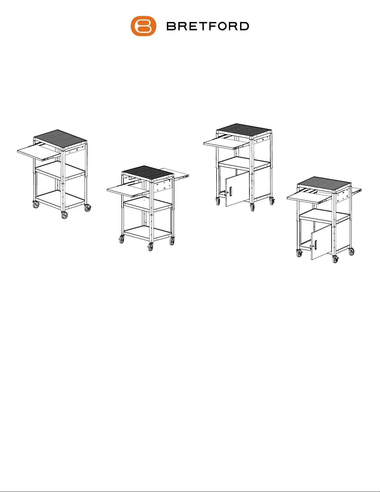
A2642NS CA2642NS
A2642DNS CA2642DNS
ADJUSTABLE CART WITH OR WITHOUT CABINET
SINGLE OR DOUBLE PULL OUT SHELVES
Assembly Instructions
Parts List
Qty Part # Description
1 022-2813 Top Section for Single Shelf Models
022-3087 Top Section for Double Shelf Models
1 022-1099 Bottom Section for Open Shelf Models
022-1252 Bottom Section for Cabinet Models
1 010-5773 Notebook Pull Out Shelf (2 for Double Shelf Models)
1 030-1468 Left Outer Slide (2 for Double Shelf Models)
1 030-1470 Right Outer Slide (2 for Double Shelf Models)
2 030-1471 Inner Slides (4 for Double Shelf Models)
1 RM1824 18” x 24” Rubber Mat
Casters 4” Models = (2) 015-0002 w/o Brake & (2) 015-0003 w/Brake
5” Models = (2) 015-0017 w/o Brake & (2) 015-0018 w/Brake
Hardware List
Ref Qty Part # Description
AA 4 030-0253 1/4-20 x 3/4” Combo Screws
BB 4 030-0120 1/4-20 Square Nuts
1 030-0368 M111 Replacement Key Set
(included with Cabinet Cart Models Only)
1
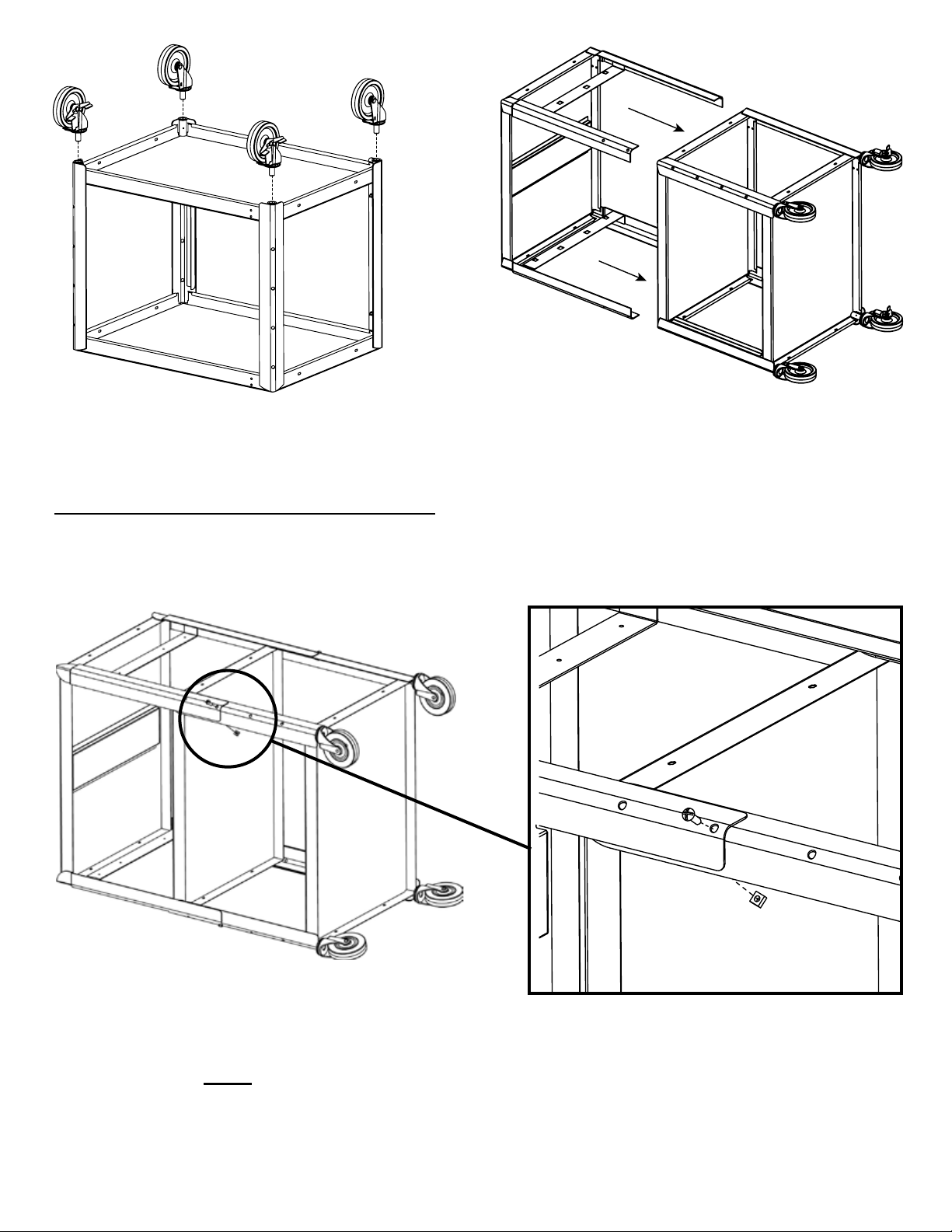
STEP 1
Turn bottom section over and push each caster into each
of the corner sockets. If casters do not insert easily a
rubber mallet may be used to tap the casters in place.
MAKE SURE CASTERS ARE SECURELY IN PLACE.
STEP 2
Lay both top and bottom sections on their sides. Slide
the top section over the bottom section as shown.
STEP 3
Attach legs together using screws (AA) and nuts (BB) as shown.
NOTE: Carts have height adjustments at 4” increments. The single shelf models
range from 26” to 42” and the double shelf models range from 34” to 42”.
2

This tab determines where the
shelf will slide out from.
Each cart bracket has additional
cutouts to allow the shelf to pull
out from either side of the cart.
Based this slide position
shown, the shelf will extend
out on this side of the cart.
TAB 2
TAB 1
CUTOUT B
CUTOUT A
STEP 4
Install the outer slide onto the cart bracket by sliding
TAB 1 into CUTOUT A and TAB 2 into CUTOUT B.
NOTE: Some bend in the bracket is ok as the slides and
shelf will take care of that once they are installed.
IMPORTANT NOTE: Double shelf “DNS” models should have pull
out shelves installed to pull out opposite from one another.
3

STEP 5
Install each inner slide into the outer slides. NOTE:
Push inner slide in all the way until it snaps in.
STEP 6
Extend the slides to the positioning shown.
4

CUTOUT 2
TAB 1
TAB 2
CUTOUT 1
STEP 7
Install the pull out shelf by sliding CUTOUT 1 into TAB 1 and CUTOUT 2 into TAB 2.
Part # 031-7755
Rev. 01.20.11 CZ
5
 Loading...