

Page 1
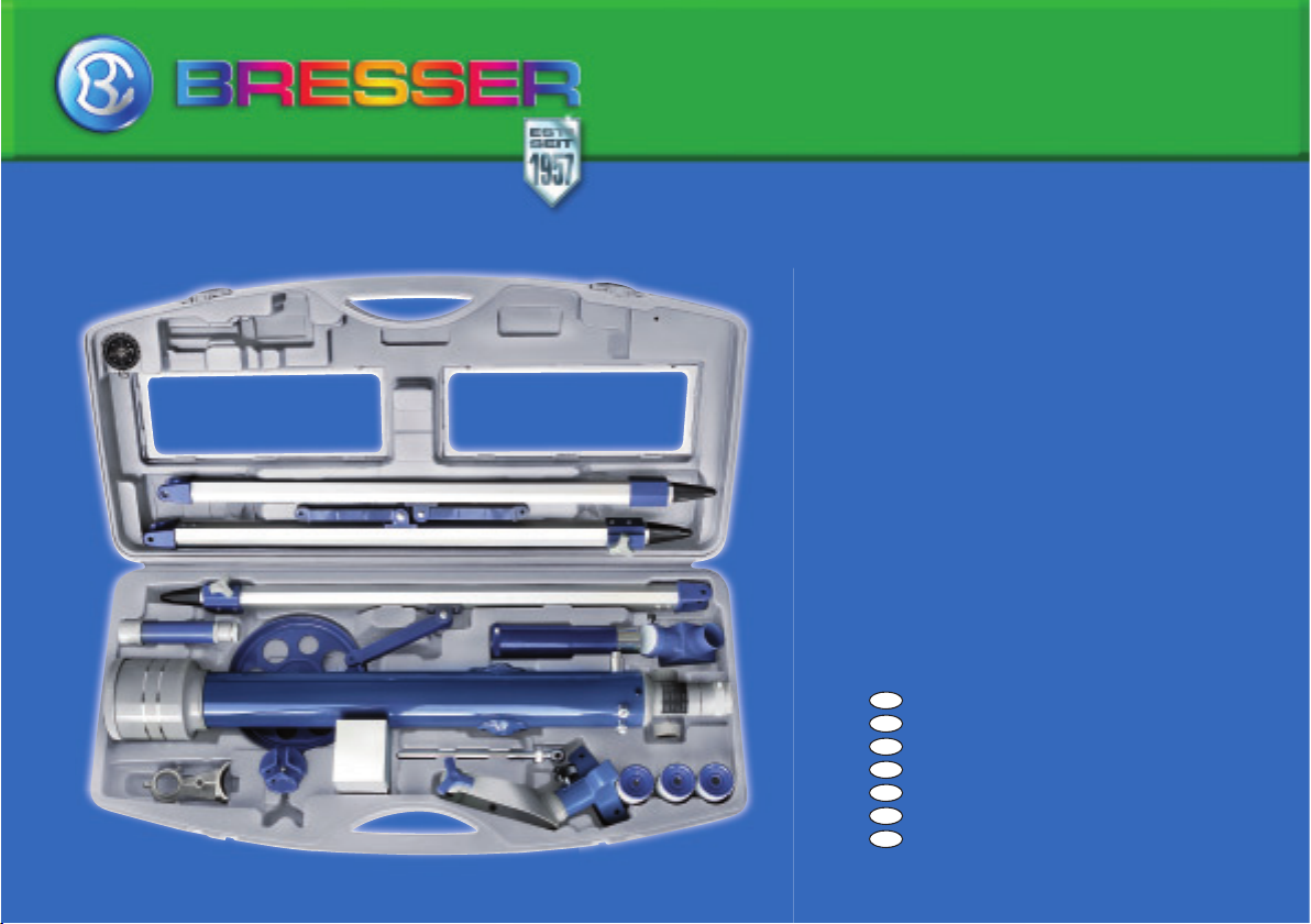
Telescope 60/700
Art. No. 88-43100
DE
Bedienungsanleitung
GB
Operating Instructions
FR
Mode d’emploi
NL
Handleiding
IT
Istruzioni per l’uso
ES
Instrucciones de uso
PT
Manual de utilização
Page 2

DE Bedienungsanleitung ..................................................................4
GB
Operating Instructions ..............................................................14
FR
Mode d’emploi ...........................................................................24
NL
Handleiding ................................................................................34
IT
Istruzioni per l’uso .....................................................................44
ES
Instrucciones de uso ................................................................54
PT
Manual de utilização .................................................................64
Page 3
j
F
e
d
G
c
1@
B
H
1%
1*
i
1!
1#
1$
1(
1^
1)
1&
F
2)
E
2!
2@
Page 4

Liebe Eltern,
dieses Produkt ist ideal für Kinder, die ihre
Welt auf neue Weise erkunden möchten. Es
ist daher einfach zu bedienen und zu pfl egen,
es ist robust und sieht gut aus.
Wichtiger als all das ist Ihnen und uns freilich
der sichere Gebrauch. So haben wir schon
bei der Herstellung darauf geachtet, dieses
Produkt auch für die Benutzung durch Kinder
so sicher wie möglich zu machen. Trotzdem
können gewisse Gefahrenquellen nie gänzlich ausgeschlossen werden. Schließlich handelt es sich hierbei nicht um ein Spielzeug im
herkömmlichen Sinne, sondern um viel mehr:
Dieses Produkt ist ein vollwertiges optisches
Instrument, mit dem Kinder die Welt erleben,
forschen und experimentieren können.
Deshalb bitten wir Sie an dieser Stelle um Ihre
Mitwirkung. Diese Bedienungsanleitung ist in
wesentlichen Teilen zwar für Kinder geschrieben, lesen Sie sie aber bitte trotzdem mit Ihrem Kind gemeinsam durch und beantworten
Sie seine Fragen. Erklären Sie selbst Ihrem
Kind die möglichen Gefahren.
Unter der Rubrik „Warnhinweise“ werden
mögliche Gefahrenquellen genannt, die im
Umgang mit diesem Gerät entstehen können.
Nehmen Sie alle Einstellungen am Gerät ge-
4
meinsam mit Ihrem Kind vor, lassen Sie das
Kind damit nie unbeaufsichtigt!
Wir wünschen Ihnen und Ihrem Kind viel Freude und spannende Entdeckungen.
Ihr Bresser-Team
------------------------------
Lieber Junior-Forscher!
Liebe Junior-Forscherin!
Du hast dieses Produkt gekauft (oder als Geschenk bekommen), wozu ich dir gratulieren
möchte.
Beim Lesen dieser Bedienungsanleitung wirst
du sicherlich erstaunt sein, wie vielseitig das
Produkt einsetzbar ist und was mal damit alles
entdecken gibt.
Überzeuge dich selbst davon und tauche ein
in die Welt der Naturerlebnisse und Entdeckungen.
Es macht ungeheuer viel Spaß und ist wirklich spannend, mit diesem Produkt die Welt
zu erleben.
Bevor du es aber benutzt, solltest du dir zuerst diese Bedienungsanleitung gut durchle-
sen. Es gibt nämlich einige wichtige Punkte,
die du wissen solltest, bevor du die ersten
Beobachtungen damit unternimmst.
Besonders aufmerksam lies bitte die „Warnhinweise“ durch! Benutze das Produkt nur
wie es in dieser Anleitung beschrieben ist,
damit nicht versehentlich Verletzungen oder
Schäden passieren. Bewahre diese Anleitung
zum späteren Nachlesen auf. Wenn Du das
Gerät weitergibst oder verschenkst, gib auch
diese Anleitung mit.
Und nun wünsche ich dir viel Spaß beim Forschen und Entdecken!
Deine Pia
Page 5
GEFAHR für Ihr Kind!
Schauen Sie mit diesem Gerät niemals
direkt in die Sonne oder in die Nähe
der Sonne. Es besteht
FAHR!
Kinder sollten das Gerät nur unter Aufsicht
benutzen. Verpackungsmaterialien (Plastiktüten, Gummibänder, etc.) von Kindern fernhalten! Es besteht
BRANDGEFAHR!
Setzen Sie das Gerät – speziell die Lin-
sen – keiner direkten Sonneneinstrahlung aus! Durch die Lichtbündelung könnten
Brände verursacht werden.
GEFAHR von Sachschäden!
Bauen Sie das Gerät nicht auseinan-
der! Wenden Sie sich im Falle eines
Defekts bitte an Ihren Fachhändler. Er nimmt
mit dem Service-Center Kontakt auf und kann
das Gerät ggf. zwecks Reparatur einschicken.
Setzen Sie das Gerät keinen Temperaturen
über 60° C aus!
HINWEISE zur Reinigung
ERSTICKUNGSGEFAHR!
Reinigen Sie die Linsen (Okulare
und/oder Objektive) nur mit dem
beiliegeden Linsenputztuch oder
ERBLINDUNGSGE-
mit einem anderen weichen und fusselfreien
Tuch (z.B. Microfaser) ab. Das Tuch nicht zu
stark aufdrücken, um ein Verkratzen der Linsen zu vermeiden.
Zur Entfernung stärkerer Schmutzreste befeuchten Sie das Putztuch mit einer BrillenReinigungsfl üssigkeit und wischen Sie damit
die Linsen mit wenig Druck ab.
Schützen Sie das Gerät vor Staub und Feuchtigkeit! Lassen Sie es nach der Benutzung –
speziell bei hoher Luftfeuchtigkeit – bei Zimmertemperatur einige Zeit akklimatisieren, so
dass die Restfeuchtigkeit abgebaut werden
kann. Setzen Sie die Staubschutzkappen auf
und bewahren Sie es in der mitgelieferten Tasche auf.
SCHUTZ der Privatsphäre!
Das Teleskop ist für den Privatgebrauch gedacht. Achten Sie die
Privatsphäre Ihrer Mitmenschen –
schauen Sie mit diesem Gerät zum Beispiel
nicht in Wohnungen!
ENTSORGUNG
Entsorgen Sie die Verpackungsmate-
rialien sortenrein. Informationen zur
ordnungsgemäßen Entsorgung erhalten Sie
beim kommunalen Entsorgungsdienstleister
oder Umweltamt.
DE
Page 6
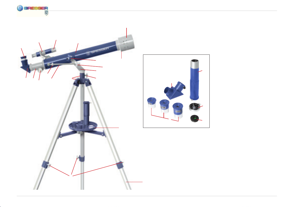
Aus diesen Teilen besteht dein Teleskop
Der Aufbau
1 Höhenfeineinstellung
2 Fokussiertrieb
3 Fokussierrohr
4 Zenitspiegel
5 Okulare
6 Sucherfernrohr-Halterung
7 Sucherfernrohr
8 Fernrohr (Teleskop-Tubus)
9 Sonnenblende
10 Objektivlinse
11 Feststellschraube
12 Schraube zur Höheneinstellung
13 Joch
14 Azimut-Sicherung
15 Stativkopf
16 Zubehörablage
17 Stativbein
18 Flügelschraube
19 Schraube
20 Okularverlängerung
21 Kompass
22 Mondfi lter
6
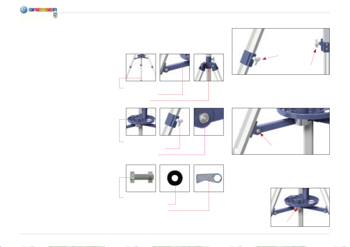
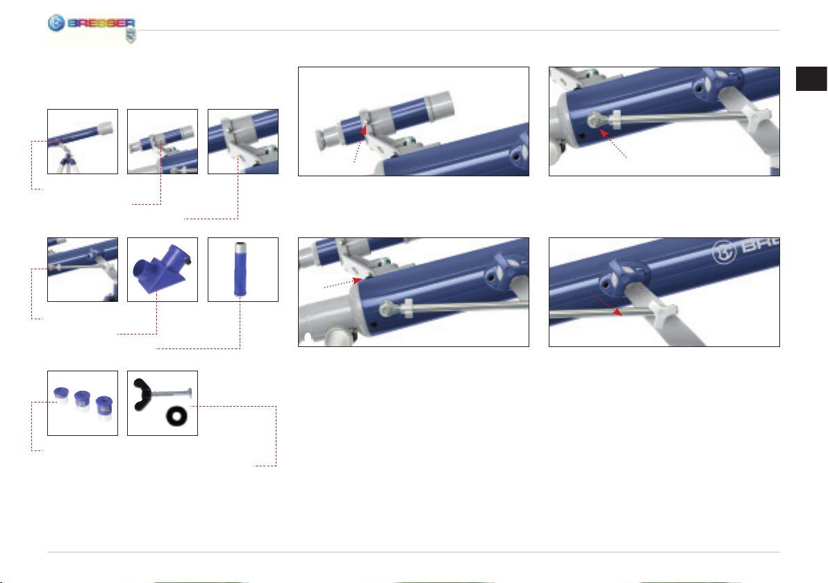
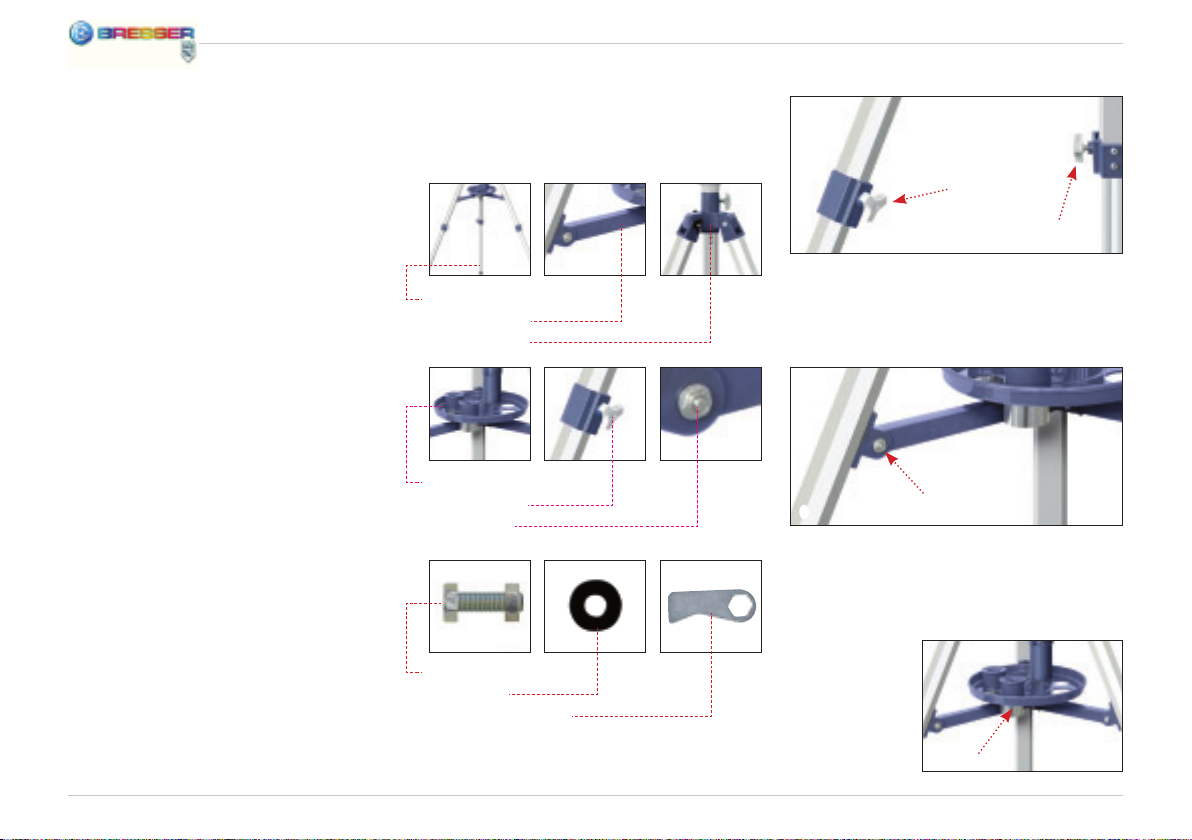
Du beginnst mit dem Aufbau des Stativs und
benötigst dazu folgende Teile:
Stativbeine u. Streben
Mittelstrebe
Stativkopf
Zubehörteller
Flügelschrauben
Flügelmuttern
Kleine Schrauben
Unterlegscheiben
Schraubwerkzeug
b
Befestige die Stativbeine mit Hilfe der Flügelschrauben, Unterlegscheiben und Flügelmuttern am Stativkopf.
c
Bringe die Mittelstrebe mit den kleinen
Schrauben an den Stativbein-Streben an.
– Wichtig! Der goldene Kreis der Mittelstrebe
muss nach oben zeigen.
Schraube zum
Schluss den
Zubehörteller
auf der Mittelstrebe fest.
d
Page 7
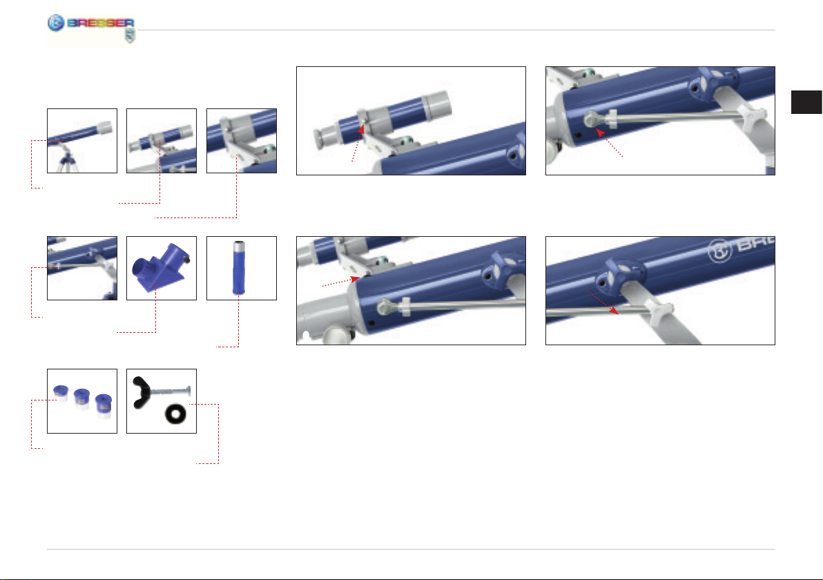
Jetzt wendest Du Dich dem Teleskop-Tubus
zu und fi ndest noch folgende Teile vor:
DE
Teleskop-Tubus
Sucherfernrohr
Sucherfernrohr-Halterung
Höhenfeineinstellung u. Schrauben
Zenitspiegel
Okularverlängerung
Okulare
Wendelschrauben u. Unterlegscheiben
b
Zuerst musst Du das Sucherfernrohr mit der
Sucherfernrohr-Halterung verbinden (einsetzen und mit drei Schräubchen festdrehen).
c
Am Teleskop-Tubus erkennst Du zwei herausragende Gewinde. Dort schraubst Du die Halterung mit dem Sucherfernrohr fest.
d
Als Nächstes schraubst Du die Höhenfeineinstellung an dem herausragenden silbernen
Metallstutzen des Teleskop-Tubus an.
E
Nun wird es schwierig! Am besten lässt Du
Dir von jemandem helfen. Du musst den Teleskop-Tubus mit dem Stativ verbinden. Nimm
dazu die Wendelschrauben mit den Unterlegscheiben und schraube den Tubus am Stativkopf an.
7
Page 8
Azimutale Montierung
Azimutale Montierung bedeutet nichts anderes, als dass Du Dein Teleskop auf- und
abwärts und nach links und rechts bewegen
kannst, ohne das Stativ zu verstellen.
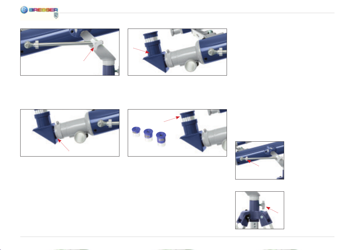
F
Bringe die Feststellschraube für die Höhenfeineinstellung am Joch des Stativkopfes an.
G
Montiere jetzt den Zenitspiegel am Fokussierrohr des Tubus.
8
H
Wenn Du die Okularverlängerung nutzen
möchtest, befestige sie am Zenitspiegel.
I
Als Letztes wählst Du eines der drei Okulare
und befestigst es am Zenitspiegel (oder an
der Okularverlängerung).
Mit Hilfe der Azimut-Sicherung und der
Schrauben für die Höhenfeineinstellung
kannst Du Dein Teleskop feststellen, um ein
Objekt zu fi xieren (d. h. fest anzublicken).
Mit Hilfe der Höhenfeineinstellung bewegst
Du das Teleskop langsam auf- und abwärts.
Und nach Lösen der Azimut-Sicherung kannst
Du es nach links und nach rechts schwenken.
Höhenfeineinstellung
j
Azimut-Sicherung
1)
Page 9

Vor der ersten Beobachtung
Bevor du zum ersten Mal etwas beobachtest, musst du das Sucherfernrohr und das
Fernrohr aufeinander abstimmen. Du musst
das Sucherfernrohr so einstellen, dass du
dadurch das gleiche siehst wie durch das
Okular des Fernrohrs. Nur so kannst du bei
deinen Beobachtungen das Sucherfernrohr
zum groben Anpeilen von Objekten benutzen,
bevor du sie vergrößert durch das FernrohrOkular betrachtest.
1!
Du solltest nun beim Blick durch das Okular
den gleichen Bildausschnitt wie beim Blick
durch das Sucherfernrohr (aber natürlich auf
dem Kopf stehend) sehen.
Wichtig: Erst wenn beide Bildausschnitte
gleich sind, sind Sucherfernrohr und Fernrohr richtig aufeinander abgestimmt.
DE
Sucherfernrohr und das Fernrohr aufeinander abstimmen
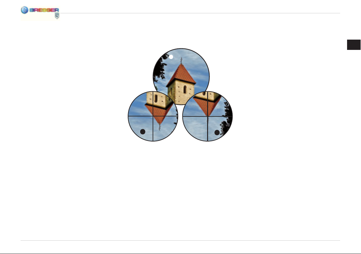
Schaue durch das Okular des Fernrohrs und
peile ein gut sichtbares Objekt (z.B. einen
Kirchturm) in einiger Entfernung an. Stelle es
mit dem Scharfeinstellungsrad scharf wie es
in Abb. 11 gezeigt wird.
Wichtig: Das Objekt muss mittig im Blickfeld
des Okulars zu sehen sein.
Tipp: Löse die Fixierschrauben für die Höhenfeineinstellung und die Vertikalachse, um
das Fernrohr nach rechts und links oder nach
oben und unten bewegen zu können. Wenn
du das Objekt richtig im Blickfeld hast, kannst
du die Fixierschrauben wieder anziehen, um
die Position des Fernrohrs zu fi xieren.
a
b
1@
Als nächstes schaust du durch das Sucherfernrohr. Du siehst das Bild deines angepeilten Objekts in einem Fadenkreuz. Das Bild
steht auf dem Kopf.
Hinweis: Das Bild, das du durch das Sucherfernrohr siehst, steht auf dem Kopf, weil das
Bild durch die Optik umgekehrt wird. Das ist
völlig normal und kein Fehler.
Falls das Bild, das du durch das Sucherfernrohr siehst, nicht genau mittig im Fadenkreuz
steht (Abb. 12a), musst du an den Justierschrauben für das Sucherfernrohr drehen.
Drehe solange an den Schrauben, bis das
Bild mittig im Fadenkreuz steht (Abb. 12b).
9
Page 10
Welches ist das richtige Okular?
Wichtig ist zunächst, dass du für den Beginn deiner Beobachtungen immer ein Okular mit der
höchsten Brennweite wählst. Du kannst dann nach und nach andere Okulare mit geringerer
Brennweite wählen. Die Brennweite wird in Millimeter angegeben und steht auf dem jeweiligen
Okular. Generell gilt: Je größer die Brennweite des Okulars, desto niedriger ist die Vergrößerung! Für die Berechnung der Vergrößerung gibt es eine einfache Rechenformel:
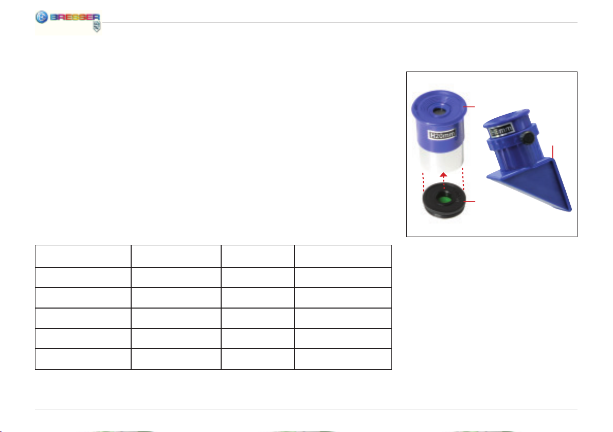
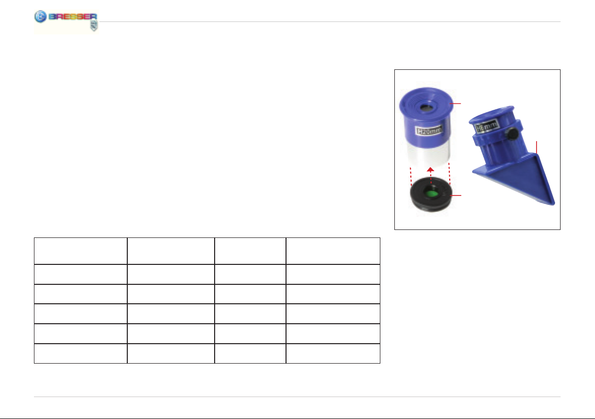
Verwendung des Mondfi lters
F
Brennweite des Fernrohrs : Brennweite des Okulars = Vergrößerung
Du siehst: Die Vergrößerung ist auch von der Brennweite des Fernrohrs abhängig. Dieses Teleskop beinhaltet ein Fernrohr mit 700 mm Brennweite. Daraus ergibt sich anhand der Rechenformel folgende Vergrößerung, wenn du ein Okular mit 20 mm Brennweite verwendest:
700 mm : 20 mm = 35fache Vergrößerung
Zur Vereinfachung habe ich dir hier eine Tabelle mit einigen Vergrößerungen
zusammengestellt:
Teleskop-Brennweite Okular-Brennweite Vergrößerung mit 1,5x Umkehrlinse
700 mm 24 mm 29x 43,5x
700 mm 20 mm 35x 52,5x
700 mm 12,5 mm 56x 84x
700 mm 6 mm 116x 174x
700 mm 4 mm 175x 262,5x
10
E
2@
1%
Wenn dir das Bild des Mondes irgendwann zu
hell ist, dann kannst du den grünen Mondfi lter
von unten in das Gewinde des Okulars einschrauben. Das Okular kannst du dann ganz
normal in den Zenitspiegel einsetzen.
Das Bild das du nun beim Blick durch das
Okular siehst, ist grünlich. Die Helligkeit des
Mondes wird dadurch verringert, das Beobachten ist angenehmer.
Page 11

1. Technische Daten:
• Bauart: achromatischer Refraktor
• Brennweite: 700 mm
• Objektivdurchmesser: 60 mm
• Sucher: 5x24
• Montierung: azimutal auf Stativ
2. Mögliche Beobachtungsobjekte:
Nachfolgend haben wir für dich einige sehr
interessante Himmelskörper und Sternhaufen
ausgesucht und erklärt. Auf den zugehörigen
Abbildungen am Ende der Anleitung kannst du
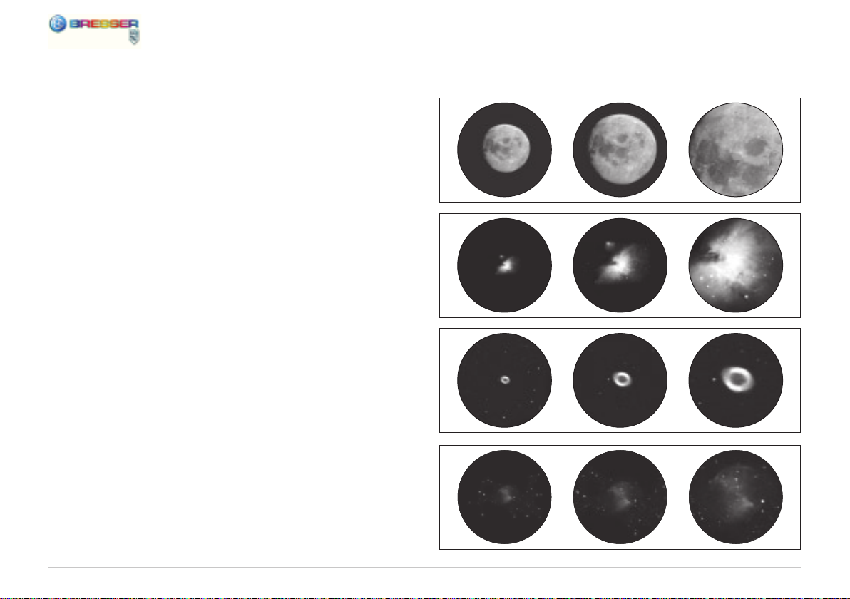
sehen, wie du die Objekte durch dein Teleskop mit den mitgelieferten Okularen bei guten
Sichtverhältnissen sehen wirst:
Der Mond
Der Mond ist der einzige natürliche Satellit der
Erde. (Abb. 13)
Durchmesser: 3.476 km
Entfernung: ca. 384.401 km
Der Mond ist seit prähistorischer Zeit bekannt.
Er ist nach der Sonne das zweithellste Objekt
am Himmel. Da der Mond einmal im Monat
um die Erde kreist, verändert sich ständig der
Winkel zwischen der Erde, dem Mond und
der Sonne; man sieht das an den Zyklen der
Mondphasen. Die Zeit zwischen zwei aufeinander folgenden Neumondphasen beträgt
etwa 29,5 Tage (709 Stunden).
Orion-Nebel (M 42)
M 42 im Sternbild Orion (Abb. 14)
Rektaszension: 05:32,9 (Stunden : Minuten)
Deklination: –05:25 (Grad : Bogenminuten)
Entfernung: 1.500 Lichtjahre
Mit einer Entfernung von etwa 1500 Lichtjahren ist der Orion-Nebel (Messier 42, kurz M
42) der hellste diffuse Nebel am Himmel – mit
dem bloßen Auge sichtbar, und ein lohnendes
Objekt für Teleskope in allen Größen, vom
kleinsten Feldstecher bis zu den größten erdgebundenen Observatorien und dem Hubble
Space Telescope.
Es handelt sich um den Hauptteil einer weit
größeren Wolke aus Wasserstoffgas und
Staub, die sich mit über 10 Grad gut über die
Hälfte des Sternbildes Orion erstreckt. Die
Ausdehnung dieser gewaltigen Wolke beträgt
mehrere hundert Lichtjahre.
Ringnebel in der Leier (M 57)
M 57 im Sternbild Leier (Abb. 15)
Rektaszension: 18:51,7 (Stunden : Minuten)
Deklination: +32:58 (Grad : Bogenminuten)
Entfernung: 2.000 Lichtjahre
Der berühmte Ringnebel M 57 im Sternbild
Leier wird oft als der Prototyp eines planetarischen Nebels angesehen; er gehört zu
den Prachtstücken des Sommerhimmels der
Nordhalbkugel. Neuere Untersuchungen haben gezeigt, dass es sich aller Wahrscheinlichkeit nach um einen Ring (Torus) aus hell
leuchtender Materie handelt, die den Zentralstern umgibt (nur mit größeren Teleskopen
sichtbar), und nicht um eine kugel- oder ellipsoidförmige Gasstruktur.
11
DE
Page 12

Würde man den Ringnebel von der Seitenebene betrachten, würde er dem Hantel-Nebel
(M 27) ähneln. Wir blicken bei diesem Objekt
genau auf den Pol des Nebels.
f=20 mm f=12 mm f=4 mm
Hantel-Nebel im Füchslein (M 27)
M 27 im Sternbild Füchslein (Abb. 16)
Rektaszension: 19:59,6 (Stunden : Minuten)
Deklination: +22:43 (Grad : Bogenminuten)
Entfernung: 1.250 Lichtjahre
Der Hantel-Nebel (M 27) im Füchslein war der
erste planetarische Nebel, der überhaupt entdeckt worden ist. Am 12. Juli 1764 entdeckte
Charles Messier diese neue und faszinierende Klasse von Objekten. Wir sehen dieses
Objekt fast genau von seiner Äquatorialebene. Würde man den Hantel-Nebel von einem
der Pole sehen, würde er wahrscheinlich die
Form eines Ringes aufweisen und dem Anblick ähneln, den wir von dem Ringnebel M 57
kennen. Dieses Objekt kann man bereits bei
halbwegs guten Wetterbedingungen bei kleinen Vergrößerungen gut sehen.
Der Mond
1#
Orion-Nebel (M 42)
1$
Ringnebel in
der Leier (M 57)
1%
Hantel-Nebel
im Füchslein (M 27)
1^
12 12
Page 13

3. Kleines Teleskop-ABC
Was bedeutet eigentlich ...
Barlow-Linse:
Mit der Barlow-Linse, benannt nach ihrem
Erfi nder Peter Barlow (britischer Mathematiker und Physiker, 1776-1862), kann die
Brennweite eines Fernrohrs erhöht werden.
Abhängig vom jeweiligen Linsentyp ist eine
Verdopplung oder sogar Verdreifachung der
Brennweite möglich. Dadurch kann natürlich
auch die Vergrößerung gesteigert werden.
Siehe auch „Okular“.
Brennweite:
Alle Dinge, die über eine Optik (Linse) ein Objekt vergrößern, haben eine bestimmte Brennweite. Darunter versteht man den Weg, den
das Licht von der Linse bis zum Brennpunkt
zurücklegt. Der Brennpunkt wird auch als Fokus bezeichnet. Im Fokus ist das Bild scharf.
Bei einem Teleskop werden die Brennweiten
des Fernrohrs und des Okulars kombiniert.
Linse:
Die Linse lenkt das einfallende Licht so um,
dass es nach einer bestimmten Strecke
(Brennweite) im Brennpunkt ein scharfes Bild
erzeugt.
Okular:
Ein Okular ist ein deinem Auge zugewandtes
System aus einer oder mehreren Linsen. Mit
einem Okular wird das im Brennpunkt einer
Linse entstehende scharfe Bild aufgenommen
und nochmals vergrößert.
Für die Berechnung der Vergrößerung gibt es
eine einfache Rechenformel:
Brennweite des Fernrohrs : Brennweite des
Okulars = Vergrößerung
Du siehst: Bei einem Teleskop ist die Vergrößerung sowohl von der Brennweite des Okulars als auch von der Brennweite des Fernrohrs abhängig.
Daraus ergibt sich anhand der Rechenformel
folgende Vergrößerung, wenn du ein Okular mit 20 mm und ein Fernrohr mit 600 mm
Brennweite verwendest:
600 mm : 20 mm = 30fache Vergrößerung
Umkehrlinse:
Die Umkehrlinse wird vor dem Okular in den
Okularstutzen des Fernrohrs eingesetzt. Sie
kann durch die integrierte Linse die Vergrößerung durch das Okular zusätzlich steigern
(meist um das 1,5-fache). Das Bild wird – wie
der Name schon sagt – bei Verwendung einer
Umkehrlinse umgekehrt und erscheint aufrecht stehend und sogar seitenrichtig.
Vergrößerung:
Die Vergrößerung entspricht dem Unterschied
zwischen der Betrachtung mit bloßem Auge
und der Betrachtung durch ein Vergrößerungsgerät (z.B. Teleskop). Dabei ist die Betrachtung mit dem Auge einfach. Wenn nun
ein Teleskop eine 30-fache Vergrößerung hat,
so kannst du ein Objekt durch das Teleskop
30 Mal größer sehen als mit deinem Auge.
Siehe auch „Okular“.
Zenitspiegel:
Ein Spiegel, der den Lichtstrahl im rechten
Winkel umleitet. Bei einem geraden Fernrohr
kann man so die Beobachtungsposition korrigieren und bequem von oben in das Okular
schauen. Das Bild durch einen Zenitspiegel
erscheint zwar aufrecht stehend, aber seitenverkehrt.
13
DE
Page 14

Dear parents,
Dear junior researcher,
This product is ideal for children wanting to
explore their world in a completely new way.
The device is as such, easy to use and care
for, rugged and good-looking.
More important to you and of course to us is
that it is safe to use. During manufacture, we
made sure that this product is as safe it can
be for children to use. Some residual risk is,
however, unavoidable. This product, after all,
is not a toy in the usual sense but rather an
optical instrument that children can use to experiment, research and discover their world.
That‘s why we request your cooperation here.
These operating instructions were written
for children but please read them through
together with your child or children and answer his/her/their questions. Don‘t forget to
explain possible risks. These are summarised
under the heading „warnings“. Please adjust/
set up the device together with your child or
children and never allow any child to use any
of our optical products unsupervised.
We hope all users and their parents will enjoy
our products.
Your Bresser team
Congratulations on becoming the proud
owner of this product.
You‘ll be amazed when reading these
instructions just how much can be done and
explored with your new device.
Take a look and emerge yourself into the
adventurous world of nature and discovery.
It really is exciting and a lot of fun discovering
the world with this product.
Before you get started, read the operating
instructions fully, as there are a few things you
need to know to get the best out of your new
device.
The „Warnings“ should be read carefully.
Use the product exactly as per the operating
instructions to avoid any risk or injury. Keep
these instructions in a safe place for later
reference. If you give the device away or make
a present of it make sure these instructions
accompany it.
And now it just remains to say, „Have loads of
fun researching and discovering“
Pia
14
Page 15
RISK to your child!
Never look through this device directly
at or near the sun. There is a risk of
BLINDING YOURSELF!
Children should only use this device under supervision. Keep packaging materials (plastic
bags, rubber bands, etc.) away from children.
There is a risk of
Fire/Burning RISK!
Never subject the device - especially
the lenses - to direct sunlight. Light ray
concentration can cause fi res and/or burns.
RISK of material damage!
Never take the device apart. Please
consult your dealer if there are any
defects. The dealer will contact our service
centre and send the device in for repair if needed.
Do not subject the device to temperatures exceeding 60 C.
TIPS on cleaning
(e.g. micro-fi bre). Do not use excessive pressure - this may scratch the lens.
SUFFOCATION!
Clean the lens (objective and eyepiece) only with the cloth supplied
or some other soft lint-free cloth
Dampen the cleaning cloth with a spectacle
cleaning fl uid and use it on very dirty lenses.
GB
Protect the device against dirt and dust. Leave it to dry properly after use at room temperature. Then put the dust caps on and store
the device in the case provided.
RESPECT privacy!
This device is meant for private use.
Respect others‘ privacy – do not
use the device to look into other
people‘s homes, for example.
DISPOSAL
Dispose of the packaging material/s
as legally required. Consult the local
authority on the matter if necessary.
Page 16
Your telescope consists of these parts:
Assembly
1 Vertical fi ne adjustment
2 Focus wheel
3 Focus tube
4 Zenith mirror
5 Eyepiece
6 Finderscope holder
7 Finderscope
8 Telescope (Telescope tube)
9 Lens hood
10 Objective lens
11 Locking screw
12 Screw for the vertical fi ne
adjustment mechanism
13 Yoke
14 Azimuth Safety
15 Tripod head
16 Accessories caddy
17 Tripod leg
18 Wing screw
19 Screw
20 Eyepiece extender
21 Compass
22 Moon fi lter
16
First, you assemble the tripod. For this, you‘ll
need the following parts:
Tripod leg and spans
Division bar
Tripod head
Accessories plate
Wing screw
Wing nuts
Small screws
Washers
Assembly tools for
screws and nuts
b
Fix the tripod to the tripod head with the help
of the wing screw, washers and wing nuts.
c
Attach the middle span to the tripod spans
with the small screws. - Important! The golden circle on the middle span must be pointing upwards.
Finally, screw
the accessory
plate onto the
middle span.
d
Page 17
Now, you turn to the telescope tube
and fi nd the following pieces:
GB
Telescope tube
Finderscope
Finderscope holder
Vertical adjustment
zenith mirror
eyepiece extenders and screws
Eyepieces
Spiral screws and Washers
b
First, you need to fi x connect the fi nderscope
to the fi nderscope holder (insert and tighten
with three screws).
c
You will notice three threads protruding from
the telescope tube. Here, you can attach the
holder with the fi nderscope.
d
Next, screw the vertical fi ne adjustment to
the protruding silver metal supports on the
telescope tube.
E
Now it’s going to get diffi cult! It is best if you
let someone help you. You need to attach the
telescope tube to the tripod. To do so, take
the spiral screw with the washers and screw
the tube to the tripod head.
17
Page 18

Azimuthal mounting
Azimuthal mounting just means
that you can move your telescope up and
down, left and right, without having to adjust
the tripod.
F
Attach the locking screw for the vertical fi ne
adjustment to the tripod head yoke.
G
Now, mount the zenith mirror on to the focus
tube.
18
H
If you want to use the eyepiece extender, attach it to the zenith mirror.
I
Finally, select one of the three eyepieces and
fi x it to the zenith mirror (or on the eyepiece
extender).
With the help of the azimuth safety and the
screws for the vertical fi ne adjustment, you
can lock your telescope in order to fi x on an
object (have this object right in your fi eld of
vision).
With the help of the vertical fi ne adjustment,
you can move the telescope slowly up and
down. And after you release the azimuth safety, you can move it right and left.
Vertical fi ne
adjustment
j
Azimuth Safety
1)
Page 19
Before looking through your telescope for
the fi rst time
Before you look at something for the fi rst
time, you must coordinate the fi nderscope
and the telescope lens. You have to position
the fi nderscope in such a way that you see
the same thing through it as you do through
the eyepiece of the telescope. This is the only
way you can use your fi nderscope to hone in
roughly on objects before you observe these objects magnifi ed through the telescope
eyepiece.
Coordinating the fi nderscope and the
telescope
Look through the telescope eyepiece and
hone in on a far away object that you can see
well (for instance, a church tower). Focus in
on the object with the focus knob in the way
shown in fi gure 11.
Important: The object must be located in the
middle of your fi eld of vision when you look
through the telescope eyepiece.
Tip: If you loosen the locating screws for the
vertical fi ne adjustment and the vertical axis,
you will be able to move the telescope to the
right and left, up and down. When you have
the object well placed in your fi eld of vision,
you can retighten the locating screws and fi x
the position of the telescope.
1)
a
b
1!
Look through the telescope eyepiece and
hone in on a far away object that you can see
well (for instance, a church tower). Focus in
on the object with the focus knob in the way
shown in fi gure 11.
Important: The object must be located in the
middle of your fi eld of vision when you look
through the telescope eyepiece.
Tip: If you loosen the locating screws for the
vertical fi ne adjustment and the vertical axis,
you will be able to move the telescope to the
right and left, up and down. When you have
the object well placed in your fi eld of vision,
you can retighten the locating screws and fi x
the position of the telescope.
Next, look through the fi nderscope. You will
see the image of the object you honed in on
in the crosshairs. The image will be upside
down.
Note: The image you see through the fi nderscope is upside down because the lenses
are inverting it. This is completely normal, and
not an error.
19
GB
Page 20
Which eyepiece is right?
First of all, it is important that you always choose an eyepiece with the highest focal width for
the beginning of your observation. Afterwards, you can gradually move to eyepieces with smaller focal widths. The focal width is indicated in millimeters, and is written on each eyepiece. In
general, the following is true: The larger the focal width of an eyepiece, the smaller the magnifi cation! There is a simple formula for calculating the magnifi cation:
Use of the moon fi lter
F
Focal width of the telescope tube : Focal width of the eyepiece = magnifi cation
You see: The magnifi cation is also depends on the focal width of the telescope tube. This telescope contains a telescope tube with focal width of 700 mm. From this formula, we see that if
you use an eyepiece with a focal width of 20 mm, you will get the following magnifi cation:
700 mm / 20 mm = 35 x magnifi cation
To make things simpler, I’ve put together a table with some magnifi cations:
Telescope tube
focal width
700 mm 24 mm 29x 43,5x
700 mm 20 mm 35x 52,5x
700 mm 12,5 mm 56x 84x
700 mm 6 mm 116x 174x
700 mm 4 mm 175x 262,5x
20
Focal width of
eyepiece
Magnifi cation with 1.5x inverting lens
E
2@
1%
If the image of the moon is too bright for you,
you can screw the green moon fi lter into the
bottom of the thread of the eyepiece. Then
you can set the eyepiece normally into the
zenith mirror.
The image that you see by looking through
the eyepiece is now greenish. The moon appears less bright, and so observation is more
pleasant.
Page 21

1. Technical data:
• Design: achromatic refractor
• Focal width: 700 mm
• Objective lens diameter: 60 mm
• Viewfi nder: 5x24
• Mounting: azimuthal with tripod
2. Possible objects for observation:
We have compiled and explained a number of
very interesting celestial bodies and star clusters for you. On the accompanying images
at the end of the instruction manual, you can
see how objects will appear in good viewing
conditions through your telescope using the
eyepieces that came with it.
The Moon
The moon is the Earth’s only natural satellite.
Figure 13)
Diameter: 3.476 km
Distance: approx. 384 401 km
The moon has been known to humans since
prehistoric times. It is the second brightest
object in the sky (after the sun). Because
the moon circles the Earth once per month,
the angle between the Earth, the moon and
the sun is constantly changing; one sees this
change in the phases of the moon. The time
between two consecutive new moon phases
is about 29.5 days (709 hours).
Orion Nebula (M 42)
M 42 in the Orion constellation (Figure 14)
Right ascension: 05:32.9 (Hours: Minutes)
Declination: -05:25 (Degrees: Minutes)
Distance: 1.500 light years
With a distance of about 1500 light years, the
Orion Nebula (Messier 42, abbreviation: M 42)
is the brightest diffuse nebula in the sky – visible with the naked eye, and a rewarding object
for telescopes in all sizes, from the smallest
fi eld glass to the largest earthbound observatories and the Hubble Space Telescope.
When talking about Orion, we‘re actually referring to the main part of a much larger cloud
of hydrogen gas and dust, which spreads out
with over 10 degrees over the half of the Orion
constellation. The expanse of this enormous
cloud stretches several hundred light years.
Ring Nebula in Lyra constellation (M 57)
M 57 in the Lyra constellation (Figure 15)
Right ascension: 18:51.7 (Hours: Minutes)
Declination: -+32:58 (Degrees: Minutes)
Distance: 2.000 light years
The famous Ring Nebula M 57 in the constellation of Lyra is often viewed as the prototype
of a planetary nebula; it is one of the magnifi cent features of the Northern Hemisphere’s
summer sky. Recent studies have shown that
it is probably comprised of a ring (torus) of
brightly shining material that surrounds the
central star (only visible with larger telescopes), and not of a gas structure in the form of
a sphere or an ellipsis.
GB
21
Page 22
If you were to look at the Ring Nebula from
the side, it would look like the Dumbbell
Nebula (M27). With this object, we’re looking
directly at the pole of the nebula.
f=20 mm f=12 mm f=4 mm
Dumbbell Nebula in the Vulpecula (Fox)
constellation (M 27)
M 27 in the Fox constellation (Figure 16)
Right ascension: 19:59.6 (Hours: Minutes)
Declination: -+22:43 (Angle: Minutes)
Distance: 1.250 light years
The Dumbbell Nebula (M 27) in Fox was the
fi rst planetary nebula ever discovered. On
July 12, 1764, Charles Messier discovered
this new and fascinating class of objects. We
see this object almost directly from its equatorial plane. If you could see the Dumbbell Nebula from one of the poles, it would probably
reveal the shape of a ring, and we would see
something very similar to what we know from
the Ring Nebula (M 57). In reasonably good
weather, we can see this object well even with
small magnifi cations.
22
The Moon
1#
Orion Nebula (M 42)
1$
Ring Nebula in Lyra
constellation (M 57)
1%
Dumbbell Nebula in
the Vulpecula (Fox)
constellation (M 27)
1^
Page 23

3. Telescope ABC’s
What do the following terms mean?
Barlow Lens:
The Barlow Lens was named after its inventor, Peter Barlow, a British mathematician and
physicist who lived from 1776-1862. The lens
can be used to increase the focal width of a
telescope. Depending on the type of lens, it
is possible to double or even to triple the focal width. As a result, the magnifi cation can
of course also be increased. See also “Eyepiece.“
Focal width:
Everything that magnifi es an object via an optic (lens) has a certain focal width. The focal
width is the length of the path the light travels
from the surface of the lens to its focal point.
The focal point is also referred to as the focus.
In focus, the image is clear. In the case of a
telescope, the focal widths of the telescope
tube and the eyepieces are combined:
Lens:
The lens turns the light which falls on it around
in such a way so that the light gives a clear
image in the focal point after it has traveled a
certain distance (focal width).
Eyepiece:
An eyepiece is a system made for your eye
and comprised of one or more lenses. In an
eyepiece, the clear image that is generated in
the focal point of a lens is captured and magnifi ed still more.
There is a simple formula for calculating the
magnifi cation:
Focal width of the telescope tube / Focal
width of the eyepiece = Magnifi cation
You see: In a telescope, the magnifi cation depends on both the focal width of the telescope
tube and the focal width of the eyepiece.
From this formula, we see that if you use an
eyepiece with a focal width of 20 mm and a
telescope tube with a focal width of 600 mm,
you will get the following magnifi cation:
600 mm / 20 mm = 30 times magnifi cation
Inverting lens:
The inverting lens is set into the eyepiece holder of the telescope before the eyepiece itself. This lens can produce an additional magnifi cation (mostly around 1.5x) via the integrated
lens in the eyepiece. As the name suggests,
the image will be turned around if you use an
inverting lens, and appears upright and even
properly oriented on the vertical axis.
Magnifi cation:
The magnifi cation corresponds to the difference between observation with the naked
eye and observation through a magnifi cation
apparatus (e.g. a telescope). In this scheme, observation with the eye is considered
“single”, or 1x magnifi cation. Accordingly, if
a telescope has a magnifi cation of 30x, then
an object viewed through the telescope will
appear 30 times larger than it would with the
naked eye. See also “Eyepiece.“
Zenith mirror:
A mirror that defl ects the ray of light 90 degrees. With a horizontal telescope tube, this
device defl ects the light upwards so that you
can comfortably observe by looking downwards into the eyepiece. The image in a zenith
mirror appears upright, but rotated around its
vertical axis (what is left appears right and vice
versa).
GB
23
Page 24

Chers parents,
ce produit est très bien adapté aux enfants
qui souhaitent explorer le monde d’une nouvelle façon. Robuste et attrayant, il a été conçu pour être simple à utiliser et à entretenir.
Mais le plus important, pour vous comme
pour nous, c’est naturellement la sécurité
dans l’utilisation de ce produit. Voilà pourquoi,
dès sa fabrication, nous avons veillé à rendre
sa manipulation la plus sûre possible pour les
enfants. Malgré tout, certaines sources de
danger ne peuvent pas être totalement écartées. En effet, ce produit n’est pas un jouet
au sens propre du terme mais bien plus que
cela : il s’agit d’un instrument optique de haute qualité qui permettra aux enfants de découvrir le monde, d’explorer et d’expérimenter.
Et c’est là que nous avons besoin de votre
aide. Bien que ce mode d’emploi soit principalement écrit à l’attention de jeunes lecteurs,
nous vous demandons de bien vouloir le lire
avec votre enfant et de répondre à ses questions. Expliquez-lui vous-même les dangers
potentiels.
Sous la rubrique « Avertissements », vous
trouverez une liste des différentes sources de
dangers potentiels liés à cet appareil. Effectuez tous les réglages du produit avec votre en-
24
fant et ne le laissez jamais utiliser ce produit
sans surveillance !
Nous vous souhaitons ainsi qu’à votre enfant
de passer de bons moments de découverte.
Votre équipe Bresser
------------------------------
Cher explorateur en herbe !
Chère exploratrice en herbe !
Félicitations d’avoir acheté (ou reçu en cadeau) ce produit.
En lisant ce mode d’emploi, tu seras sûrement
étonné/étonnée de découvrir tout ce que tu
peux faire avec ton nouveau produit et tout ce
qu’il te permettra de découvrir.
Juges-en par toi-même et plonge dans
l’univers de l’exploration de la nature et de la
découverte.
Une façon vraiment amusante et passionnante de découvrir le monde avec ce produit.
Mais avant d’utiliser cet appareil, il est conseillé de bien lire le mode d’emploi. Il y a
certaines choses que tu dois savoir avant de
pouvoir entreprendre tes observations. Lis
tout particulièrement les « Avertissements » !
Il faut toujours que tu utilises ce produit exactement comme il est indiqué dans ce mode
d’emploi afi n de ne pas te blesser et de ne
pas endommager l’appareil par mégarde.
Conserve bien ce mode d’emploi afi n de pouvoir le relire plus tard. Si tu prêtes cet appareil
à quelqu’un ou si tu le lui offres, il faut toujours
que tu lui remettes aussi le mode d’emploi.
Et maintenant, nous te souhaitons de bien
t’amuser lors de tes explorations et de tes
découvertes !
Ton amie Pia
Page 25

DANGER pour votre enfant !
Avec cet appareil, ne regardez ja-
mais directement vers le soleil ou à
proximité du soleil.
AVEUGLE !
Les enfants ne devraient utiliser l’appareil
que sous surveillance. Gardez hors de leur
portée les matériaux d’emballage (sachets
en plastique, élastiques etc.) !
D’ÉTOUFFEMENT !
DANGER D’INCENDIE!
Ne laissez jamais l’appareil – et surtout
les lentilles – exposé directement aux rayons
du soleil ! L’effet de loupe pourrait provoquer
des incendies.
DANGER de dommage sur le maté-
riel !
Ne démontez jamais l’appareil! En cas
d’endommagement, adressez-vous à votre
revendeur. Il prendra contact avec le centre
de service et pourra, le cas échéant, envoyer
l’appareil au service de réparations.
N’exposez jamais l’appareil à des températures de plus de 60° C !
DANGER DE DEVENIR
DANGER
REMARQUES concernant le nettoyage
Pour nettoyer les lentilles (oculaires
et /ou objectifs), utilisez unique-
ment le chiffon à lentilles ci-joint ou
bien un chiffon doux et non pelucheux (par
exemple en microfi bre). N’appuyez pas trop
fortement le chiffon sur les lentilles pour ne
pas les rayer.
Pour retirer des traces de saleté plus résistantes, humidifi ez légèrement le chiffon avec un
liquide prévu pour le nettoyage des lunettes
et passez sur les lentilles en exerçant une légère pression.
Tenez l’appareil à l’abri de la poussière et de
l’humidité ! Après l’avoir utilisé – spécialement
en cas de forte humidité dans l’air - laissezle quelque temps chez vous à température
ambiante afi n que le reste d’humidité puisse
s’évaporer. Placez les capuchons de protection et conservez l’appareil dans la pochette
incluse à la livraison.
PROTECTION de la vie privée !
Les jumelles sont destinées à une
utilisation privée. Veillez à respecter
la vie privée des autres – par exemp-
le, ne regardez pas dans leurs habitations !
ÉLIMINATION
Éliminez les matériaux d’emballage
selon le type de produit. Pour plus
d’informations concernant l’élimination conforme, contactez le prestataire communal
d’élimination des déchets ou bien l’offi ce de
l’environnement.
FR
Page 26

Ton télescope est composé des
pièces suivantes
1 Réglage de haute précision
2 Commande de mise au point
3 Roue de focalisation
4 Miroir zénith
5 Oculaires
6 Support de lunette à visée
7 Lunette à visée
8 Lunette (Tube –télescope)
9 Pare-soleil
10 Lentilles de l’objectif
11 Vis de serrage
12 Vis pour réglage de haute précision
13 Culasse
14 Sécurité d’azimut
15 Tête de pied
16 Rangement d’accessoires
17 Trépied
18 Vis à ailettes
19 Vis
20 Rallonge de l’oculaire
21 Boussole
22 Filtre de lune
26
Le montage
Tu commences avec le montage du pied et tu
as besoin des pièces suivantes :
Trépied et Contre-fi che
Contre-fi che intermédiaire
Tête de pied
Plateau d’accessoires
Vis à ailettes
Ecrous à ailettes
Petites Vis serrage
Rondelles métalliques
Outil de serrage
b
Fixe les trépieds à l’aide des vis à ailettes, les
rondelles métalliques et les écrous à ailettes
sur la tête de pied.
c
Place la contre-fi che intermédiaire avec les
petites vis sur la contre-fi che du trépied.
– Important! Le cercle doré de la contre-fi che
intermédiaire doit indiquer le haut.
Enfi n, visse le
plateau d’accessoires sur la
contre-fi che
intermédiaire.
d
Page 27

Maintenant oriente le tube du microscope
vers toi et trouve les pièces suivantes :
FR
Tube de téléscope
Lunette à visée
Support de lunette à visée
Réglage de haute précision et vis
Miroir zénith
Rallonge d’oculaire
Oculaires
Vis à hélice et Rondelles métalliques
b
Tu dois d’abord relier la lunette à visée avec le
support de la lunette à visée (installer et visser avec trois petites vis).
c
Dans le tube du microscope, tu reconnais
deux vis fi letées qui dépassent. Tu dois y visser le support avec la lunette à visée.
d
Ensuite, vise le réglage de haute précision
sur les supports métalliques argentés prédominants du tube du téléscope.
E
Maintenant ça va être dur! Il serait préférable
de te faire aider par quelqu’un. Tu dois relier
le tube du télescope avec le pied. Pour ce
faire, prends les vis à hélice avec les rondelles métalliques et visse le tube sur la tête
du pied.
27
Page 28

Monture azimutale
La monture azimutale signifi e tout simplement
que tu peux orienter ton télescope vers le
haut, vers le bas, à gauche et à droite, sans
dérégler la tête.
F
Fixe la vis de serrage pour le réglage de haute
précision sur le joug de la tête de pied.
G
Monte maintenant le miroir zénith sur la commande de mise au point du tube.
28
H
Si tu souhaites utiliser la rallonge de l’oculaire,
fi xe la sur le miroir zénith.
I
Enfi n, choisis un des trois oculaires et fi xe
le au miroir zénith (ou sur la rallonge de
l’oculaire).
A l’aide de l’azimut de sécurité et de la vis pour
réglage de haute précision, tu peux régler ton
microscope pour fi xer un objet (càd, faire en
sorte qu’il soit immobile dans le champ visuel).
A l’aide du réglage de haute précision, tu
peux manipuler le télescope lentement, vers
le haut et vers le bas. Et après avoir desserré
l’azimut de sécurité, tu peux l’incliner vers la
gauche et vers la droite.
Réglage de haute
précisio
j
Azimut de sécurité
1)
Page 29

Avant la première observation
Avant d’observer un objet pour la première
fois, tu dois accorder la lunette à visée (2) et
la lunette (1). Tu dois régler la lunette à visée
de telle sorte que tu voies la même chose
à travers l’oculaire de la lunette. C’est seulement ainsi que tu peux utiliser la lunette à
visée lors de tes observations pour viser de
manière grossière les objets, avant que tu ne
les observes grossis à travers l’oculaire de la
lunette.
1)
Tu dois maintenant voir à travers l’oculaire (14)
le même échantillon d’image que dans la vue
à travers la lunette à visée (mais à l’envers
bien sûr).
FR
Important : Tout d’abord, si les deux échantillons d’images sont similaires, la lunette à
visée et la lunette sont bien accordées.
Voici comment tu dois accorder la lunette
à visée et la lunette
Regarde à travers l’oculaire (14) de la lunette (1) et vise un objet bien visible (par ex. un
clocher) quelque soit la distance. Mets le au
point avec la roue de focalisation (7) comme
indiqué dans l’illustr. 10.
Important : L’objet doit être placé au milieu du
champ visuel.
Astuce : Desserre les vis de fi xation pour le
réglage de haute précision (12) et l’axe vertical (13) pour pouvoir faire bouger la lunette
(1) à droite et à gauche ou en haut et en bas.
Si l’objet est bien placé dans le champ visuel,
tu peux retirer les vis de fi xation pour fi xer la
position de la lunette.
a
b
1!
Puis, regarde à travers le lunette à visée (2).
Tu vois l’image de l’objet visé dans une réticule. L’image est à l’envers.
Indication : L’image que tu vois à travers la lunette à visée, est à l’envers, car l’image est
inversée par l’optique. C’est tout à fait normal
et ce n’est pas une erreur.
Si l’image que tu vois par la lunette à visée
n’est pas suffi samment au milieu du champ
visuel (Illustr. 11a), tu dois tourner sur la vis
d’ajustement pour la lunette à visée (3). Tourne sur les vis jusqu’à ce que l’image soit bien
au milieu de la réticule (Illustr. 11b).
29
Page 30

Quel est le bon oculaire ?
Tout d’abord, il est important que tu choisisses un oculaire (14) avec la distance focale la plus élevée pour commencer tes observations. Tu peux ensuite choisir d’autres oculaires avec une distance focale moins importante. La distance focale est donnée en millimètre et est indiquée sur
l’oculaire en question. Informations générales : Plus la distance focale de l’oculaire est élevée,
moins important est le grossissement ! Pour le calcul du grossissement, il existe une formule facile :
Utilisation du fi ltre de lune
F
Distance focale de la lunette : Distance focale de l’oculaire = grossissement
Tu vois : Le grossissement dépend également de la distance focale de la lunette. Ce télescope
comprend une lunette avec une distance focale de 700 mm. Puis, l’on obtient le grossissement
suivant, à l’aide de la formule de calcul, si tu utilises un oculaire avec une distance focale de 20
mm et une lunette avec une distance focale de mm.
700 mm : 20 mm = Grossissement 35fois
Pour te faciliter la tâche, je t’ai créé un tableau avec quelques grossissements:
Distance focale du
téléscope
700 mm 24 mm 29x 43,5x
700 mm 20 mm 35x 52,5x
700 mm 12,5 mm 56x 84x
700 mm 6 mm 116x 174x
700 mm 4 mm 175x 262,5x
30
Distance focale de
l’oculaire
Grossissement avec 1,5x Redresseur
terrestre
E
2@
1%
Si à tout moment, l’image de la lune t’apparaît
trop claire, tu peux alors visser le fi ltre de lune
par en dessous dans le fi letage de l’oculaire.
Tu peux ensuite installer l’oculaire normalement dans le miroir zénith. L’image que tu vois
à travers l’oculaire est verdâtre. La clarté de
la lune en est diminuée, et l’observation est
plus agréable.
Page 31

1. Données techniques:
• Modèle: Réfracteur achromatique
• Distance focale: 700 mm
• Diamètre de l’Objectif: 60 mm
• Viseur: 5x24
• Monture: azimutale sur pied
2. Objets possibles à observer:
Ci-dessous, nous sélectionné pour toi quelques corps célestes et des amas d’étoiles très
intéressants afi n de te les expliquer. Sur les
illustrations correspondantes à la fi n du mode
d’emploi, tu peux voir comment tu verras les
objets à travers ton télescope avec les oculaires livrés avec une bonne visibilité.
La lune
La lune est le seul satellite naturel de la terre.
(Illustr. 13)
Diamètre: 3476 km
Distance: env. 384,401 km
La lune est connue depuis l’époque préhistorique. Après le soleil, c’est l’objet le plus clair
du ciel. Comme la lune gravite autour de la
terre une fois par mois, l’angle entre la terre,
la lune et le soleil change constamment ; on
peut voir cela dans les cycles des phases de
la lune. Le temps écoulé entre deux phases
de nouvelle lune qui se suivent est d’environ
29,5 jours (709 heures).
Nébuleuse d’Orion (M 42)
M42 dans la constellation d’Orion (Illustr. 14)
Ascension droite: 05:32,9 (Heures: Minutes)
Déclinaison: –05:25 (Degré: Minutes d’arc)
Distance: 1500 années lumière
Avec une distance d’environ 1500 années
lumières, la nébuleuse d’Orion (Messier 42,
court M 42) la nébuleuse diffuse la plus claire
du ciel – en plus d’être visible à l’œil nu, et
d’être un objet avantageux pour toutes les tailles de télescope, des plus petites jumelles
aux plus grands observatoires terrestres en
passant par le télescope spatial Hubble.
ll s’agit de la partie principale d’un nuage bien
plus grand constitué de gaz d’hydrogène et de
poussière, qui avec plus de 10 degrés s’étend
bien au-delà de la première moitié de la constellation d’Orion. L’extension de cet énorme
nuage date de plusieurs années lumière.
Nébuleuse de l’Anneau dans la Lyre
(M 57)
M57 dans la constellation de la Lyre (Illustr. 15)
Ascension droite: 18:51,7 (Heures: Minutes)
Déclinaison: +32:58 (Degré: Minutes d’arc)
Distance: 2000 années lumière
La célèbre Nébuleuse de l’Anneau M57 dans
la constellation de la Lyre est souvent considérée comme le prototype d’une nébuleuse
planétaire ; elle appartient aux parties magnifi ques du ciel d’été de l’hémisphère Nord.
De nouvelles analyses ont montré qu’il s’agit
selon toute vraisemblance d’un anneau (Tore)
d’une matière brillante et claire, qui entoure
l’étoile centrale (visible uniquement avec de
gros télescopes), et non une boule ou une
31
FR
Page 32

structure de gaz en forme d’ellipsoïde. Si l’on
contemplait la nébuleuse d’anneau de côté,
elle ressemblerait à la nébuleuse Hantel (M
27). Avec cet objet, nous regardons précisément sur le pôle de la nébuleuse.
La nébuleuse Hantel dans celle du
Renard (M 27)
M27 dans la constellation du Renard (Illustr. 16)
Ascension droite: 19:59,6 (Heures: Minutes)
Déclinaison: +22:43 (Degré: Minutes d’arc)
Distance: 1250 années lumière
La Nébuleuse Hantel (M27) dans celle du
Renard était la première nébuleuse planétaire
qui a en fait été découverte. Le 12 juillet 1764,
Charles Messier a découvert cette nouvelle
et fascinante catégorie d’objets. Nous voyons
cet objet presque exactement de sa zone
équatoriale. Si l’on voyait la Nébuleuse Hantel d’un des pôles, elle aurait vraisemblablement la forme d’un anneau et ressemblerait à
la vue que nous connaissons de la nébuleuse
M 57. On peut déjà bien voir cet objet par des
conditions climatiques plus ou moins bonnes
avec des grossissements faibles.
f=20 mm f=12 mm f=4 mm
La lune
1#
Nébuleuse d’Orion
(M 42)
1$
Nébuleuse de
l’Anneau dans la
Lyre (M 57)
1%
La nébuleuse
Hantel dans celle
du Renard (M 27)
1^
32 32
Page 33

3. Petit abécédaire du télescope
Que signifi e …
Lentille de Barlow:
Avec la lentille de Barlow, nommé d’après
son inventeur Peter Barlow (mathématiciens
et physicien britannique, 1776- 1862), la distance focale du télescope peut être augmentée. Selon le type de actuel de lentille, un doublement ou même un triplement de la distance
focale est possible. Naturellement, le grossissement peut également être augmenté. Voir
également « oculaire ».
Distance focale:
Toutes les choses, qui grossissent un objet
sur une optique (lentille) ont une distance focale défi nie. Cela permet de comprendre le
chemin que la lumière de la lentille emprunte
jusqu’au centre. Le centre est également appelé foyer. Dans le foyer, l’image est nette.
Dans un télescope, les distances focales de
la lunette et de l’oculaire sont combinées.
Lentille:
La lentille change la direction de la lumière incidente de sorte qu’elle engendre une image
nette après une certaine distance (distance
focale) dans le centre.
Oculaire:
Un oculaire est un système orienté vers ton œil
composé d’une ou de plusieurs lentilles. Avec
un oculaire, l’image nette du centre d’une lentille est enregistrée et à nouveau grossie.
Pour le calcul du grossissement, il existe une
formule facile:
Distance focale de la lunette : Centre de
l’oculaire = grossissement
Tu vois: Dans un télescope, le grossissement dépend autant de la distance focale
de l’oculaire que de la distance focale de la
lunette.
Puis, l’on obtient le grossissement suivant, à
l’aide de la formule de calcul, si tu utilises un
oculaire avec une distance focale de 20 mm
et une lunette avec une distance focale de
600 mm.
600 mm : 20 mm = Grossissement 30fois
Lentille inversible:
La lentille inversible est installée dans les supports d’oculaire de la lunette avant l’oculaire.
Elle peut augmenter davantage le grossissement par le biais de la lentille intégrée par
l’oculaire. L’image –comme le nom l’indique
–sera inversée si l’on utilise une lentille
d’inversion et elle apparaît à la verticale voire
droite.
Grossissement:
Le grossissement correspond à la différence
entre l’observation à l’œil nu et l’observation à
travers un appareil de grossissement (par ex.
téléscope). Ainsi il est facile de contempler
avec l’oeil. Si un télescope a désormais un
grossissement 30 fois, tu peux voir un objet
avec un grossissement 30 fois plus élevé
qu’avec ton œil. Voir également « oculaire ».
Miroir zénith:
Un miroir qui dévie le rayon de lumière dans
l’angle à droite. Avec une lunette juste, on
peut ainsi corriger la position d’observation
et regarder tranquillement dans l’oculaire par
au dessus. L’image à travers un miroir zénith
apparaît certes à la verticale, mais inversée
latéralement.
33
FR
Page 34

Beste ouders,
Dit product is ideaal voor kinderen die hun
wereld op een nieuwe manier willen ontdekken. Daarom is hij gemakkelijk te bedienen
en te onderhouden; hij is robuust en ziet er
goed uit.
Belangrijker dan dat alles is voor u en voor
ons uiteraard het veilige gebruik ervan. Zo
hebben wij er al bij de fabricage aan gedacht
om dit product ook voor gebruik door kinderen zo veilig mogelijk te maken. Desondanks
kunnen bepaalde gevaren nooit geheel worden uitgesloten. Tenslotte gaat het hierbij niet
om een stuk speelgoed in de oorspronkelijke
betekenis, maar om veel meer. Dit product is
een volwaardig optisch instrument, waarmee
kinderen de wereld kunnen beleven, onderzoeken en experimenteren.
Daarom vragen wij hierbij uw medewerking.
Deze gebruiksaanwijzing is op wezenlijke
punten weliswaar voor kinderen geschreven,
maar leest u ze desondanks toch samen met
uw kind door en beantwoordt u zijn vragen.
Leg zelf de mogelijke gevaren aan uw kind
uit.
alle instellingen op het apparaat samen met
uw kind door, en verlies uw kind daarbij niet
uit het oog!
Wij wensen u en uw kind veel plezier en spannende ontdekkingen toe.
Uw Bresser team
------------------------------
Beste jonge ontdekker!
Beste jonge ontdekster!
Je hebt dit product gekocht (of cadeau gekregen) waarmee ik je wil feliciteren.
Bij het lezen van deze gebruiksaanwijzing zal
je er beslist verbaasd van staan te kijken hoe
veelzijdig je dit apparaat kunt gebruiken en
hoeveel je er mee kunt ontdekken.
Overtuig jezelf ervan en duik in de wereld van
belevenissen en ontdekkingen in de natuur.
Je zult er enorm veel plezier in hebben en het
heel spannend vinden om de wereld met dit
product te ervaren.
jke punten die je moet weten, voordat je met
je eerste waarnemingen begint.
Lees alsjeblieft heel zorgvuldig de “waarschuwing“ door! Gebruik het product alleen zoals
dat in deze gebruiksaanwijzing staat beschreven, zodat er niet per ongeluk letsel of schade optreedt. Bewaar deze gebruiksaanwijzing
om later nog ‘ns na te lezen. Geef als je het
apparaat aan iemand anders geeft of cadeau
doet deze gebruiksaanwijzing er ook bij.
En nu wens ik je veel plezier bij het onderzoeken en ontdekken!
Je vriendin Pia
In de rubriek “Waarschuwingen“ worden mogelijke gevaren benoemd die kunnen optreden bij het gebruik van dit apparaat. Neem
34
Voordat je het apparaat gaat gebruiken, moet
je wel eerst deze gebruiksaanwijzing goed
doorlezen. Er is namelijk een aantal belangri-
Page 35

GEVAAR voor uw kind!
Kijk met dit apparaat nooit direct in de
zon of in de buurt van de zon. Uw kind
VERBLIND raken!
kan zo
Kinderen dienen het apparaat uitsluitend
onder toezicht te gebruiken. Houd verpakkingsmateriaal (plastic zakken, elastiek, enz.)
ver van kinderen! Uw kind kan daardoor
STIKKEN!
GEVAAR Voor brand!
Stel het apparaat – en vooral de lenzen
– niet bloot aan direct zonlicht! Door
de lichtbundeling kan brand worden veroorzaakt.
GEVAAR voor schade aan het materiaal!
Haal het apparaat niet uit elkaar! Neem
in geval van storingen contact op met
de speciaalzaak. Deze neemt contact op met
het servicecentrum en kan het apparaat indien nodig ter reparatie versturen.
Stel het apparaat niet bloot aan temperaturen
boven de 60ºC!
TIPS voor het schoonmaken
Reinig de lenzen (oculairglazen en/
of objectiefglazen) uitsluitend met
het meegeleverde lenspoetsdoekje
of met een andere zachte en pluisvrije doek
(bv. Velcro). Druk het doekje er niet te stevig
op om krassen op de lenzen te voorkomen.
Om grotere vuildeeltjes te verwijderen maakt
u het poetsdoekje nat met een schoonmaakvloeistof voor brillen en wrijft u daarmee de lenzen met zachte druk af.
Bescherm het apparaat tegen stof en vochtigheid! Laat het na gebruik – vooral bij een
hoge luchtvochtigheid – enige tijd op kamertemperatuur acclimatiseren, zodat het overgebleven vocht kan verdampen. Breng de
stofkapjes aan en bewaar het apparaat in de
meegeleverde tas.
BESCHERMING van de privésfeer!
De verrekijker is bedoeld voor privégebruik. Let op de privacy van uw
medemensen – kijk met dit apparaat
bijvoorbeeld niet in woningen!
AFVALVERWERKING
Bied het verpakkingsmateriaal op soort
gescheiden als afval aan. Informatie
over de juiste afvalverwerking kunt u van uw
plaatselijke afvalverwerkingsbedrijf of de milieudienst krijgen.
NL
Page 36

Je telescoop bestaat uit de volgende
delen
1 Fijnafstelling voor de hoogte
2 Focus-aandrijving
3 Focusseerbuis
4 Zenitspiegel
5 Oculairen
6 Houder zoekverrekijker
7 Zoekverrekijker
8 Verrekijker (tubus van de telescoop)
9 Zonneklep
10 Objectiefl ens
11 Blokkeerschroef
12 Schroef voor de hoogte-fi jnafstelling
13 Juk
14 Azimutale vergrendeling
15 Statiefkop
16 Bakje voor toebehoren
17 Statiefbeen
18 Vleugelbout
19 Schroef
20 Oculairverlengstuk
21 Kompas
22 Maanfi lter
36
De montage
Je begint met het opbouwen van het statief en
hebt daarbij de volgende onderdelen nodig:
Statiefbenen en Verbindingen
dwarsverbinding
Statiefkop
Bakje
Vleugelbouten
Vleugelmoeren
Kleine schroeven
Onderlegschijven
Schroefgereedschap
b
Bevestig de statiefbenen met behulp van de
vleugel-bouten, onderlegschij-ven en vleugelmoeren aan de statiefkop.
c
Maak de dwarsverbinding met de kleine
schroeven vast aan de statiefbeen-verbindingen.- Belangrijk! De goudkleurige cirkel van
de middenverbinding moet naar boven wijzen.
Schroef tenslotte
het bakje voor
toebehoren vast
aan de dwarsverbinding.
d
Page 37

Nu het statief staat, ga je verder met de telescoop-tubus waarvoor je de volgende onderdelen hebt gekregen:
Telescoop-tubus
Zoekverrekijker
Zoekverrekijker-houder
b
Eerst moet je de zoekverrekijker met de houder verbinden (in de houder plaatsen en met
drie schroefjes vastzetten).
NL
d
Vervolgens schroef je de hoogte-fi jnafstelling
vast aan het uitstekende zilverkleurige metalen gedeelte van de telescoop-tubus.
Hoogte-fi jnafstel-ling en schroeven
Zenitspiegel
Oculair-verlengstuk
Oculairen
Spiraalschroeven en onderlegschijven
c
Aan de tubus van de telescoop zie je twee
uitstekende buisjes met schroefdraad van
binnen. Hier schroef je de houder van de zoeker op vast.
E
Nu wordt het moeilijker! Laat iemand je hierbij helpen. Je moet de teles-cooptubus met
het statief verbinden. Neem hiervoor de spiraalschroeven met de onderlegschijven en
schroef de tubus vast aan de statiefkop.
37
Page 38

Azimutale montage
Bij de azimutale montage zorg je ervoor, dat
je je telescoop op- en neer en naar links en
rechts kunt bewegen, zonder het statief te
verstellen.
F
Draai de vergrendel-schroef voor de hoogtefi jnafstelling op het juk van de statiefkop.
G
Monteer nu de zenitspiegel aan de focusseerbuis van de tubus.
38
H
Als je het oculairverlengstuk wilt gebruiken,
bevestig je het aan de zenitspiegel.
I
Ten slotte kies je een van de drie oculairen uit
en bevestigt het aan de zenitspiegel (of aan
het oculairverlengstuk).
Met behulp van de azimutale vergrendeling
en de schroeven voor de fi jnafstelling van de
hoogte kun je je telescoop vastzetten, om een
voorwerp te fi xeren (d.w.z. vast in het blikveld
te hebben).
Met behulp van de hoogte-fi jnafstelling beweeg je de telescoop langzaam op en neer.
En als je de azimutale vergrendeling losmaakt,
kun je hem ook naar links en recht draaien.
Fijnafstelling
hoogte
j
Azimutale
vergrendeling
1)
Page 39

Voordat je kunt beginnen
Voordat je je telescoop kunt gebruiken, moet
je de zoekverrekijker en de telescoop zelf op
elkaar afstemmen. Je moet de zoekverrekijker zo instellen, dat je hier hetzelfde door ziet
als door het oculair van de telescoop. Alleen
zo kun je bij je observaties de zoekverrekijker
gebruiken om de plaats waar iets zich bevindt
grof te bepalen en het voorwerp daarna uitvergroot door het oculair van de verrekijker te
bekijken.
1)
(afb. 11b). Als je nu door het oculair (14) kijkt,
moet je hetzelfde beeld hebben als wanneer
je door de zoekverrekijker kijkt (dat natuurlijk
ondersteboven staat).
Belangrijk: Pas wanneer beide beelden gelijk
zijn, zijn de zoekverrekijker en de telescoop
goed op elkaar afgestemd.
NL
Zoekverrekijker en telescoop op elkaar
afstemmen
Kijk door het oculair van de telescoop en richt
hem op een goed zichtbaar object (bijv. een
kerktoren) op enige afstand. Stel het beeld
scherp met de scherpteregeling zoals in afb.
11 getoond.
Belangrijk: Het object moet in het midden van
het blikveld van het oculair te zien zijn.
Tip: Draai de fi xeerschroeven van de hoogte-fi jnafstelling en de verticale as los, om de
telescoop naar rechts en links of naar boven
en beneden te kunnen bewegen. Als je het
object goed in het blikveld hebt, kun je de fi xeerschroeven weer vastdraaien, om de positie van de telescoop te fi xeren.
a
b
1!
Nu ga je door de zoekerverrekijker kijken. Je
ziet het beeld van het object waar je op hebt
gericht nu in een draadkruis. Het beeld staat
ondersteboven.
Opmerking: Het beeld dat je door de zoeker
ziet, staat op de kop, omdat het beeld door
de optiek wordt omgedraaid. Dat is normaal
en geen fout.
Als het beeld dat je door de zoekverrekijker heen ziet, niet precies midden in het
draadkruis staat (afb. 11a), draai je aan de
afregelschroeven van de zoekverrekijker (3).
Draai net zolang aan de schroeven, tot het
beeld in het midden van het draadkruis staat
39
Page 40

Welk oculair moet ik kiezen?
Op de eerste plaats moet je aan het begin van al je observaties altijd een oculair met de grootste brandpuntsafstand kiezen. Daarna kun je dan steeds een ander oculair met een kleinere
brandpuntsafstand nemen. De brandpuntsafstand wordt in millimeter weergegeven en staat
op het oculair vermeld. Over het algemeen geldt: Hoe groter de brandpuntsafstand van het
oculair, des te kleiner is de vergroting! Om de vergroting te berekenen kun je een eenvoudige
rekenformule gebruiken:
Brandpuntsafstand van de verrekijker : brandpuntsafstand van het oculair = de vergrotingsfactor
Je ziet: dat de vergroting ook afhangt van de brandpuntsafstand van de verrekijker. Deze telescoop heeft een brandpuntsafstand van 700 mm. Als je nu een oculair met 20 mm brandpuntsafstand kies, krijg je aan de hand van de rekenformule de volgende vergroting:
700 mm : 20 mm = 35-voudige vergroting
Gebruik maanfi lter
F
E
2@
Voor het gemak heb ik hier een tabel voor je gemaakt met een paar vergrotingen:
Brandpuntsafst.
telescoop
700 mm 24 mm 29x 43,5x
700 mm 20 mm 35x 52,5x
700 mm 12,5 mm 56x 84x
700 mm 6 mm 116x 174x
700 mm 4 mm 175x 262,5x
40
Brandpuntsafst.
oculair
Vergroting met 1,5x omkeerlens
1%
Als je het licht van de maan in je beeld op een
gegeven moment te fel vindt, dan kun je het
groene maanfi lter van onderen in de schroefdraad van het oculair draaien.
Vervolgens kun je het oculair op de normale
manier in de zenitspiegel schuiven. Het beeld
dat je nu ziet als je door het oculair kijkt, heeft
een groene kleur. Dit vermindert de helderheid van de maan, en zorgt voor een prettigere observatie.
Page 41

1. Technische gegevens:
• Constructie: achromatische refractor
• Brandpuntsafstand: 700 mm
• Objectiefdiameter: 60 mm
• Zoeker: 5x24
• Montage: azimutaal op statief
2. Suggesties voor te observeren hemellichamen:
In het volgende hebben we voor je een paar
bijzonder interessante hemellichamen en sterrenhopen uitgezocht en van uitleg voorzien.
Op de bijbehorende afbeeldingen aan het
eind van de handleiding wordt getoond hoe
je deze bij goed zicht en met de bijgeleverde
oculairen door je telescoop zult zien:
De maan
De maan is de enige natuurlijke satelliet van
de aarde. (afb. 13)
Diameter: 3.476 km
Afstand: ca. 384.401 km
De maan is sinds prehistorische tijden bekend.
Na de zon is zij het meest heldere lichaam aan
de hemel. Omdat de maan in een maand om
de aarde draait, verandert de hoek tussen de
aarde, de maan en de zon voortdurend; dat is
aan de cycli van de maanfasen te zien. De tijd
tussen twee op elkaar volgende nieuwemaanfasen bedraagt ongeveer 29,5 dag (709 uur).
Orion-nevel (M 42)
M 42 in het sterrenbeeld Orion (afb. 14)
Rechte klimming: 05:32,9 (uren: minuten)
Declinatie: -05:25 (graden: boogminuten)
Afstand: 1.500 lichtjaar
Met een afstand van circa 1500 lichtjaar is
de Orionnevel (Messier 42, kortweg M42) de
meest heldere diffuse nevel aan de hemel –
met het blote oog zichtbaar, en een bijzonder
lonend object om met telescopen in alle uitvoeringen te bekijken, van de kleinste verrekijker tot de grootste aardse observatoria en de
Hubble Space Telescope.
Wij zien het belangrijkste gedeelte van een
nog veel grotere wolk van waterstofgas en
stof, die zich met meer dan 10 graden over
ruim de helft van het sterrenbeeld Orion uitstrekt. Deze enorme wolk heeft een omvang
van meerdere honderden lichtjaren.
Ringnevel in de Lier (M 57)
M 57 in het sterrenbeeld Lier (afb. 15)
Rechte klimming: 18:51,7 (uren: minuten)
Declinatie: +32:58 (graden: boogminuten)
Afstand: 2.000 lichtjaar
De beroemde ringnevel M 57 in het sterrenbeeld Lier wordt vaak gezien als het prototype van een planetaire nevel; hij hoort bij de
hoogtepunten van de zomerhemel van het
noordelijk halfrond. Recent onderzoek toont
aan dat het waarschijnlijk een ring (torus) van
helder oplichtend materiaal betreft die de
centrale ster omringt (alleen met grotere telescopen waar te nemen), en niet een bol- of
ellipsvormige gasstructuur.
41
NL
Page 42

Halternevel in het Vosje (M 27)
M 27 in het sterrenbeeld Vos (afb. 16)
Rechte klimming: 19:59,6 (uren: minuten)
Declinatie: +22:43 (graden: boogminuten)
Afstand: 1.250 lichtjaar
De Halternevel (M27) in het sterrenbeeld Vosje was de allereerste planetaire nevel die werd
ontdekt. Op 12 juli 1764 ontdekte Charles
Messier deze nieuwe en fascinerende klasse
hemellichamen. Bij dit object kijken wij bijna
precies op de evenaar. Zouden we echter
naar een van de polen van de Halternevel kijken, dan had hij waarschijnlijk de vorm van
een ring en zou ongeveer hetzelfde beeld geven, als we van de ringnevel M 57 kennen.
Dit object is bij matig goed weer en kleine vergrotingen reeds goed zichtbaar.
f=20 mm f=12 mm f=4 mm
De maan
1#
Orion-nevel (M 42)
1$
Ringnevel in de
Lier (M 57)
1%
Halternevel in het
Vosje (M 27)
1^
42 42
Page 43

3. Kleine telescoop-woordenlijst
Wat betekent eigenlijk…
Barlow-lens:
Met de Barlow-lens, vernoemd naar de uitvinder ervan Peter Barlow (Brits wiskundige en
natuurkundige, 1776-1862), kan de brandpuntsafstand van een telescoop worden vergroot. Al naar gelang het gebruikte soort lens
is een verdubbeling of zelfs een verdrievoudiging van de brandpuntsafstand mogelijk.
Daardoor wordt vanzelf ook een grotere vergroting bereikt. Zie ook „Oculair“.
Brandpuntsafstand:
Alle dingen, die via een optisch systeem (met
een lens) een object vergroten, hebben een
bepaalde brandpuntsafstand. We verstaan hieronder de weg die het licht van de lens tot
het brandpunt afl egt. Het brandpunt wordt
ook wel de focus genoemd. In de focus is het
beeld scherp. In een telescoop worden de
brandpuntsafstanden van de kijker en van het
oculair gecombineerd.
Lens:
De lens buigt het binnenvallende licht zo om,
dat er na een bepaalde afstand (de brandpuntsafstand) in het brandpunt een scherp beeld
ontstaat.
Oculair:
Een oculair is een naar je oog toe gericht
systeem van één of meer lenzen. Het oculair
neemt het in het brandpunt van een lens optredende scherpe beeld over en vergroot het
nog eens uit.
Om de vergroting te berekenen kun je een
eenvoudige rekenformule gebruiken:
Brandpuntsafstand van de verrekijker : brandpuntsafstand van het oculair = de vergrotingsfactor
Je ziet: Bij een telescoop is de vergroting zowel afhankelijk van de brandpuntsafstand van
het oculair als van de brandpuntsafstand van
de telescoopbuis zelf.
Als je nu een oculair met 20 mm brandpuntsafstand en een telescoopbuis met 600 mm
brandpuntsafstand neemt, krijg je aan de hand
van de rekenformule de volgende vergroting:
600 mm : 20 mm = 30-voudige vergroting
Omkeerlens:
De omkeerlens wordt voor het oculair in de
oculairbuis van de telescoop gezet. Door de
geïntegreerde lens kan ze de vergroting van
het oculair nog eens extra verbeteren (meestal 1,5 keer).
Het beeld wordt – zoals de naam al zegt –
door een omkeerlens omgekeerd, zodat het
rechtop staand en zelfs niet-gespiegeld is.
Vergroting:
De vergroting is het verschil tussen het beeld met het blote oog en het beeld door een
vergrotingsinstrument (bijv. een telescoop).
De waarneming met het blote oog staat gelijk
aan 1. Als je nu een telescoop met een 30voudige vergrotingsfactor hebt, dan zie je het
object door de telescoop 30 keer zo groot als
met je ogen. Zie ook „Oculair“.
Zenitspiegel:
Een spiegel die de lichtstraal in een rechte
hoek ombuigt. Bij een rechte telescoop wordt
hiermee de observatiestand gecorrigeerd,
zodat je gemakkelijk van boven in het oculair kunt kijken. Het beeld dat de zenitspiegel
doorgeeft is weliswaar rechtopstaand, maar
gespiegeld.
NL
43
Page 44

Cari genitori,
Il presente prodotto è stato appositamente
concepito per i bambini che desiderano esplorare il mondo che li circonda in un modo
nuovo. Per questo motivo l’apparecchio è facile da utilizzare e da curare, è robusto e ha
un’estetica gradevole.
Soprattutto, e questo è l’importante tanto per
noi quanto per Voi, è sicuro. Il prodotto è stato infatti realizzato in modo tale da garantire la
massima sicurezza d‘uso da parte dei bambini. Ciò nonostante, non è possibile escludere
completamente alcune potenziali fonti di pericolo. Dopo tutto non si tratta di un giocattolo
nel senso proprio del termine, bensì di uno
strumento ottico vero e proprio con il quale i
bambini possono scoprire e indagare il mondo che li circonda.
Pertanto, vi preghiamo di collaborare con noi
per rendere l’utilizzo di questo prodotto ancora più sicuro. Sebbene il presente manuale
d’uso sia stato scritto in gran parte appositamente per i bambini, vi invitiamo a leggerlo
insieme a loro e a rispondere alle loro domande. Spiegate loro quali possono essere gli
eventuali pericoli.
possono derivare dall‘uso dell’apparecchio.
Eseguite tutte le necessarie regolazioni dello
strumento insieme ai bambini e non lasciateli
incustoditi durante l’utilizzo!
Auguriamo a voi e ai vostri bambini buon divertimento e scoperte emozionanti.
Bresser
------------------------------
Caro esploratore!
Cara esploratrice!
Innanzitutto, complimenti per il prodotto che
hai acquistato (o che ti è stato regalato).
Leggi queste istruzioni per l’uso e rimarrai sicuramente a bocca aperta vedendo quante
cose si possono fare e scoprire con questo
prodotto.
Convincitene di persona e scopri le meraviglie della natura.
Andare alla scoperta del mondo con questo
prodotto è incredibilmente divertente ed emozionante.
istruzioni per l’uso. Ci sono infatti delle cose
molto importanti che devi sapere prima di iniziare le tue osservazioni.
In particolare, ti prego di leggere con attenzione le “Avvertenze per la sicurezza”! Utilizza
il prodotto solo come è descritto in queste
istruzioni per evitare di farti male o di danneggiare il tuo nuovo strumento. Conserva
questo manuale per consultarlo quando è necessario. Se presti o regali il tuo apparecchio
a qualcuno, non dimenticare di dargli anche
questo manuale.
Allora, buon divertimento con le tue ricerche
e scoperte!
Tua, Pia
Al capitolo “Avvertenze per la sicurezza” sono
menzionate le possibili fonti di pericolo che
44
Prima di mettere in funzione l’apparecchio, ti
prego però di leggere con attenzione queste
Page 45

PERICOLO per i bambini!
Non osservare mai direttamente il sole
o un punto in prossimità del sole con
questo apparecchio.
CAMENTO!
Non lasciare mai incustoditi i bambini quando usano l’apparecchio. Tenere i materiali di
imballaggio (buste di plastica, elastici, ecc.)
lontano dalla portata dei bambini!
DI SOFFOCAMENTO!
PERICOLO DI INCENDIO!
Non lasciare mai l’apparecchio, in particolar modo le lenti, esposto ai raggi diretti
del sole! La focalizzazione della luce solare
potrebbe innescare incendi.
PERICOLO per danni a cose!
Non smontare l’apparecchio! In caso
di difetti all’apparecchio rivolgersi al rivenditore specializzato. Il rivenditore si metterà in
contatto con il servizio di assistenza clienti
ed eventualmente manderà l‘apparecchio in
riparazione.
Non esporre l‘apparecchio a temperature superiori ai 60°C!
PERICOLO DI ACCE-
PERICOLO
AVVERTENZA per la pulizia
Pulire le lenti (oculare e/o obiettivo)
solo con l‘apposito panno in dota-
zione oppure con un altro panno
morbido che non lasci peli (per es. in microfi bra). Non premere con il panno sulle lenti per
evitare che si graffi no.
Per rimuovere i residui di sporco più ostinati
inumidire il panno con un liquido detergente
per occhiali e pulire le lenti esercitando solo
una lieve pressione.
Proteggere l’apparecchio da polvere e umidità! Dopo l’utilizzo, in particolare in condizioni di elevata umidità atmosferica, lasciare
l‘apparecchio a temperatura ambiente per
alcuni minuti in modo tale che l‘umidità residua venga completamente eliminata. Inserire
i coperchi di protezione antipolvere sulle lenti
e conservare l‘apparecchio nell’apposita custodia in dotazione.
TUTELA della sfera privata!
L’apparecchio è concepito per l’uso
privato. Evitare di invadere la sfera
privata delle altre persone, per es.
non utilizzare l’apparecchio per guardare attraverso le fi nestre degli appartamenti.
SMALTIMENTO
Smaltire i materiali di imballaggio
dopo averli suddivisi. Per informazioni sul corretto smaltimento, si prega
di rivolgersi all‘azienda municipale che
si occupa dello smaltimento dei rifi uti o
all’uffi cio pubblico competente.
IT
Page 46

Il tuo telescopio comprende le
seguenti parti:
1 Movimento micrometrico in altezza
2 Focheggiatore
3 Tubo del focheggiatore
4 Diagonale a specchio
5 Oculari
6 Supporto del cercatore
7 Cercatore
8 Cannocchiale (tubo ottico
del telescopio)
9 Paraluce
10 Lente dell’obiettivo
11 Vite di arresto
12 Vite del movimento micrometrico
in altezza
13 Giogo
14 Sicura dell’azimut
15 Testa dello stativo
16 Portaoggetti
17 Gamba dello stativo
18 Vite ad alette
19 V ite
20 Prolunga per oculare
21 Bussola
22 Filtro lunare
46
Montaggio
Inizia a montare il telescopio dallo stativo.
Per montare lo stativo (treppiedi) ti servono i
seguenti componenti.
Gambe stativo e sostegni
Sostegno centrale
Testa stativo
Portaoggetti
Viti ad alette
Dadi a farfalla
Viti piccole
Rondelle
Strumento a vite
b
Fissa le gambe alla testa dello stativo con le
viti ad alette, le rondelle e i dadi a farfalla.
c
Fissa il sostegno centrale ai sostegni delle
gambe dello stativo con le viti piccole. Attenzione! Il cerchietto dorato del sostegno centrale deve essere rivolto verso l‘alto.
Infi ne, fi ssa con
le viti il piatto
portaoggetti al
sostegno
centrale.
d
Page 47

Ora puoi montare il tubo ottico del telescopio.
Ti servono i seguenti componenti:
Tubo ottico
Cercatore
Supporto del cercatore
Movimento microm. in altezza e viti
Diagonale a specchio
Prolunga per oculare
Oculari
Viti elicoidali e rondelle
b
Per prima cosa collega il cercatore al suo
supporto (inseriscilo nel supporto e serra le
tre piccole viti).
c
Sul tubo ottico del telescopio sporgono due
fi lettature. Avvita il supporto con il cercatore
sulle due fi lettature.
d
Successivamente fi ssa con le viti il movimento
micrometrico in altezza al supporto di color argento che sporge dal tubo ottico del telescopio.
E
Ora viene il bello! Magari ti conviene chiedere
aiuto a qualcuno. Devi collegare il tubo ottico
allo stativo. Ti servono le viti elicoidali e le rondelle. Con queste, fi ssa il tubo ottico alla testa
dello stativo.
47
IT
Page 48

Montatura azimutale
“Montatura azimutale” non signifi ca altro se
non che puoi muovere il tuo telescopio verso
l’alto e verso il basso e a sinistra e a destra
senza dover spostare lo stativo.
F
Monta la vite di arresto per il movimento micrometrico in altezza al giogo della testa dello
stativo.
G
Adesso monta la diagonale a specchio sul
tubo del focheggiatore del tubo ottico.
48
H
Se vuoi usare la prolunga per l’oculare montala sulla diagonale a specchio.
I
Infi ne, scegli uno dei tre oculari disponibili e
fi ssalo sulla diagonale a specchio(oppure sulla prolunga per l’oculare).
Con la sicura per l’azimut e le viti per il movimento micrometrico in altezza puoi bloccare
la posizione del tuo telescopio per poter fi ssare un oggetto (cioè per averlo stabilmente nel
tuo campo visivo).
Con il movimento micrometrico in altezza puoi
muovere lentamente il tuo telescopio verso
l’alto e verso il basso. Una volta sbloccata la
sicura dell’azimut puoi spostare il tubo ottico
del telescopio a sinistra e a destra.
Movimento
micrometrico
in altezza
j
Sicura dell’azimut
1)
Page 49

Preparativi alla prima osservazione
Prima di procedere alla tua prima osservazione devi allineare il cercatore e il telescopio.
Ciò signifi ca che devi regolare il cercatore
in modo tale da poter vedere attraverso di
esso la stessa immagine che vedi attraverso
l’oculare del tubo ottico. Solo dopo aver allineato questi due componenti potrai utilizzare
il cercatore per puntare in maniera approssimativa un oggetto prima di osservarlo ingrandito attraverso l’oculare del telescopio.
1)
Quando guardi attraverso l’oculare del telescopio (14) devi vedere la stessa immagine
che vedi attraverso il cercatore (che però,
come già detto, è capovolta).
Importante: Se le due immagini sono identiche il cercatore e il telescopio sono correttamente allineati.
IT
Allineamento del cercatore e del
telescopio
Guarda attraverso l‘oculare del tubo ottico del
telescopio e punta un oggetto ben visibile (per
esempio il campanile di una chiesa) posto ad
una certa distanza. Metti a fuoco l‘immagine con
l‘apposita ruota come illustrato nella fi gura 11.
Importante: l’oggetto deve trovarsi al centro
del campo visivo dell’oculare.
Suggerimento: allenta le viti di fi ssaggio del
movimento micrometrico in altezza e dell’asse
verticale per poter muovere più agevolmente
il tubo ottico a destra e a sinistra oppure in
alto e in basso. Quando l‘oggetto sarà ben
centrato, stringi nuovamente le viti di fi ssaggio per fi ssare il tubo ottico in posizione.
a
b
1!
Successivamente guarda attraverso il cercatore. Vedrai l‘immagine dell‘oggetto puntato in
una croce. L’immagine è capovolta.
Informazione importante: l’immagine che vedi
attraverso il cercatore è capovolta perché
l‘immagine viene capovolta dall‘ottica. È una
cosa perfettamente normale e non si tratta di
un difetto.
Se l’immagine che vedi attraverso il cercatore
non si trova esattamente al centro della croce
(fi g. 11a) devi girare le viti di regolazione del
cercatore (3). Girale fi nché l‘immagine non si
troverà al centro della croce (fi g. 11b).
49
Page 50

Quale oculare usare?
Per prima cosa è importante cominciare sempre le tue osservazioni con l’oculare con la maggiore distanza focale. Successivamente potrai passare ad altri oculari con una focale minore. La
distanza focale è indicata in millimetri ed è riportata su ciascun oculare. In generale vale quanto
segue: quanto maggiore è la distanza focale dell’oculare, tanto più basso è l’ingrandimento. Per
calcolare l’ingrandimento si usa una semplice formula:
Utilizzo del fi ltro lunare
F
distanza focale del tubo ottico : focale dell’oculare = ingrandimento
Come vedi: l’ingrandimento dipende anche dalla focale del tubo ottico del telescopio. Questo
telescopio ha un tubo ottico con una focale di 700 mm. Quindi, sulla base della formula, con
un oculare con una focale di 20 mm si ha il seguente ingrandimento:
700 mm : 20 mm = ingrandimento 35 x
Per semplifi care il calcolo ecco una tabella con alcuni ingrandimenti:
Focale del telescopio Focale dell’oculare Ingrandimento con lente di
inversione 1,5x
700 mm 24 mm 29x 43,5x
700 mm 20 mm 35x 52,5x
700 mm 12,5 mm 56x 84x
700 mm 6 mm 116x 174x
700 mm 4 mm 175x 262,5x
50
E
2@
1%
Se l’immagine della luna è troppo luminosa
puoi utilizzare il fi ltro lunare di colore verde e
avvitarlo sulla fi lettatura dell‘oculare. Puoi successivamente inserire l’oculare nella diagonale a specchio come di consueto.
L’immagine che vedi ora attraverso l’oculare è
verdognola. La luminosità della luna si riduce
e puoi compiere la tua osservazione in maniera più confortevole.
Page 51

1. Dati tecnici:
• Tipo: telescopio rifrattore acromatico
• Distanza focale: 700 mm
• Diametro obiettivo: 60 mm
• Cercatore: 5 x 24
• Montatura: azimutale su stativo
2. Possibili oggetti di osservazione:
Qui di seguito abbiamo selezionato e illustrato
per te alcuni corpi celesti e ammassi stellari
molto interessanti. Nelle immagini alla fi ne del
manuale puoi vedere come questi oggetti appaiono attraverso il telescopio con gli oculari
in dotazione in presenza di buone condizioni
di visibilità.
Distante dalla Terra circa 1.500 anni luce,
la Nebulosa di Orione (Messier 42, in breve
M42) è la nebulosa diffusa più luminosa del
cielo. È visibile anche ad occhio nudo ed è un
oggetto che vale la pena di essere osservato con il telescopio, indipendentemente dalla
sua potenza, sia con un semplice binocolo
prismatico, sia dai grandi osservatori terrestri,
sia con il telescopio spaziale Hubble.
IT
La Luna
La Luna è il solo satellite naturale della Terra.
(fi g. 13)
Diametro: 3.476 km
Distanza: circa 384.401 km
La Luna è conosciuta sin dai tempi della preistoria. Dopo il Sole, è il secondo oggetto più
luminoso del cielo. Poiché la Luna compie
una rotazione intorno alla Terra una volta al
mese, l’angolo tra la Terra, la Luna e il Sole,
varia continuamente, come si vede anche dai
cicli delle fasi lunari. Il tempo che intercorre
tra due fasi di plenilunio è di circa 29,5 giorni
(709 ore).
Nebulosa di Orione (M 42)
M 42 della costellazione di Orione (fi g. 14)
Ascensione retta: 05:32,9 (ore: minuti)
Declinazione: –05:25 (gradi: minuti dell’arco)
Distanza: 1.500 anni luce
Fa parte di una nube più grande, formata da
gas di idrogeno e polveri, che si estende per
10 gradi occupando oltre la metà della costellazione di Orione. L‘estensione di questa enorme nube è di diverse centinaia di anni luce.
Nebulosa Anello nella costellazione della
Lira (M57)
M 57 della costellazione della Lira (fi g. 15)
Ascensione retta: 18:51,7 (ore: minuti)
Declinazione: +32:58 (gradi: minuti dell’arco)
Distanza: 2.000 anni luce
La famosa Nebulosa Anello M57 nella costellazione della Lira è spesso considerata come
il prototipo della nebulosa planetaria ed è una
delle perle del cielo estivo dell’emisfero boreale. Recenti ricerche hanno dimostrato che
con ogni probabilità si tratta di un anello costituito da materia luminescente che circonda
una stella centrale (visibile solo con i grandi
telescopi) e non di una struttura gassosa
51
Page 52

di forma sferica o ellittica. Se la si potesse osservare dal lato, la Nebulosa Anello sarebbe
simile alla Nebulosa Manubrio (M 27). Dalla
Terra osserviamo direttamente il polo della
nebulosa.
Nebulosa Manubrio nella costellazione
della Volpetta (M27)
M 27 della costellazione della Volpetta (fi g. 16)
Ascensione retta: 19:59,6 (ore: minuti)
Declinazione: +22:43 (gradi: minuti dell’arco)
Distanza: 1.250 anni luce
La Nebulosa Manubrio (M27) nella costellazione della Volpetta è stata la prima nebulosa
planetaria ad esser stata scoperta. Il 12 luglio del 1764 Charles Messier scoprì questa
nuova e affascinante classe di oggetti. Dalla
Terra vediamo questo oggetto dal suo piano
equatoriale. Se la si potesse vedere da uno
dei suoi poli, la Nebulosa Manubrio probabilmente avrebbe la forma di un anello e assomiglierebbe alla Nebulosa Anello M 57.
Questo oggetto è già visibile con ingrandimenti bassi in presenza di buone condizioni
meteorologiche.
f=20 mm f=12 mm f=4 mm
La Luna
1#
Nebulosa di Orione
(M 42)
1$
Nebulosa Anello
nella costellazione
della Lira (M57)
1%
Nebulosa Manubrio
nella costellazione
della Volpetta (M27)
1^
52 52
Page 53

3. Breve ABC del telescopio
Che cosa signifi ca ….
… lente di Barlow?
Con la lente di Barlow, chiamata così dal
nome del suo inventore, Peter Barlow (matematico e fi sico inglese, 1776-1862), si può
aumentare la distanza focale del telescopio. A
seconda del tipo di lente è possibile raddoppiare o addirittura triplicare la distanza focale.
Di conseguenza anche l’ingrandimento risulta
maggiore. Vedi anche “Oculare”.
… distanza focale?
Tutti gli oggetti che ingrandiscono un oggetto
mediante una lente presentano una determinata distanza focale. Con tale termine si intende il percorso che la luce compie dalla lente
al punto focale. Il punto focale è detto anche
“fuoco”. Nel fuoco l‘immagine è nitida. In un
telescopio la distanza focale del tubo ottico e
quella dell’oculare si combinano.
… lente?
La lente devia la luce incidente in modo tale
dopo aver percorso una terminata distanza (distanza focale) quest‘ultima origina un’immagine
nitida nel punto focale.
… oculare?
Un oculare è il sistema, costituito da una
o più lenti, che è rivolto verso l’occhio. Con
l‘oculare l‘immagine nitida originata nel punto
focale di una lente viene acquisita e ulteriormente ingrandita.
Per calcolare l’ingrandimento si usa una semplice formula:
distanza focale del tubo ottico: focale
dell’oculare = ingrandimento
Come vedi: in un telescopio l‘ingrandimento
dipende sia dalla distanza focale dell‘oculare
sia dalla distanza focale del tubo ottico.
Quindi, sulla base della formula, con un oculare con una focale di 20 mm e un tubo ottico con una distanza focale di 600 mm si ha il
seguente ingrandimento:
600 mm : 20 mm = ingrandimento 30 x
… lente di inversione?
La lente di inversione si inserisce davanti
all’oculare nel portaoculari del tubo ottico.
Con questa lente integrata l‘ingrandimento
dell‘oculare viene ulteriormente aumentato
(in genere di 1,5 volte). Quando si utilizza una
lente di inversione, l’immagine, come suggerisce il nome stesso della lente, viene capovolta e appare quindi correttamente orientata dal
basso verso l‘alto e da sinistra verso destra.
… ingrandimento?
L’ingrandimento corrisponde alla differenza tra
l’osservazione ad occhio nudo e l’osservazione
compiuta con uno strumento di ingrandimento
(per es. il telescopio). L’ingrandimento facilita
l’osservazione. Pertanto, se un telescopio ha
un ingrandimento di 30 volte (30x) attraverso di esso puoi vedere l’oggetto 30 volte più
grande di come lo vedi ad occhio nudo. Vedi
anche “Oculare”.
… diagonale a specchio?
La diagonale a specchio è costituita da uno
specchio che devia la luce ad angolo retto.
In un tubo ottico diritto con la diagonale a
specchio è possibile correggere la posizione
di osservazione e guardare comodamente
nell’oculare dall’alto. Quando si utilizza una
diagonale a specchio, l’immagine è correttamente orientata dal basso verso l‘alto, ma la
sinistra e la destra sono invertite.
53
IT
Page 54

Queridos padres:
Este producto es ideal para niños que desean
descubrir su mundo de un modo nuevo. Por
consiguiente, se trata de un instrumento fácil
de manejar y de cuidar, es robusto y tiene una
apariencia atractiva.
Tanto para ustedes como para nosotros, lo
más importante es sin duda que su manejo
sea seguro. Por ello hemos procurado ya
desde la propia fabricación que este producto sea lo más seguro posible también para su
utilización por parte de los niños. Aún así, no
se puede excluir por completo la posibilidad
de que surjan ciertas fuentes de peligro. A fi n
de cuentas, no se trata de un juguete en el
sentido tradicional, sino de un instrumento
que va mucho más allá: este producto es un
instrumento óptico de gran valor con el que
los niños pueden investigar, experimentar y
vivir el mundo.
Por ello les rogamos su colaboración en este
sentido. Este manual de instrucciones está
pensado esencialmente para los niños, pero
les rogamos que lo lean junto con ellos en su
totalidad y que den respuesta a las preguntas
que se les puedan ocurrir. Expliquen ustedes
mismos a su hijo los posibles peligros.
En el apartado «Advertencias» se enumeran
las posibles fuentes de peligro que pueden
54
producirse en torno al manejo de este aparato. Realicen todos los ajustes en él junto con
su hijo. ¡No dejen nunca que él los realice sin
su supervisión!
Les deseamos a ustedes y a su hijo mucha diversión y unas apasionantes observaciones.
Reciban un cordial
saludo del personal de
Bresser
------------------------------
¡Querido investigador junior!
¡Querida investigadora junior!
Te has comprado este producto o alguien te
lo ha regalado, así que en primer lugar me
gustaría darte la enhorabuena.
Según vayas leyendo este manual de instrucciones seguro que te quedarás asombrado
de todas las cosas para las que sirve este
aparato y todo lo que puedes descubrir con
él.
Convéncete por ti mismo y sumérgete de
lleno en el mundo de las experiencias y los
descubrimientos en la naturaleza.
Es apasionante experimentar el mundo con
este producto: ¡una pasada!
Sin embargo, antes de poner el aparato en
funcionamiento debes leer con atención este
manual en su totalidad. Hay algunos aspectos
especialmente importantes que debes conocer antes de realizar tus primeras observaciones.
¡Por favor, lee con especial atención el apartado «Advertencias»! Utiliza el producto sólo
de la manera que se indica en este manual
de instrucciones para que no se produzcan
heridas o daños de manera fortuita. Conserva este manual para que lo puedas consultar
más adelante. Si le dejas a alguien el aparato
o si lo regalas, no te olvides de incluir también
este manual.
Ahora sólo me queda desearte mucha diversión investigando y descubriendo el mundo.
Con cariño, Pia
Page 55

¡PELIGRO para su hijo!
No mire nunca con este aparato directamente hacia el sol o hacia sus inme-
diaciones. ¡Existe
Los niños sólo deben utilizar el aparato bajo
la supervisión de un adulto. ¡Mantener fuera
del alcance de los niños los materiales de
embalaje (bolsas de plástico, cintas de goma,
etc.)! ¡Existe
¡PELIGRO DE INCENDIO!
Setzen Sie das Gerät – speziell die Lin-
sen – keiner direkten Sonneneinstrahlung aus! Durch die Lichtbündelung könnten
Brände verursacht werden.
¡PELIGRO de daños materiales!
¡No desmonte el aparato! En caso de
que perciba un defecto, diríjase a su
tienda especializada. En ella se pondrán en
contacto con el centro de servicio técnico y,
si procede, enviarán el aparato para que sea
reparado.
¡No exponga el aparato a temperaturas superiores a 60 °C!
PELIGRO DE CEGUERA!
PELIGRO DE ASFIXIA!
INDICACIONES para la limpieza
Limpie las lentes (del ocular y/o del
objetivo) sólo con el paño especial
para lentes adjunto o con otro paño
suave y que no suelte pelusas (p. ej. microfi bras). No ejercer una excesiva presión con el
paño, a fi n de evitar que las lentes se rayen.
Para eliminar restos persistentes de suciedad, humedezca el paño con un líquido de
limpieza de gafas y frote con él las lentes sin
excesiva presión.
¡Proteja el aparato del polvo y la humedad!
Después de utilizarlo (especialmente si existe un elevado grado de humedad en el aire),
déjelo durante un tiempo aclimatarse a la
temperatura ambiente, de modo que pueda
eliminarse la humedad restante. Coloque las
tapas de protección contra el polvo y guárdelo en el maletín suministrado.
¡PROTECCIÓN de la privacidad!
Los prismáticos están previstos para
un uso particular. Respete la privaci-
dad de los demás: por ejemplo, ¡no
utilice este aparato para observar el interior
de otras viviendas!
ELIMINACIÓN
Elimine los materiales de embalaje
separándolos según su clase. Puede
obtener información sobre la eliminación reglamentaria de desechos en su proveedor de
servicios de eliminación de desechos municipal o bien en su ofi cina de medio ambiente.
ES
Page 56

Tu telescopio se compone de las siguientes piezas
1 Ajuste de precisión de altura
2 Mecanismo de enfoque
3 Tubo de enfoque
4 Espejo cenital
5 Oculares
6 Soporte del buscador
7 Buscador
8 Telescopio (tubo del telescopio)
9 Parasol
10 Lente de objetivo
11 Tornillo de sujeción
12 Tornillo para ajuste de
precisión de altura
13 Yugo
14 Seguro azimut
15 Cabeza del trípode
16 Bandeja de accesorios
17 Pata del trípode
18 Tornillo de mariposa
19 Tornillo
20 Prolongación del ocular
21 Brújula
22 Filtro lunar
El montaje
Debes comenzar con el montaje del trípode y
para ello necesitas las siguientes piezas:
Patas de trípode y puntales
Puntal central
Cabeza del trípode
Plato de accesorios
Tornillos de mariposa
Tuercas de mariposa
Tornillitos
Arandelas
Destornillador
b
Fija las patas del trípode a la cabeza del trípode con la ayuda de los tornillos de mariposa,
las arandelas y las tuercas de mariposa.
c
Coloca el puntal central en los puntales de
las patas del trípode con los tornillitos. ¡Importante! El círculo dorado del puntal central
debe apuntar hacia arriba.
Para terminar,
atornilla el plato
de accesorios
al puntal central.
d
56
Page 57

Ahora dedícate al tubo del telescopio
y encontrarás las siguientes piezas:
Tubo del telescopio
Buscador
Soporte del buscador
Ajuste de precisión de altura y tornillos
Espejo cenital
Prolongación del ocular
Oculares
Tornillos helicoidales y arandelas
b
En primer lugar debes ensamblar el buscador
en su soporte (colocar y fi jar con tres tornillitos).
c
Busca en el tubo del telescopio dos roscas
salientes. Ahí debes atornillar del soporte con
el buscador.
d
A continuación atornilla el ajuste de precisión
de altura en las piezas metálicas plateadas
salientes del tubo del telescopio.
E
¡Ahora viene lo difícil! Lo mejor es que alguien
te ayude. Debes encajar el telescopio en el
trípode. Para ello, utiliza los tornillos de mariposa con las arandelas y atornilla el tubo a la
cabeza del trípode.
57
ES
Page 58

Montaje azimutal
Montaje azimutal sólo signifi ca que puedes
mover tu telescopio hacia arriba y hacia abajo
y hacia la derecha y hacia la izquierda sin necesidad de regular el trípode.
F
Coloca el tornillo de sujeción para el ajuste
de precisión de altura en el yugo de la cabeza
del trípode.
G
Monta ahora el espejo cenital en el tubo de
enfoque del tubo.
58
H
Si quieres utilizar la prolongación del ocular,
fíjala al espejo cenital.
I
Por último, selecciona uno de los tres oculares y fíjalo al espejo cenital (o a la prolongación del ocular)
Con la ayuda del seguro azimutal y de los tornillos para el ajuste de precisión de altura puedes fi jar tu telescopio para enfocar fi jamente
un objeto (es decir, para que permanezca fi jo
en el campo visual).
Con la ayuda del ajuste de precisión de altura
puedes mover el telescopio lentamente hacia
arriba y hacia abajo. Y afl ojando el seguro azimutal puedes girarlo hacia la derecha y hacia
la izquierda.
Ajuste de
precisión de
altura
j
Seguro azimutal
1)
Page 59

Antes de la primera observación
Antes de que observes algo por primera
vez, debes ajustar entre sí el buscador y el
telescopio. Debes ajustar el buscador de
modo que se vea lo mismo que a través del
ocular del telescopio. Sólo así puedes utilizar
el buscador en tus observaciones para situar
de un modo aproximado los objetos antes de
contemplarlos ampliados a través del ocular
del telescopio.
1)
Ahora deberías ver a través del ocular (14) el
mismo encuadre que cuando miras a través
del buscador (pero, naturalmente, al revés).
Importante: el buscador y el telescopio estarán correctamente ajustados entre sí sólo si
ambos encuadres son iguales.
ES
Ajustar entre sí el buscador y el
telescopio
Mira por el ocular del telescopio y dirige la
mirada a un objeto bien visible (p. ej. un campanario). Ajusta la nitidez con el tornillo micrométrico como se muestra en la Fig. 11.
Importante: el objeto debe verse centrado en
el campo visual del ocular.
Consejo: Afl oja los tornillos de fi jación para
el ajuste de precisión de altura y del eje vertical para poder mover el telescopio hacia la
derecha y hacia la izquierda o hacia arriba y
hacia abajo. Puedes atornillar de nuevo los
tornillos de fi jación para fi jar la posición del
telescopio cuando el objeto se encuentre
dentro del campo visual.
a
b
1!
Mira a continuación por el buscador. Ves la
imagen del objeto enfocado en una retícula.
La imagen está al revés.
Indicación: la imagen que ves a través del
buscador está al revés porque ha sido invertida por la óptica. Esto es completamente normal y no constituye ningún defecto.
En caso de que la imagen que ves a través del
buscador no esté perfectamente centrada en
la retícula (Fig. 11a) debes girar los tornillos
de ajuste del buscador (3). Gira los tornillos
hasta que la imagen aparezca centrada en la
retícula (Fig. 11b).
59
Page 60

¿Cuál es el ocular correcto?
Ante todo, es importante que para el comienzo de tus observaciones elijas siempre un ocular
con la mayor distancia focal. Después puedes ir cambiando poco a poco a oculares de menor
distancia focal. La distancia focal se indica en milímetros y se encuentra en el correspondiente
ocular. En general vale lo siguiente: a mayor distancia focal del ocular, menor será el aumento.
Para el cálculo del aumento existe una sencilla fórmula aritmética:
Utilización del fi ltro lunar
F
Distancia focal del telescopio : Distancia focal del ocular = Aumento
Como puedes ver: el aumento también depende de la distancia focal del telescopio. Este
telescopio tiene una distancia focal de 700 mm. Así, por medio de la fórmula aritmética se
obtiene el siguiente aumento si empleas un ocular con 20 mm de distancia focal:
700 mm : 20 mm = aumento de 35x
Para simplifi car hemos elaborado para ti la siguiente tabla con algunos aumentos:
Dist. focal del
telescopio
700 mm 24 mm 29x 43,5x
700 mm 20 mm 35x 52,5x
700 mm 12,5 mm 56x 84x
700 mm 6 mm 116x 174x
700 mm 4 mm 175x 262,5x
60
Dist. focal del ocular Aumento Con lente de rever.
de 1,5x
E
2@
1%
Si en algún momento te parece que la imagen
de la Luna es demasiado brillante, entonces
puedes enroscar el fi ltro lunar verde desde
abajo en la rosca del ocular. Después, puedes colocar normalmente el ocular en el espejo cenital.
La imagen que ves ahora a través del ocular
es verdosa. Se disminuye así la luminosidad
de la Luna haciendo más agradable la observación.
Page 61

1. Datos técnicos:
• Modelo: refractor acromático
• Distancia focal: 700 mm
• Diámetro del objetivo: 60 mm
• Visor: 5x24
• Montaje: azimutal sobre trípode
2. Posibles objetos de observación:
Hemos seleccionado para ti algunos cuerpos
celestes y nebulosas muy interesantes que te
presentamos a continuación. En las correspondientes ilustraciones que se encuentran
al fi nal del manual puedes ver los objetos tal
como los verás con tu telescopio con los oculares que te suministramos y con buenas condiciones de visibilidad:
La Luna
La Luna es el único satélite natural de la Tierra. (Fig. 13)
Diámetro: 3476 km
Distancia: aprox. 384.401 km
La Luna es conocida desde tiempos prehistóricos. Es el segundo objeto más luminoso
del cielo después del Sol. Como la Luna gira
alrededor de la Tierra una vez al mes, el ángulo entre la Tierra, la Luna y el Sol cambia constantemente; eso se puede ver en los ciclos de
las fases de la Luna. El tiempo entre dos fases
de luna nueva consecutivas asciende a unos
29,5 días (709 horas).
Nebulosa de Orión (M 42)
M 42 en la constelación de Orión (Fig. 14)
Ascensión recta: 05:32,9 (horas: minutos)
Declinación: –05:25 (grados: minutos de arco)
Distancia: 1500 años luz
A una distancia aproximada de 1500 años luz,
la nebulosa de Orión (Messier 42, abreviado
M 42) es la nebulosa difusa más brillante del
cielo (visible a simple vista) y un objeto gratifi cante para telescopios de todos los tamaños,
desde los prismáticos más pequeños hasta
los mayores observatorios terrestres y el telescopio espacial Hubble.
Se trata de la parte principal de una nube de
gas de hidrógeno y polvo mucho mayor que
se extiende más de 10 grados sobre la mitad de la constelación de Orión. La extensión
de esta inmensa nube asciende a varios años
luz.
Nebulosa del Anillo en la constelación de
Lira (M 57)
M 57 en la constelación de Lira (Fig. 15)
Ascensión recta: 18:51,7 (horas: minutos)
Declinación: +32:58 (grados: minutos de arco)
Distancia: 2000 años luz
La célebre nebulosa del Anillo M 57 de la
constelación de Lira se considera frecuentemente como el prototipo de una nebulosa
planetaria; pasa por ser uno de los especímenes más extraordinarios del cielo de verano del hemisferio norte. Las últimas investigaciones han mostrado que se trata con
toda probabilidad de un anillo (toro) de materia incandescente que rodea a la estrella
61
ES
Page 62

central (sólo visible con los mayores telescopios) y no de una estructura de gas de forma
esférica o elipsoide. Si se pudiese contemplar
la nebulosa del Anillo desde un plano lateral,
podría parecerse a la nebulosa Dumbbell (M
27). Cuando miramos a ese objeto miramos
exactamente al polo de la nebulosa.
f=20 mm f=12 mm f=4 mm
La Luna
Nebulosa Dumbbell en la constelación
Vulpecula (M 27)
M 27 en la constelación Vulpecula (Fig. 16)
Ascensión recta: 19:59,6 (horas: minutos)
Declinación: +22:43 (grados: minutos de arco)
Distancia: 1250 años luz
La nebulosa Dumbbell (M 27) en la constelación Vulpecula fue la primera nebulosa planetaria que se descubrió. Charles Messier
descubrió el 12 de julio de 1764 esta nueva
y fascinante clase de objetos. Vemos este
objeto casi exactamente desde su plano ecuatorial. Si se pudiese ver la nebulosa Dumbbell desde uno de sus polos es probable que
mostrase una forma de anillo y se pareciera al
aspecto conocemos de la nebulosa del Anillo
M 57. Este objeto ya se puede ver bien en
condiciones más o menos buenas de tiempo
con pequeños aumentos.
Nebulosa de
Orión (M 42)
Nebulosa del Anillo
en la constelación
de Lira (M 57)
Nebulosa Dumb-
bell en la constel-
ación Vulpecula
(M 27)
1#
1$
1%
1^
62 62
Page 63

3. Pequeño ABC del telescopio
Qué signifi ca realmente...
Lente de Barlow:
Con la lente de Barlow, denominada con el
nombre de su inventor Peter Barlow (matemático y físico británico, 1776-1862), se puede
aumentar la distancia focal de un telescopio.
Dependiendo del tipo de lente que se utilice
resulta posible duplicar o incluso triplicar la
distancia focal. Naturalmente, de esa manera
también se pueden elevar los aumentos. Véase también „Ocular“.
Distancia focal:
Todas las cosas que aumentan un objeto
mediante una óptica (lente), tienen una determinada distancia focal. Por ello se entiende el
camino que recorre la luz desde la lente hasta
el punto focal. El punto focal también se denomina foco. En foco, la imagen es nítida. En un
telescopio se combinan las distancias focales
del telescopio y del ocular.
Lente:
La lente desvía la luz incidente de modo que
tras un determinado recorrido (distancia focal)
genera una imagen nítida en el punto focal.
Ocular:
Un ocular es un sistema adaptado para tus
ojos compuestos de una o varias lentes. Con
un ocular se toma la imagen nítida producida
en el punto focal de una lente y se aumenta
de nuevo.
Para el cálculo del aumento existe una sencilla fórmula aritmética:
Distancia focal del telescopio : Distancia focal
del ocular = Aumento
Como puedes ver: en un telescopio el aumento depende tanto de la distancia focal del ocular como de la distancia focal del telescopio.
Así, por medio de la fórmula aritmética se obtiene el siguiente aumento si empleas un ocular
con 20 mm y un telescopio con 600 mm de
distancia focal:
600 mm : 20 mm = aumento de 30x
Lente de reversión:
La lente de reversión se coloca ante el ocular
en el soporte del ocular del telescopio. Gracias a la lente integrada puede elevar adicionalmente los aumentos a través del ocular
(normalmente alrededor de unos 1,5x) Utilizando la lente de reversión, como su propio
nombre indica, la imagen se invierte y aparece vertical e incluso de lados no invertidos.
Aumento:
El aumento corresponde a la diferencia entre
la contemplación a simple vista y la contemplación mediante un aparato de ampliación (p.
ej. telescopio). Así la contemplación con los
ojos es sencilla. Si dispones de un telescopio
de 30x aumentos, entonces con él podrás ver
un objeto 30 veces mayor de lo que lo ves con
los ojos. Véase también „Ocular“.
Espejo cenital:
Un espejo que desvía al rayo de luz en ángulo
recto. En un telescopio recto se puede corregir así la posición de observación y mirar cómodamente desde arriba del ocular. No obstante, la imagen que se obtiene a través de un
espejo cenital aparece vertical, pero con los
lados invertidos.
ES
63
Page 64

Caros pais,
este produto é ideal para as crianças que
desejam explorar o seu mundo de uma nova
forma. Ele é, por isso, fácil de manusear e
de conservar, é robusto e tem uma aparência
apelativa.
O mais importante para si e para nós é certamente a segurança de utilização. Durante o
fabrico tivemos o cuidado de fazer com que
este produto fosse o mais seguro possível,
mesmo quando manuseado por crianças.
Apesar disso, nunca se conseguem excluir
totalmente certas fontes de perigo. Neste
caso, não se trata apenas de um brinquedo, no sentido mais geral do termo, mas de
muito mais do que isso: este produto é um
instrumento óptico valioso, com o qual as crianças podem explorar, investigar e observar
o mundo.
Por essa razão, solicitamos o seu envolvimento neste aspecto. Embora este manual
de instruções esteja concebido, na sua maior
parte, para crianças, leia-o juntamente com
a criança e esclareça as suas dúvidas. Explique-lhe os eventuais perigos.
relho. Realize todos os ajustes no aparelho
juntamente com a criança, nunca a deixando
sem vigilância!
Desejamos que se divirta à descoberta juntamente com a criança.
A sua equipa Bresser
------------------------------
Caro pequeno explorador!
Cara pequena exploradora!
Queria dar-te os parabéns por teres comprado (ou teres recebido) este produto.
Durante a leitura deste manual de instruções
fi caste certamente surpreendido com a quantidade de aplicações do produto e com a
quantidade de coisas que há por descobrir.
Vai à descoberta e mergulha no mundo da
Natureza e da descoberta.
É muito divertido e verdadeiramente emocionante observar o mundo com este produto.
tos importantes, que deves saber, antes de
efectuares as primeiras observações.
Lê com especial atenção as “Advertências de
segurança”! Utiliza o produto apenas da forma descrita neste manual de instruções, para
não ocorrerem ferimentos ou danos inesperados. Guarda este manual para uma futura
consulta. Se entregares ou ofereceres o aparelho, entrega também este manual.
Espero que te divirtas nas tuas pesquisas e
descobertas!
Pia
Na rubrica “Advertências de segurança” são
indicados os eventuais perigos, que podem
ocorrer durante o manuseamento deste apa-
64
No entanto, antes de colocares o aparelho
em funcionamento, deves ler este manual de
instruções com atenção. Existem alguns pon-
Page 65

PERIGO para crianças!
Nunca direccione este aparelho directamente para o sol ou para perto do
RISCO DE CEGUEIRA!
sol.
As crianças só devem utilizar o aparelho sob
vigilância. Manter os materiais da embalagem
(sacos de plástico, elásticos, etc.) afastados
das crianças!
RISCO DE INCÊNDIO!
ta! A compressão da luz pode provocar um
incêndio.
RISCO de danos materiais!
especializado. Ele contactará o Centro de
Assistência e poderá enviar o aparelho para
uma eventual reparação.
Não sujeite o aparelho a temperaturas superiores a 60° C!
INDICAÇÕES sobre a limpeza
um outro pano macio e sem fi os (p. ex.
em microfi bra). Não exercer muita força
RISCO DE ASFIXIA!
Não sujeite o aparelho – sobretudo
as lentes – à radiação solar direc-
Não desmonte o aparelho! Em caso
de defeito, consulte o seu distribuidor
Limpe as lentes (oculares e/ou
objectivas) apenas com o pano
de limpeza fornecido ou com
com o pano, para não arranhar as lentes.
Para remover restos de sujidade mais difíceis
humedeça o pano de limpeza com um líquido de limpeza para óculos e limpe as lentes,
exercendo uma leve pressão.
Proteja o aparelho do pó e da humidade! Após
a utilização – sobretudo com uma humidade
do ar elevada – deixe-o adaptar-se durante
algum tempo à temperatura do compartimento, de forma que a humidade restante se possa dissipar. Coloque as tampas protectoras
do pó e guarde-o na bolsa fornecida.
PROTECÇÃO da privacidade!
O óculo monobloco foi pensado
para o uso privado. Respeite a pri-
vacidade dos seus vizinhos – não
observando, por exemplo, o interior de habitações!
ELIMINAÇÃO
Separe os materiais da embalagem.
Pode obter mais informações sobre a
reciclagem correcta nos serviços municipais
ou na agência do meio ambiente.
PT
Page 66

O teu telescópio consiste nas
seguintes partes
1 Regulação precisa em altura
2 Parafuso de focagem
3 Tubo de focagem
4 Refl ector zénite
5 Oculares
6 Suporte do buscador
7 Buscador
8 Óculo monobloco (tubo do telescópio)
9 Pára-sol
10 Lente da objectiva
11 Parafuso de ajuste
12 Parafuso da regulação precisa em altura
13 Estribo
14 Azimute de segurança
15 Cabeça do tripé
16 Prateleira para acessórios
17 Perna do tripé
18 Parafuso de orelhas
19 Parafuso
20 Extensão da ocular
21 Bússola
22 Filtro da lua
66
A montagem
Começas com a montagem do tripé e necessitas dos seguintes componentes:
Pernas do tripé e tirantes
Estribo central
Cabeça do tripé
Prateleira de acessórios
Parafuso de orelhas
Porcas de orelhas
Pequenos parafusos
Arruelas planas
Aparafusadora
b
Fixa as pernas do tripé com a ajuda dos parafusos de orelhas, arruelas planas e porcas de
orelhas na cabeça do tripé.
c
Coloca o estribo central com os pequenos
parafusos nos tirantes da perna do tripé. –
Importante! O círculo dourado do estribo
central tem de estar virado para cima.
Por fi m,
aparafusa a
prateleira de
acessórios no
estribo central.
d
Page 67

Vira o tubo do telescópio
e encontrarás os seguintes componentes:
Tubo do telescópio
Buscador
Suporte do buscador
Reg. precisa em altura e parafuso
Refl ector zénite
Extensão da ocular
Oculares
Parafusos helicoidais e arruelas planas
b
Primeiro, tens de unir o buscador com o suporte do buscador (colocar e apertar com
três parafusos).
c
No tubo do telescópio reconheces duas roscas salientes. Aí enroscas o suporte com o
buscador.
d
Em seguida, enroscas a regulação precisa
em altura nos apoios de metal prateados salientes do tubo do telescópio.
E
Agora torna-se mais difícil! O melhor será pedires ajuda a um adulto. Tens de unir o tubo
do telescópio com o tripé. Para isso, pega
nos parafusos helicoidais com as arruelas
planas e enrosca o tubo na cabeça do tripé.
67
PT
Page 68

Montagem azimutal
A montagem azimutal não é mais do que poderes mover o teu telescópio para cima e
para baixo ou para a direita e para a esquerda, sem ajustar o tripé.
F
Coloca o parafuso de ajuste da regulação
precisa em altura no estribo da cabeça do
tripé.
G
Monta agora o refl ector zénite no tubo de focagem do tubo.
68
H
Se quiseres usar a extensão da ocular, fi xa-a
no refl ector zénite.
I
Por último, escolhes uma das três oculares
e fi xa-la no refl ector zénite (ou na extensão
da ocular).
Com a ajuda do azimute de segurança e dos
parafusos para a regulação precisa em altura
podes ajustar o teu telescópio, para fi xar um
objecto (ou seja, colocá-lo fi xo no campo de
visão).
Com a ajuda da regulação precisa em altura
podes mover o telescópio lentamente para
cima ou para baixo. E após soltares o azimute
de segurança podes girá-lo para a esquerda
e para a direita.
Reg.precisa
em altura
j
Azimute de
segurança
1)
Page 69

Antes da primeira observação
Antes de observares algo pela primeira vez,
tens de ajustar o buscador e o óculo monobloco um ao outro. Tens de ajustar o buscador de forma que, através dele, consigas
ver o mesmo que através da ocular do óculo
monobloco. Só assim podes utilizar o óculo
para localizar objectos nas tuas observações,
antes de os observares ampliados através da
ocular.
1)
Agora deves ver a mesma parte da imagem
através da ocular (14) tal como através do
buscador (mas que surge naturalmente na
parte de cima).
Importante: só quando as partes da imagem
forem iguais é que o buscador e o óculo monobloco estão ajustados entre si.
PT
Ajustar o buscador e o óculo monobloco
um ao outro
Olha através da ocular do óculo monobloco e
localiza um objecto bem visível (p. ex. a torre
de uma igreja) a alguma distância. Ajusta a
roda de ajuste da nitidez tal como é indicado
na fi g. 11.
Importante: o objecto tem de ser visível no
centro do campo visual da ocular.
Dica: solta os parafusos de fi xação da regulação precisa em altura e o eixo vertical, para
poderes mover o óculo monobloco para a direita e para a esquerda ou para cima e para
baixo. Quando tiveres o objecto no campo visual, podes apertar novamente os parafusos
de fi xação, para fi xares a posição do óculo
monobloco.
a
b
1!
Em seguida, olha através do buscador. Verás a imagem do teu objecto localizado num
retículo. A imagem encontra-se na parte de
cima.
Nota: a imagem, que vês através do buscador, encontra-se na parte de cima, porque a
imagem aparece invertida através da óptica.
Isso é normalíssimo e não é um erro.
Caso a imagem que vês através do buscador
não se encontre precisamente no centro no
retículo (fi g. 11a), tens de rodar os parafusos
de ajuste do buscador (3). Roda os parafusos
até a imagem se encontrar no centro no retículo (fi g. 11b).
69
Page 70

Qual delas é a ocular correcta?
É importante que no início das tuas observações selecciones sempre uma ocular com a maior
distância focal. Podes seleccionar gradualmente outras oculares com uma distância focal inferior. A distância focal é indicada em milímetros e encontra-se inscrita na respectiva ocular. É
válido geralmente o seguinte: quanto maior for a distância focal da ocular, tanto menor será a
ampliação! Para o cálculo da ampliação podes usar uma fórmula de cálculo muito simples:
Utilização do fi ltro da lua
F
Distância focal do óculo monobloco: Distância focal da ocular = ampliação
Como podes ver: a ampliação também depende da distância focal do óculo monobloco. Este
telescópio contém um óculo monobloco com uma distância focal de 700 mm. Daí resulta, com
base na fórmula de cálculo, a seguinte ampliação, ao utilizares uma ocular com uma distância
focal de 20 mm: 700 mm : 20 mm = ampliação 35x
Para simplifi car criou-se aqui uma tabela com algumas ampliações:
Dist. focal telescópio Dist. focal da ocular Ampliação com lente inversora
de 1,5x
700 mm 24 mm 29x 43,5x
700 mm 20 mm 35x 52,5x
700 mm 12,5 mm 56x 84x
700 mm 6 mm 116x 174x
700 mm 4 mm 175x 262,5x
70
E
2@
1%
Quando a imagem da lua for demasiado clara, podes enroscar o fi ltro de lua verde pela
parte de baixo, na rosca da ocular. A ocular
pode ser colocada de forma normalíssima no
refl ector zénite.
A imagem que vês através da ocular é esverdeada. A luminosidade da lua é reduzida e a
observação torna-se mais agradável.
Page 71

1. Dados técnicos:
• Tipo de construção: refractor acromático
• Distância focal: 700 mm
• Diâmetro da objectiva: 60 mm
• Buscador: 5x24
• Montagem: azimutal em tripé
2. Possíveis objectos de observação:
Em seguida, procuramos e explicamos alguns
corpos celestes e aglomerados de estrelas
muito interessantes para ti. As imagens correspondentes no fi nal do manual explicam o
modo como podes ver os objectos através do
teu telescópio com as oculares fornecidas e
boas condições de visibilidade:
A lua
A lua é o único satélite natural da Terra.
(fi g. 13)
Diâmetro: 3.476 km
Distância: aprox. 384.401 km
A lua é conhecida desde a época pré-histórica. A seguir ao sol, ela é o segundo objecto
mais luminoso no céu. Como a lua gira durante mês em redor da Terra, o ângulo entre
a Terra, a lua e sol altera-se continuamente;
facto que é comprovado pelas fases da lua. A
duração entre duas fases consecutivas da lua
perfaz aprox. 29,5 dias (709 horas).
Névoa de Órion (M 42)
M 42 na constelação de Órion (fi g. 14)
Ascensão recta: 05:32,9 (horas : minutos)
Declinação: –05:25 (graus : arco-minutos)
Distância: 1.500 anos-luz
Com uma distância aproximada de 1500
anos-luz, a névoa de Órion (Messier 42, abreviatura M 42) é a névoa difusa mais luminosa
no céu – visível a olho nu e um objecto que
vale a pena ver em telescópios de todos os
tamanhos, desde os mais pequenos binóculos até ao maiores observatórios da terra e o
Hubble Space Telescope.
Trata-se da parte principal de uma grande nuvem de hidrogénio gasoso e pó, que se estende por mais de 10 graus acima de metade
da constelação de Órion. A expansão desta
enorme nuvem perfaz várias centenas de
anos-luz.
Nebulosa do Anel na Leier (M 57)
M 57 na constelação de Leier (fi g. 15)
Ascensão recta: 18:510,7 (horas : minutos)
Declinação: +32:58 (graus : arco-minutos)
Distância: 2.000 anos-luz
A famosa Nebulosa do Anel M 57 na constelação de Leier é muitas vezes considerada
como um protótipo de uma nebulosa planetária; pertence aos magnífi cos objectos do
céu de Verão do hemisfério norte. Novas
descobertas indicaram que se trata muito
provavelmente de um anel (Torus) de matéria
altamente luminosa, que rodeia as estrelas
centrais (apenas visíveis com grandes telescópios), e não de uma estrutura gasosa esférica ou elipsóidica.
71
PT
Page 72

Se a nebulosa do anel for observada pela
parte lateral, ela assemelha-se à Nebulosa
de Haltere (M 27). No caso deste objecto,
observamos precisamente o pólo da névoa.
f=20 mm f=12 mm f=4 mm
Nebulosa do Haltere na Constelação da
raposa (M 27)
M 27 na constelação da Raposa (fi g. 16)
Ascensão recta: 19:590,6 (horas : minutos)
Declinação: +22:43 (graus : arco-minutos)
Distância: 1.250 anos-luz
A Nebulosa do Haltere (M 27) na constelação
da Raposa foi a primeira nebulosa planetária
a ser descoberta. A 12 de Julho de 1764
Charles Messier descobriu esta nova classe
fascinante de objectos. Vemos estes objectos quase desde o seu plano equatorial. Se
virmos a Nebulosa do Haltere a partir de um
dos pólos, ela apresentará provavelmente a
forma de um anel e assemelhar-se-á à Nebulosa do Anel M 57.
Este objecto já se consegue visualizar com
relativa facilidade com ampliações reduzidas
e boas condições atmosféricas.
A lua
1#
Névoa de Órion
(M 42)
1$
Nebulosa do Anel
na Leier (M 57)
1%
Nebulosa do Halte-
re na Constelação
da raposa (M 27)
1^
72 72
Page 73

3. Pequeno ABC do telescópio
O signifi ca ...
Lente Barlow:
Com a lente Barlow, baptizada com o nome
do seu inventor Peter Barlow (matemático e físico britânico, 1776-1862) é possível aumentar a distância focal de um óculo monobloco.
Dependendo do tipo de lente é possível uma
duplicação ou mesmo uma triplicação da distância focal. Dessa forma, pode também aumentar-se a ampliação. Vê também “Ocular”.
Distância focal:
Todas as coisas, que aumentam um objecto
através de uma óptica (lente), têm uma determinada distância focal. Por distância focal
entende-se o caminho que a luz percorre
desde a lente até ao ponto focal. O ponto focal é também designado por foco. No foco a
imagem é nítida. No caso de um telescópio,
as distâncias focais do óculo monobloco e da
ocular são combinadas.
Lente:
A lente direcciona a luz declinada de forma a
criar uma imagem nítida no ponto focal após
uma determinada distância (distância focal).
Ocular:
Uma ocular é um sistema de umas ou mais
lentes parecido com o teu olho. Com uma
ocular, a imagem nítida é obtida no ponto focal de uma lente e ampliada.
Para o cálculo da ampliação podes usar uma
fórmula de cálculo muito simples:
Distância focal do óculo monobloco: Distância focal da ocular = ampliação
Como podes ver: no caso de um telescópio,
a ampliação depende da distância focal da
ocular e também da distância focal do óculo
monobloco.
Daí resulta, com base na fórmula de cálculo,
a seguinte ampliação, ao utilizares uma ocular
de 20 mm e um óculo monobloco com uma
distância focal de 600 mm:
600 mm : 20 mm = ampliação 30x
Lente inversora:
A lente inversora é colocada antes da ocular
nos apoios da ocular do óculo monobloco. Ela
pode aumentar a ampliação da ocular através
da lente integrada (na maioria dos casos em
1,5x). A imagem é – tal como o nome indica –
invertida se for utilizada uma lente inversora e
surge na vertical e até lateralmente correcta.
Ampliação:
A ampliação corresponde à diferença entre
a observação a olho nu e a observação com
um aparelho amplifi cador (p. ex. telescópio).
Ela torna a observação mais fácil. Se um telescópio possuir uma ampliação de 30x, podes
ver um objecto 30 vezes maior do que a olho
nu. Vê também “Ocular”.
Refl ector zénite:
Um espelho que direcciona o raio de luz para
o ângulo direito. No caso de um óculo monobloco recto pode corrigir-se a posição de observação e olhar-se confortavelmente para a
ocular desde a parte de cima. A imagem projectada através de um refl ector zénite surge
na vertical mas lateralmente invertida.
PT
73
Page 74

ANL8843100MSP0309BRESSER
Irrtümer und technische Änderungen vorbehalten. · Errors and technical changes reserved. · Sous réserve d’erreurs et de modifi cations techniques.
Vergissingen en technische veranderingen voorbehouden. · Con riserva di errori e modifi che tecniche.
Queda reservada la posibilidad de incluir modifi caciones o de que el texto contenga errores. · Erros e alterações técnicas reservados.
Meade Instruments Europe
GmbH & Co. KG
Gutenbergstr. 2
DE-46414 Rhede
Germany
www.bresser.de
 Loading...